


Modbus RTU protocol description
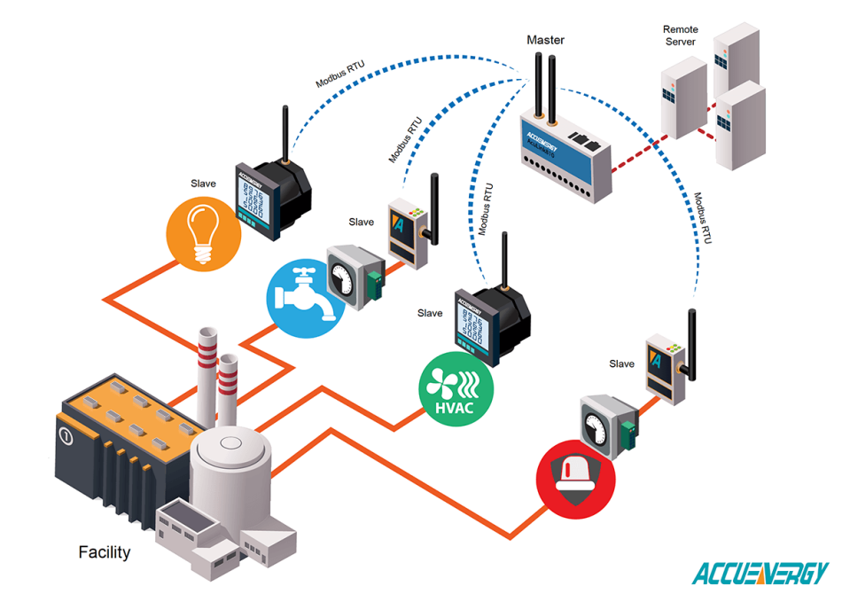
Modbus is a communication protocol based on a master-slave structure. It uses RS-485, RS-422, RS-232 interfaces, and Ethernet TCP/IP network (Modbus TCP protocol) for data transmission.
Modbus RTU messages include:
- Address of SlaveID device
- function code
- Special data dependent on function codes
- CRC-16(Modbus)
The structure is as follows:
SlaveID 功能码 特殊数据 CRC16
If you remove the SlaveID address and CRC-16 (Modbus), you will get a PDU (Protocol Data Unit).
SlaveID is the address of the device, which can be selected as a value between 0 and 247. It is worth noting that addresses from 248 to 255 are reserved.
The data in the module is stored in four tables, two of which are read-only and the other two are read-write. Each table can hold 9999 values.
The following is a summary of the table:
- Discrete output coil (DO)Read and write; Register number 1-9999; HEX address range 0000 to 270E
- Discrete Input Contact (DI)Read only; Register number 10001-19999; HEX address range 0000 to 270E
- Analog Input Register (AI)Read only; Register number 30001-39999; HEX address range 0000 to 270E
- Analog output hold register (AO)Read and write; Register number 40001-49999; HEX address range 0000 to 270E
Each table has a register number (such as AO's 40001), which corresponds to an address (such as 0000). This difference is called 'offset'. The offsets of the table are 1, 10001, 30001, and 40001, respectively.
Using an example, the Modbus RTU request for obtaining AI values from registers 40108 to 40110 at device address 17 is as follows:
11 03 006B 0003 7687
This decomposition is as follows:
11SlaveID device address (17 in decimal or 11 in HEX)03: Function code006BThe address of the first register (calculated as 40108-40001=107, which is 6B in HEX)0003Required number of registers (obtain three registers from 40108 to 40110)7687CRC checksum
Modbus RTU slave device will reply:
11 03 06 AE41 5652 4340 49AD
This translates into:
- Device address:
11(or 17 in decimal) - Function Code:
03 - Byte count (indicating followed by 6 bytes):
06 - Register values AO0, AO1, and AO2 as a two byte sequence
- The CRC value is determined by
49ADprovide
The values of analog output registers can be interpreted in various ways, such as:
- As a 16 bit unsigned integer (range 0 to 65535)
- As a 16 bit signed integer (range -32768 to 32767)
- As a two character ASCII string
- As a discrete on/off value (0 or 1)
- As a 32-bit unsigned integer (range 0 to 4294967295)
- As a 32-bit signed integer (range -2147483648 to 2147483647)
- As a 32-bit single precision IEEE floating-point number (ranging from 1.2 × 10 ^ -38 to 3.4 × 10 ^+38)
- As a four character ASCII string

What is the Modbus RTU command?
The following is a code table for reading and writing Modbus RTU registers.
| Function code | Functional Operations | data type | Access type |
|---|---|---|---|
| 01 (0x01) | Read DO | Discrete output coil state | read |
| 02 (0x02) | Read DI | Discrete input state | read |
| 03 (0x03) | Read AO | holding register | 16 bits |
| 04 (0x04) | Read AI | input register | 16 bits |
| 05 (0x05) | Write a DO | Compulsory single coil | discrete |
| 06 (0x06) | Write an AO | Preset single register | 16 bits |
| 15 (0x0F) | Multiple DO writes | Mandatory multi coil | discrete |
| 16 (0x10) | Multiple AO writes | Preset multiple registers | 16 bits |
How to send Modbus RTU commands to read discrete outputs? Command 0x01
This command is used to read the value of DO digital output.
The PDU request specifies the starting address of the first DO register and the number of DO values required thereafter. In PDU, DO values are addressed starting from zero.
The DO value in the response is one byte, corresponding to the value of the corresponding bit.
The bit value is defined as 1=ON and 0=OFF.
The lower bits of the first data byte contain the DO value of the specified address in the request. The remaining DO values are increased to the highest value of the byte. From right to left.
If the requested DO value is less than eight, the remaining bits in the response will be filled with zeros (in the direction from low byte to high byte). Byte count further represents the complete number of bytes of data in the response.
An example of a DO query from 20 to 56, targeting the SlaveID address 17 of the device. The address of the first register will be 0013 hexadecimal=19, because the account starts from a 0 address (0014 hexadecimal=20, -1 zero offset=we get 0013 hexadecimal=19).
| byte | Request | byte | Reply |
|---|---|---|---|
| (Hex) | field name | (Hex) | field name |
| 11 | Device address | 11 | Device address |
| 01 | Function code | 01 | Function code |
| 00 | The high byte of the first register address | 05 | More bytes |
| 13 | The low byte of the first register address | CD | Register value of DO 27-20 (1100 1101) |
| 00 | High number of registers in bytes | 6B | Register value of DO 35-28 (0110 1011) |
| 25 | Low number of registers in bytes | B2 | Register value of DO 43-36 (1011 0010) |
| 0E | CRC-16(Modbus) | 0E | Register value of DO 51-44 (0000 1110) |
| 84 | CRC-16(Modbus) | 1B | Register value of DO 56-52 (0001 1011) |
| 45 | CRC-16(Modbus) | ||
| E6 | CRC-16(Modbus) | ||
| The output status of DO 27-20 is displayed as byte CD hexadecimal value, or 1100 1101 in binary system. |
In register DO 56-52, 5 bits are requested on the right side, and the remaining bits are filled with zeros to obtain the complete byte (0001 1011).
| passage | - | - | - | DO 56 | DO 55 | DO 54 | DO 53 | DO 52 |
|---|---|---|---|---|---|---|---|---|
| bit | 0 | 0 | 0 | 1 | 1 | 0 | 1 | 1 |
| hexadecimal | 1B |
How to send Modbus RTU commands to read digital inputs? Command 0x02
This command is used to read the value of the digital input DI.
Example of DI request from register # 10197 to 10218, targeting device SlaveID address 17. The address of the first register will be 00C4 hexadecimal=196, as the account starts from address 0.
| byte | Request | byte | Reply |
|---|---|---|---|
| (Hex) | field name | (Hex) | field name |
| 11 | Device address | 11 | Device address |
| 02 | Function code | 02 | Function code |
| 00 | The high byte of the first register address | 03 | More bytes |
| C4 | The low byte of the first register address | AC | Register value of DI 10204-10197 (1010 1100) |
| 00 | High number of registers in bytes | DB | Register value of DI 10212-10205 (1101 1011) |
| 16 | Low number of registers in bytes | 35 | Register values of DI 10218-10213 (0011 0101) |
| BA | CRC-16(Modbus) | 20 | CRC-16(Modbus) |
| A9 | CRC-16(Modbus) | 18 | CRC-16(Modbus) |
How to send Modbus RTU commands to read analog outputs? Command 0x03
This command is used to read the value of the analog output AO.
Example of AO request from register # 40108 to 40110, targeting device SlaveID address 17. The address of the first register will be 006B hexadecimal=107, as the account starts from address 0.
| byte | Request | byte | Reply |
|---|---|---|---|
| (Hex) | field name | ( |
Hex) | Field Name
11 | Device Address | 11 | Device Address
03 | Function Code | 03 | Function Code
00 | First register address high byte | 06 | More bytes
6B | Low byte of first register address | AE | High bit of register value # 40108
00 | Number of registers high byte | 41 | Low register value of # 40108
03 | Number of registers low byte | 56 | Register value high bit of # 40109
76 | CRC checksum | 52 | Low register value of # 40109
87 | CRC checksum | 43 | High register value of # 40110
Register value low of 40 | # 40110
49 | CRC-16(Modbus)
AD | CRC-16(Modbus)
How to send Modbus RTU commands to read analog inputs? Command 0x04
This command is used to read the value of the simulated input AI.
Example AI request from register # 30009, targeting device SlaveID address 17. The address of the first register is 0008 hexadecimal=8, because the account starts from address 0.
| byte | Request | byte | Reply |
|---|---|---|---|
| (Hex) | field name | (Hex) | field name |
| 11 | Device address | 11 | Device address |
| 04 | Function code | 04 | Function code |
| 00 | The high byte of the first register address | 02 | More bytes |
| 08 | The low byte of the first register address | 00 | #Register value high of 30009 |
| 00 | High number of registers in bytes | 0A | #Low register value of 30009 |
| 01 | Low number of registers in bytes | F8 | CRC-16(Modbus) |
| B2 | CRC-16(Modbus) | F4 | CRC-16(Modbus) |
| 98 | CRC-16(Modbus) |
How to send Modbus RTU commands to write discrete outputs? Command 0x05
This command is used to record a value of DO digital output.
The value FF 00 hexadecimal sets the output to ON.
Set the output to OFF in hexadecimal with a value of 00 00.
All other values are invalid and will not affect the output value.
The normal response to such requests is echo (duplicate requests in the response), which is returned after the DO status has changed.
For example, use the DO record of register # 173 with SlaveID address 17 of the device. The register address is 00AC hexadecimal=172 because recording starts from address 0.
| byte | Request | byte | Reply |
|---|---|---|---|
| (Hex) | field name | (Hex) | field name |
| 11 | Device address | 11 | Device address |
| 05 | Function code | 05 | Function code |
| 00 | The high byte of the first register address | 00 | The high byte of the first register address |
| AC | The low byte of the first register address | AC | The low byte of the first register address |
| FF | High byte value | FF | High byte value |
| 00 | Low byte value | 00 | Low byte value |
| 4E | CRC-16(Modbus) | 4E | CRC-16(Modbus) |
| 8B | CRC-16(Modbus) | 8B | CRC-16(Modbus) |
| The output status of DO173 has been changed from OFF to ON. |
How to send Modbus RTU commands to record analog outputs? Command 0x06
This command is used to record a value of the simulated output AO.
For example, use the AO record of register # 40002 with SlaveID address 17 of the device. The address of the first register is 0001 hexadecimal=1, as recording starts from address 0.
| byte | Request | byte | Reply |
|---|---|---|---|
| (Hex) | field name | (Hex) | field name |
| 11 | Device address | 11 | Device address |
| 06 | Function code | 06 | Function code |
| 00 | The high byte of the first register address | 00 | The high byte of the first register address |
| 01 | The low byte of the first register address | 01 | The low byte of the first register address |
| 00 | High byte value | 00 | High byte value |
| 03 | Low byte value | 03 | Low byte value |
| 9A | CRC-16(Modbus) | 9A | CRC-16(Modbus) |
| 9B | CRC-16(Modbus) | 9B | CRC-16(Modbus) |
How to send Modbus RTU commands to write to multiple discrete pins? Command 0x0F
This command is used to record multiple values of DO digital output.
For example, write multiple DOs from registers # 20 to # 29 of device SlaveID address 17. The register address is 0013 hexadecimal=19, as recording starts from address 0.
| byte | Request | byte | Reply |
|---|---|---|---|
| (Hex) | field name | (Hex) | field name |
| 11 | Device address | 11 | Device address |
| 0F | Function code | 0F | Function code |
| 00 | The high byte of the first register address | 00 | The high byte of the first register address |
| 13 | The low byte of the first register address | 13 | The low byte of the first register address |
| 00 | High number of registers in bytes | 00 | High number of recorded registers in bytes |
| 0A | Low number of registers in bytes | 0A | The number of recorded registers is low in bytes |
| 02 | More bytes | 26 | CRC-16(Modbus) |
| CD | Byte value of DO 27-20 (1100 1101) | 99 | CRC-16(Modbus) |
| 01 | Byte value of DO 29-28 (0000 0001) | ||
| BF | CRC-16(Modbus) | ||
| 0B | CRC-16(Modbus) |
The answer returns the number of recorded registers.
How to send Modbus RTU commands to record multiple analog outputs? Command 0x10
This command is used to record multiple values of simulated output AO.
For example, record multiple AOs from registers # 40002 and # 40003 at SlaveID address 17 of the device. The address of the first register is 0001 hexadecimal=1, as recording starts from address 0.
| byte | Request | byte | Reply |
|---|---|---|---|
| (Hex) | field name | (Hex) | field name |
| 11 | Device address | 11 | Device address |
| 10 | Function code | 10 | Function code |
| 00 | The high byte of the first register address | 00 | The high byte of the first register address |
| 01 | The low byte of the first register address | 01 | The low byte of the first register address |
| 00 | High number of registers in bytes | 00 | High number of recorded registers in bytes |
| 02 | Low number of registers in bytes | 02 | The number of recorded registers is low in bytes |
| 04 | More bytes | 12 | CRC-16(Modbus) |
| 00 | 40002 high value | 98 | CRC-16(Modbus) |
| 0A | 40002 low value | ||
| 01 | 40003 high value | ||
| 02 | 40003 low value | ||
| C6 | CRC-16(Modbus) | ||
| F0 | CRC-16(Modbus) |
Error in Modbus request
If a device receives a request but is unable to process it, the device will respond with an error code.
The response will include the modified functional code, with the high-order byte being 1.
Example:
| raw value | result value |
|---|---|
| Function code in the request | Functional error codes in response |
| 01 (01 hex) 0000 0001 | 129 (81 hex) 1000 0001 |
| 02 (02 hex) 0000 0010 | 130 (82 hex) 1000 0010 |
| 03 (03 hex) 0000 0011 | 131 (83 hex) 1000 0011 |
| 04 (04 hex) 0000 0100 | 132 (84 hex) 1000 0100 |
| 05 (05 hex) 0000 0101 | 133 (85 hex) 1000 0101 |
| 06 (06 hex) 0000 0110 | 134 (86 hex) 1000 0110 |
| 15 (0F hex) 0000 1111 | 143 (8F hex) 1000 1111 |
| 16 (10 hex) 0001 0000 | 144 (90 hex) 1001 0000 |
Example of requests and responses with errors:
| byte | Request | byte | Response |
|---|---|---|---|
| (Hex) | field name | (Hex) | field name |
| 0A | Device address | 0A | Device address |
| 01 | Function code | 81 | Modified functional code |
| 04 | The high byte of the first register address | 02 | error code |
| A1 | The low byte of the first register address | B0 | CRC-16(Modbus) |
| 00 | High number of registers in bytes | 53 | CRC-16(Modbus) |
| 01 | Low number of registers in bytes | ||
| AC | CRC-16(Modbus) | ||
| 63 | CRC-16(Modbus) |
Error code description
01 | Cannot process accepted functional code.
02 | The data address specified in the request is not available.
03 | The value contained in the query data field is invalid.
04 | An unrecoverable error occurred while attempting to execute the requested operation from the slave station.
05 | The slave station has accepted the request and is processing it, but it will take a long time. This response prevents the host from generating timeout errors.
06 | The slave is busy processing commands. The host must repeat messages when the slave is idle.
07 | The slave cannot execute the program function specified in the request. This code is returned for unsuccessful program requests using function numbers 13 or 14. The host must request diagnostic or error information from the slave.
08 | Parity error detected while reading extended memory from the station. The host can make repeated requests, but usually requires maintenance in such situations.


Leave a Reply