
Application of Modbus Protocol. This section mainly explains the following parts:
- Enabling the Protocol,
- Configuring the Master and Slave,
- Creating Variables,
- Relationship between Variable Address and Value,
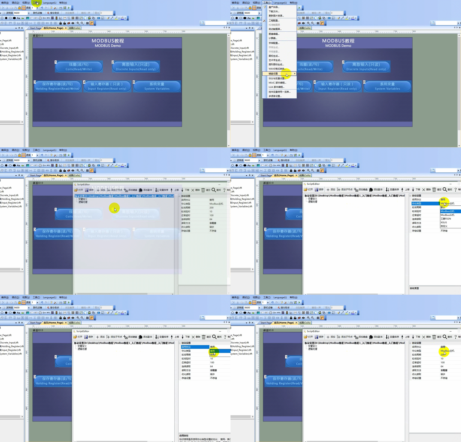
1.1 Enabling the Protocol. The Modbus protocol configuration interface is located in the menu bar of the VisualTFT host computer, under "Tools" → "Protocol and Variable Settings…". Click on the file path on the left, and in the protocol settings column on the right, set the protocol type. If you select Modbus Master, enable the protocol as shown below
The configuration interface for the Modbus protocol can be found on the menu bar of the VisualTFT host computer under "Tools" → "Protocol and Variable Settings…". Click on the file path on the left, and in the protocol settings section on the right, set the protocol type. If you choose Modbus master, enable the protocol as shown below
. After enabling the Modbus protocol, the control can display "Associated Variables" on the configuration interface.
1.2 Configuring the Master and Slave.
Master Mode.
Configuration of the Modbus Master, with parameters shown below
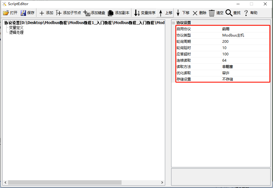
- . Enabling the Protocol: The Modbus protocol is only supported when the protocol is enabled
- Protocol Type: Select Modbus Master
- Polling Cycle: Invalid parameter, do not set
- Polling Delay: When the screen acts as the master, the time to wait for sending the next request command after sending a request command and receiving a response from the screen
- Response Timeout: When the screen acts as the master, the maximum delay allowed for slaves, default is 100 milliseconds
- Continuous Reading: Set the maximum number of continuous address variables to read
- Optimized Reading: After enabling optimized reading, only variables related to the current screen are read
- Storage Settings: After enabling storage, Flash addresses 0~2048, approximately 2K, are used to store all Modbus variables. Other storage should avoid this address!!! Do Not Store: Do not store, variables will return to default values after power-off and restart. Store All: Not recommended, as frequent storage can lead to an increase in bad blocks in FLASH. Store Specified Variables: Recommended for use, generally used to store system configuration parameters that rarely change
- Storage Marker: Identify the data version marker stored in the screen. When the storage data format changes, it is generally necessary to manually modify this storage marker value
Slave Mode
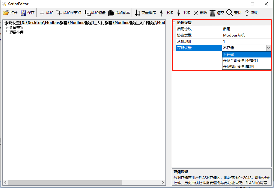
- Enable Protocol: The protocol needs to be enabled to support the Modbus protocol
- Protocol Type: Select Modbus Slave
- Slave Address: Default is 1
- Storage Settings: After enabling storage, Flash addresses 0~2048, approximately 2K, are reserved for Modbus variable storage. Other storage should avoid these addresses! Do Not Store: Do not store. After power-off and restart, variables will return to their default values. Store All: Not recommended, as frequent storage can lead to an increase in FLASH bad blocks. Store Specified Variables: Recommended for use, generally used to store system configuration parameters that rarely change.
- Storage Mark: Identify the data version mark stored on the screen. When the storage data format changes, the storage mark value generally needs to be manually modified.
1.3 Create Variable
Click "Variable Definition", then click "Add" to add a variable, as shown below.
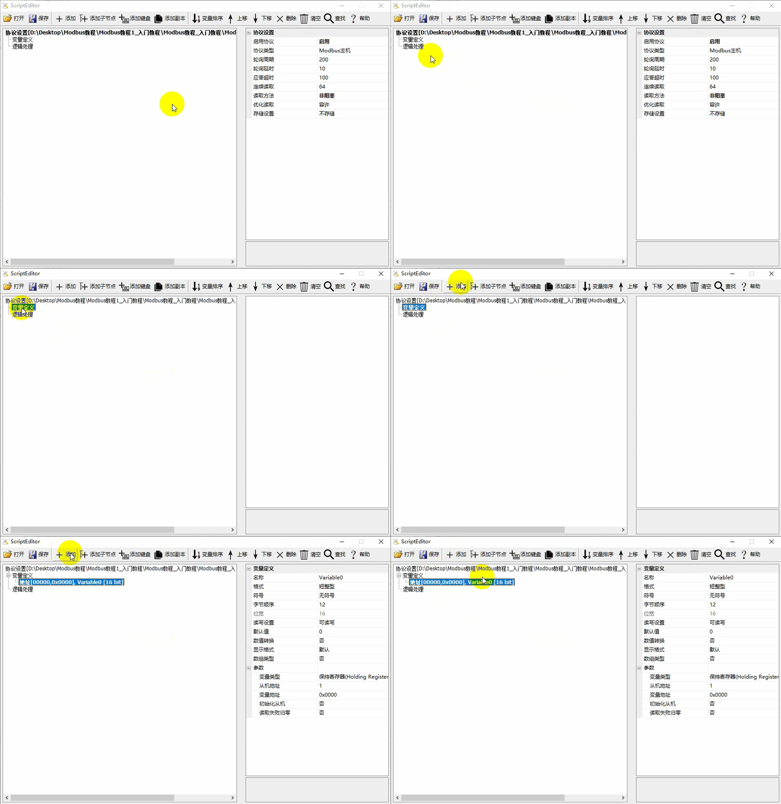
Variable Definition
Detailed variable analysis is as follows:
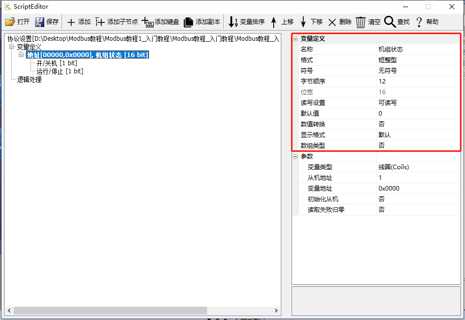
- Name: The default variable names are "Variable1, Variable2, Variable3...", which can be defined with meaningful names such as: unit status; if the variable needs to be bit-wise interpreted, the default names are "Field1, Field2, Field3...", which can be defined with meaningful names such as: on/off, run/stop.
- Format: Supports short integer, long integer, single-precision floating-point number, and string.
- Sign: Can be set to unsigned or signed.
- Read-Write Settings: Set the read-write permissions for the variable, supporting read-write, read-only, and write-only.
- Default Value: The default display value.
- Numerical Conversion: Convert the variable, for example: actual value = original value * scaling + translation
- Display format: Set the number of digits for integers and decimals
- Array type: Enable array type, starting from the address of this variable, operate on consecutive N registers
- Storage: Enable storage settings when configuring Modbus master/slave protocol. If storage is selected here, data can be saved during power loss
Parameters
Detailed parameter setting analysis is shown below
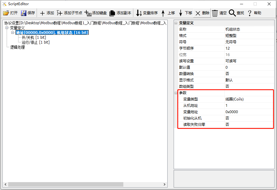
- Variable type: Coil, discrete input, hold register, input register, memory variable, system variable
- Slave address: Only required when the screen acts as a master
- Variable address: The address of the variable (or register), entered in hexadecimal
- Initialize slave: When the screen acts as a master, after power-on, write the value of the variable to the slave device
- Reset to zero on read failure: When the screen acts as a master, if the variable fails to be read, the value of the variable is reset to zero
1.4 Relationship between variable address and value
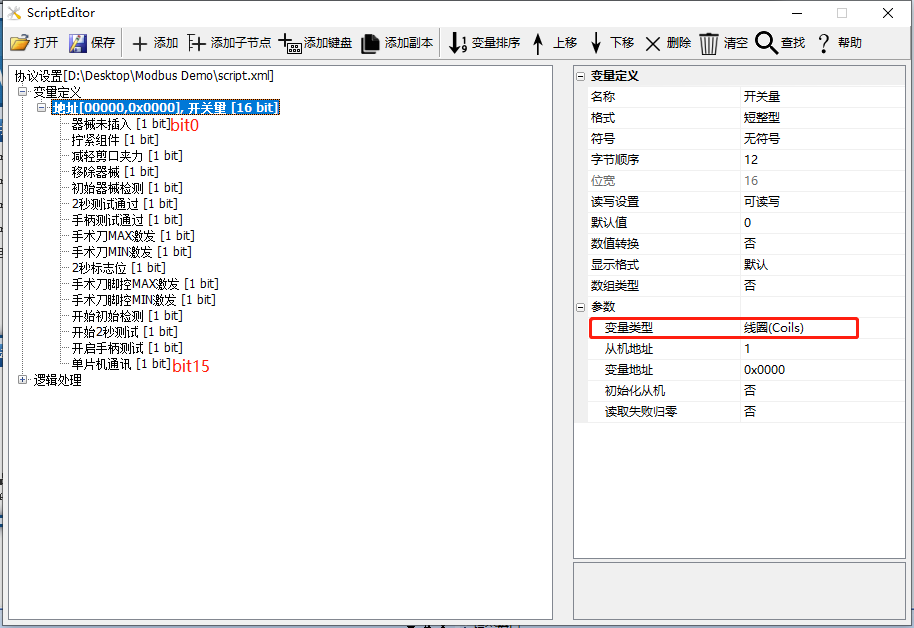
Coil/discrete data
Create a coil or discrete input register with a variable format of short integer type, which contains 16 coils (from top to bottom, bit0...bit15). Assuming the variable address is 0x0000, the variable includes addresses ranging from 0x0000 to 0x000F. Each bit corresponds to one coil, as shown below.
String type
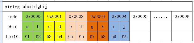
Create a save register with a variable format of string type (default 32 characters). Assuming the variable address is 0x0000, this string corresponds to variables within the address range of 0x0000 to 0x000F, with one address corresponding to two characters.
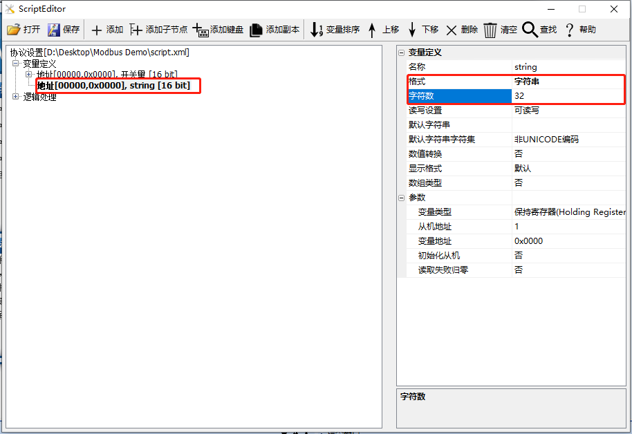
Assuming the save register at address 0x0000 has a value of 'abcdefghij', as shown below.
Array
Create an input register of array type (default array size is 10, with subscripts starting from 0). Assuming the variable address is 0x0000, this variable represents 10 consecutive variables starting from 0x0000, with each array subscript corresponding to one variable.
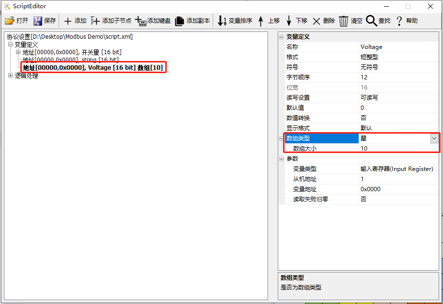
Assuming a variable is created as an input register of type Voltage, with an array type and size of 10, the correspondence is as follows



Leave a Reply