
I. Product Overview
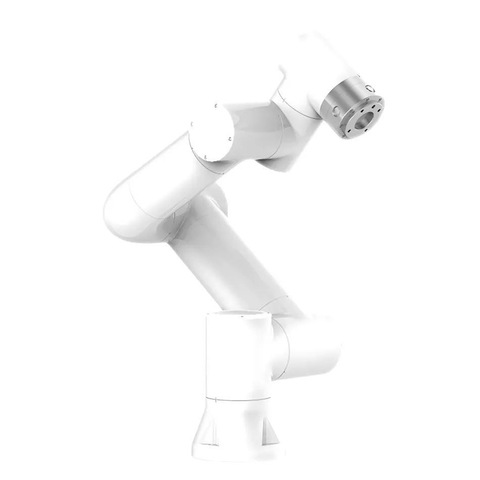
Collaborative robots are high-performance industrial robots that integrate real-time control systems. It combines features such as flexibility, safety, ease of use, and agility, while also possessing industrial grade precision and stability. This robot is designed to meet the needs of modern industrial automation and can be widely used in multiple industries, providing efficient and reliable automation solutions.
2, Functional Features
(1) Real time control system
The collaborative robot adopts an advanced real-time control system to ensure the accuracy and stability of motion. The system is capable of quickly responding to external commands, achieving precise positioning and motion control.
(II) Flexibility and Safety
Robots have excellent flexibility and can adapt to different working environments and task requirements. Its safety design complies with international standards, including emergency stop, collision detection and other functions, ensuring the safety of operators and equipment.
(III) Usability and Flexibility
The collaborative robot adopts a graphical programming interface, zero force teaching, and sliding drag function, making operation and programming simple and intuitive. The multi axis linkage design further enhances the flexibility of the robot and enables it to easily handle complex tasks.
(IV) Industrial grade accuracy and stability
The robot has a repeatability accuracy of ± 0.02mm and meets the ISO 9283 standard. Modular design ensures the stability and maintainability of the system.
III. Main Features
(1) Safe, Stable, and Reliable
The collaborative robot has high-precision repeat positioning capability, with a repeat positioning accuracy of ± 0.02mm. The modular design ensures the stability and scalability of the system.
(II) Flexible Deployment
The robot adopts graphical programming, zero force teaching, and silky drag and drop functions, making deployment simple and fast. The multi axis linkage design further enhances the adaptability of the robot.
(III) Efficient Protection
Robots have efficient protection mechanisms and can adapt to various complex working environments. The protection level reaches IP54 (optional IP66), ensuring the normal operation of the equipment in harsh environments.
(IV) Ecological improvement
Support ROS secondary development to meet more diverse needs. Supporting multiple communication protocol methods, providing convenience for device manufacturers and integrators.
(5) Widely used
Collaborative robots are suitable for various industries such as assembly, picking and placing, twisting screws, dispensing, monitoring, catering, moxibustion, and medical care. The on-site teaching service nationwide ensures the smooth implementation of the project.
4, Application Fields
Collaborative robots are widely used in households, office buildings, hotels, banks, hospitals, schools, airports, museums, laboratories, factories, agriculture, and other users who require electric robotic arms. Meanwhile, it is also suitable for professionals in equipment manufacturing, robot manufacturing, security manufacturing, and other fields.
5, Basic parameters of robotic arm
(1) Product parameters
- Product TypeElectric motor arm
- Model: UD01
- Payload: 5kg
- working radius: 922mm
- degrees of freedom: 6 rotating joints
- human-computer interaction10.1-inch teaching pendant or web server
- Protection RatingIP54 (IP66 optional)
- noise: < 65db
- Installation direction: In any direction
- I/O port: Digital Input (DI) 2; Digital output (DO) 2; Analog Input (AI) 2; Analog output (AO) 2; High speed pulse input 2
- tool I/O power supply: 24V/1.5A
- Base diameter: 149mm
- Total weight: ≈ 22kg (excluding wire)
- Operating Temperature: 0-45℃
- Operating Humidity: 90%RH (non-condensing)
- Equipment and materialsAluminum, steel
6, Motion characteristics of robotic arm
(1) Accuracy
- Repetitive positioning accuracy: ± 0.02mm
- pose repeatability in accordance with ISO 9283: ± 0.03mm
(II) Moving axis
| Moving axis | Working range | Maximum speed |
|---|---|---|
| Base | ± 175 ° | ± 180 °/s |
| Shoulder | + 85°/- 265° | ±180°/s |
| elbow | ±160° | ±180°/s |
| Wrist 1 | + 85°/- 265° | ±180°/s |
| Wrist 2 | ±175° | ±180°/s |
| Wrist 3 | ±175° | ±180°/s |
| Typical TCP speed | 1m/s | - |
7, Mini control box 2kw
(1) Equipment parameters
- Equipment weight: 2.5kg (excluding wire)
- Equipment and materialsGalvanized sheet
- dimensional parameters: 24518044.5mm (excluding protrusions)
- Protection Rating: IP54
- Operating Temperature: 0-45℃
- Operating Humidity: 90%RH (non-condensing)
- I/O portDigital Input (DI) 16; Digital output (DO) 16; Analog Input (AI) 2; Analog output (AO) 2; High speed pulse input 2
- I/O power supply: 24V/1.5A
- communication: I/O, TCP/IP, Modbus TCP/RTU
- Development Environment: C #/C++/Python/Java/ROS
8. Button Box
(1) Equipment Parameters
- Equipment Weight: 490g (with wire weight)
- Equipment Material: ABS
- Size Parameters: 1306066mm (excluding protrusions)
- Protection level: IP54
- Cable length: 5m
- Button count: ≥ 200000 times
- Protocol type: TCP/IP
- Network transmission rate: 100M
- Button function: manual/automatic, drag, point recording, whether to cooperate with button box, start/stop, shutdown
- Power Supply: Standard POE
9. Teaching pendant (optional)
(1) Equipment Parameters
- Equipment Weight: 1.6kg (wire weight)
- Equipment Material: ABS, PP
- Size Parameters: 26821088mm
- Protection Level: IP54
- Operating humidity: 90% RH (non condensing)
- Cable length: 5m
- Display resolution: 1280 * 800 pixels
X. Communication parameters
Communication parameters are 9600 8 N 1, ensuring the stability and reliability of data transmission.
XI. Function Register Address
(I) Read Coils (0x)
| Function Code | Register name | Read/write | Register address in decimal | Register address in hexadecimal | Value | Value meaning | Remarks |
|---|---|---|---|---|---|---|---|
| 01 | DI1 | Read/write | 0100 | 0064 | 00 00 | 1: Start motion 0: Stop motion | Background preset motion track |
| DI2 | Read/Write | 0101 | 0065 | 00 00 | 1: Start Motion 0: Stop Motion | Background Preset Motion Trajectory | |
| DI3 | Read/Write | 0102 | 0066 | 00 00 | 1: Start Motion 0: Stop Motion | Background Preset Motion Trajectory | |
| DI4 | Read/Write | 0103 | 0067 | 00 00 | 1: Start Motion 0: Stop Motion | Background Preset Motion Trajectory | |
| DI5 | Read/Write | 0104 | 0068 | 00 | 1: Start Motion 0: Stop Motion | Background Preset Motion Trajectory | |
| DI6 | Read/Write | 0105 | 0069 | 00 | 1: Start Motion 0: Stop Motion | Background Preset Motion Trajectory | |
| DI7 | Read/Write | 0106 | 006A | 00 00 | 1: Start Motion 0: Stop Motion | Background Preset Motion Trajectory | |
| DI8 | Read/Write | 0107 | 006B | 00 00 | 1: Start Motion 0: Stop Motion | Background Preset Motion Trajectory | |
| DI9 | Read/Write | 0108 | 006C | 00 00 | 1: Start Motion 0: Stop Motion | Background Preset Motion Trajectory | |
| DI10 | Read/Write | 0109 | 006D | 00 | 1: Start Motion 0: Stop Motion | Background Preset Motion Trajectory | |
| Pause | Write | 0500 | 01 F4 | 00 00 | Jogging signal, first send 1, then need to send 0 within one second to put him in that state | - | |
| Start | Write | 0501 | 01 F5 | 00 00 | Jogging signal, first send 1, then need to send 0 within one second to put him in that state | - | |
| Restore | Write | 0502 | 01 F6 | 00 00 | Jogging signal, first send 1, then need to send 0 within one second to put him in that state | - | |
| Stop | Write | 0503 | 01 F7 | 00 00 | Jogging signal, first send 1, then need to send 0 within one second to put him in that state | - | |
| Move to origin | Write | 0504 | 01 F8 | 00 00 | Jogging signal, first send 1, then need to send 0 within one second to put him in that state | - | |
| Manual automatic mode switching | Write | 0505 | 01 F9 | 00 00 | Jogging signal, first send 1, then need to send 0 within one second to put him in that state | - | |
| Start the main program | Write | 0506 | 01 FA | 00 00 | jog signal, send 1 first, and then send 0 again within one second to put it in this state | - |
(II) Read Discrete Input (1X)
| Function code | Register name | Read/write | Register address in decimal | Register address in hexadecimal | Value | Value meaning | Remarks |
|---|---|---|---|---|---|---|---|
| 02 | Start exercising | Read | 0100 | 0064 | 00 00 | - | - |
| Complete the action | Read | 0101 | 0065 | 00 00 | - | - | |
| DO2 | Read | 0102 | 0066 | 00 00 | - | - | |
| DO3 | Read | 0103 | 0067 | 00 00 | - | - | |
| DO4 | Read | 0104 | 0068 | 00 00 | - | - | |
| DO5 | Read | 0105 | 0069 | 00 00 | - | - | |
| DO6 | Read | 0106 | 006A | 00 00 | - | - | |
| DO7 | Read | 0107 | 006B | 00 00 | - | - | |
| DO8 | Read | 0108 | 006C | 00 00 | - | - | |
| DO9 | Read | 0109 | 006D | 00 00 | - | - |
(3) Read Input Register (3X)
| function code | Register name | Read/Write | Register address in decimal format | Register address in hexadecimal format | Value | Value meaning | Remark |
|---|---|---|---|---|---|---|---|
| 04 | Enabled state | Read | 0310 | 01 36 | 00 00 | 1: In enabled state 0: Not in enabled state | - |
| Mode | Read | 0311 | 01 37 | 00 00 | 1: Manual 0: Automatic | - | |
| Status | Read | 0312 | 01 38 | 00 00 | 1: Stop 2: Run 3: Pause 4: Drag | - | |
| Workpiece Number NR | Read | 0313 | 01 39 | 00 | - | - | |
| Workpiece Number NR | Read | 0314 | 01 3A | 00 00 | - | - | |
| Emergency stop status | Read | 0315 | 01 3B | 00 00 | 0: Running 1: Emergency stop | Is it in emergency stop | |
| Main fault code | Read | 0316 | 01 3C | 00 | - | - | |
| Sub fault code | Read | 0317 | 01 3D | 00 00 | - | - | |
| Collision state | Read | 0318 | 01 3E | 00 00 | 1: Collision 0: No collision | - | |
| Move to position | Read | 0319 | 01 3F | 00 00 | 1: Movement to position 0: No movement to position | - | |
| Safety stop signal S10 | Read | 0320 | 01 40 | 00 00 | 1: The robotic arm is in a stopped state 0: not in a stopped state | - | |
| Safety stop signal S11 | Read | 0321 | 01 41 | 00 00 | - | - |
12, Installation and Debugging
(1) Installation environment
Collaborative robots should be installed in a stable, dry, and non corrosive gas environment. During installation, it is necessary to ensure sufficient space around for easy operation and maintenance.
(II) Electrical Connection
The robot needs to be connected to a stable power source to ensure that the voltage and frequency meet the equipment requirements. All electrical connections should be made by professionals to avoid equipment damage or safety accidents caused by improper connections.
(III) Debugging steps
- Power on check: After connecting the power, check whether the various components of the robot are running normally, including joint motion, control system response, etc.
- Parameter Setting: Set the working parameters of the robot according to actual application requirements, such as load, speed, accuracy, etc.
- Teaching Programming: Use a teaching device or programming software to teach programming of robots, set work trajectories and action sequences.
- Safety TestBefore formal operation, conduct safety testing to ensure that the robot's emergency stop, collision detection, and other functions are working properly.
13, Maintenance and upkeep
(1) Daily maintenance
- cleanRegularly clean the surface of the robot to avoid the accumulation of dust and dirt that may affect equipment performance.
- Check the connectionCheck whether the connections of each component are firm and ensure the safety of electrical and mechanical connections.
- Lubrication: Regularly lubricate robot joints and moving parts to reduce wear and extend equipment lifespan.
(II) Regular Maintenance
- Performance Testing: Regularly conduct performance testing to check whether the accuracy, speed, and stability of the robot meet the requirements.
- Component Replacement: Replace worn components such as seals, bearings, etc. in a timely manner based on equipment usage.
- System UpdateRegularly update the software of the control system to ensure that the equipment has the latest features and performance optimization.
14, Frequently Asked Questions and Answers
(1) The robot cannot start
- Possible reasons: Improper power connection, control system malfunction, emergency stop button triggered.
- SolutionCheck if the power connection is correct, restart the control system, and verify if the emergency stop button has been triggered and reset.
(2) Robot motion accuracy decreases
- Possible reasonsJoint wear, insufficient lubrication, and control system parameter drift.
- SolutionCheck joint wear and perform maintenance, replenish lubricant, and recalibrate control system parameters.
(3) Robot malfunction alarm
- Possible reasonsOverload, collision, electrical malfunction.
- SolutionCheck if the load exceeds the rated load of the robot, review collision detection records and eliminate collision factors, and check the electrical connections and control system status.
15, Appendix
(1) Technical specification sheet
| Product Model | UD01 |
|---|---|
| Payload | 5kg |
| working radius | 922mm |
| degrees of freedom | 6 rotating joints |
| Repetitive positioning accuracy | ±0.02mm |
| Operating Temperature | 0-45℃ |
| Operating Humidity | 90%RH (non-condensing) |
| Protection Rating | IP54 (IP66 optional) |
| Total weight | ≈ 22kg (excluding wires) |
(2) Communication Protocol Specification
| communication parameters | 9600 8 N 1 |
|---|---|
| Protocol Type | TCP/IP, Modbus_TCP/RTU |
(3) Fault code table
| fault code | Fault description | Solution |
|---|---|---|
| 01 | Overload | Reduce load and inspect mechanical components |
| 02 | collision | Check the cause of the collision and reset the system |
| 03 | Electrical malfunction | Check the electrical connections and restart the control system |
| 04 | Programming Error | Check program logic and re upload program |


Leave a Reply