Description
Product Introduction
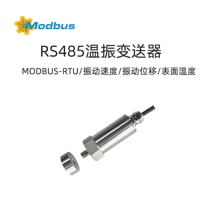
Modbus Temperature Vibration Transmitter is a high-performance, low-power, anti-interference, and composite vibration sensor developed and produced using embedded technology, temperature sensing technology, and vibration sensing technology using MEMS chips. The product is widely used in the online measurement of temperature and vibration of rotating equipment such as motors, reducers, fans, generators, air compressors, centrifuges, and water pumps in industries such as coal mining, chemical engineering, metallurgy, and power generation.
Product Selection
| RS- |
|
Company Code |
|
WZ3- |
|
Temperature+vibration (three-axis) collector |
| WZ1- |
|
Temperature+Vibration (Uniaxial) Collector |
| WZ3A- |
|
Temperature+vibration (three-axis) collector |
| WZ1A- |
|
Temperature+Vibration (Uniaxial) Collector |
|
N01- |
|
RS485 (Modbus RTU protocol) |
|
1- |
|
First generation appearance |
|
M10 |
M10 external thread |
| M8 |
M8 external thread |
| M5 |
M5 external thread |
| CX |
magnetic installation |
Features
- The product adopts high-performance MEMS chips, with high measurement accuracy and strong anti-interference ability.
- The product provides methods such as threaded installation and magnetic suction installation.
- It can measure parameters such as single axis and three-axis vibration velocity, vibration displacement, etc.
- Can measure the surface temperature of the motor.
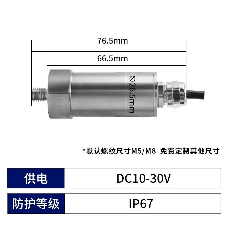
- 10-30V DC wide voltage power supply.
- Protection level IP67.
- Support remote upgrade.
Technical Parameters
| power supply |
DC10-30V |
| power consumption |
0.3W(DC24V) |
| Protection Rating |
IP67 |
| Frequency range (Hz) |
10-1600 or 10-5000 |
| Vibration measurement direction |
Single axis or three-axis |
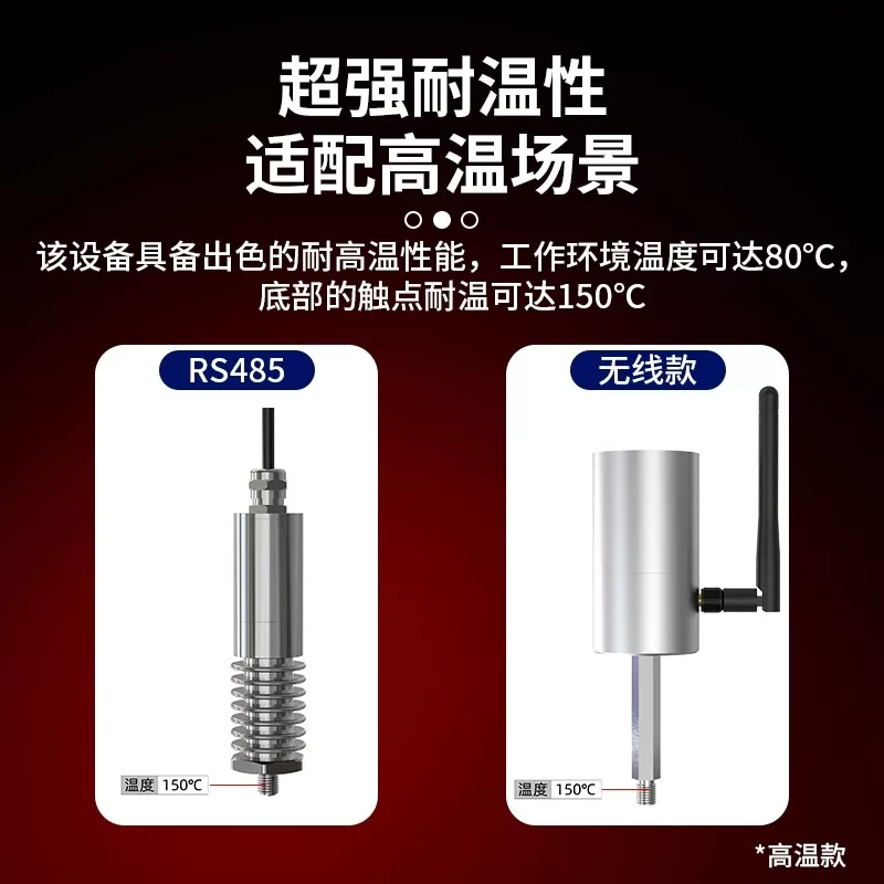
| Operating temperature of transmitter circuit |
-40℃~+80℃ , 0%RH~80%RH |
| Temperature range that transmitter contacts can withstand |
-40-150 ℃ (default 85 ℃) |
| Vibration velocity measurement range (mm/s) |
0-50 |
| Measurement accuracy of vibration velocity |
<1% (@160Hz , 10mm/s) |
| Vibration speed display resolution (mm/s) |
0. 1 |
| Vibration displacement measurement range (μ m) |
0-5000 |
| Measurement accuracy of vibration displacement |
<1% (@40Hz , 400μm) |
| Vibration displacement display resolution (μ m) |
0. 1 |
| Vibration acceleration measurement range * 230510 |
± 16g (default g is 9.8m/s2) |
| Vibration acceleration measurement accuracy * 230510 |
<1% (@160Hz , 10m/s2) |
| Acceleration display resolution (m/s2) * 230510 |
0.1 |
| Surface temperature measurement range (℃) |
-40-150 ℃ (default 80 ℃) |
| Temperature display resolution (℃) |
0.1 |
| Signal output |
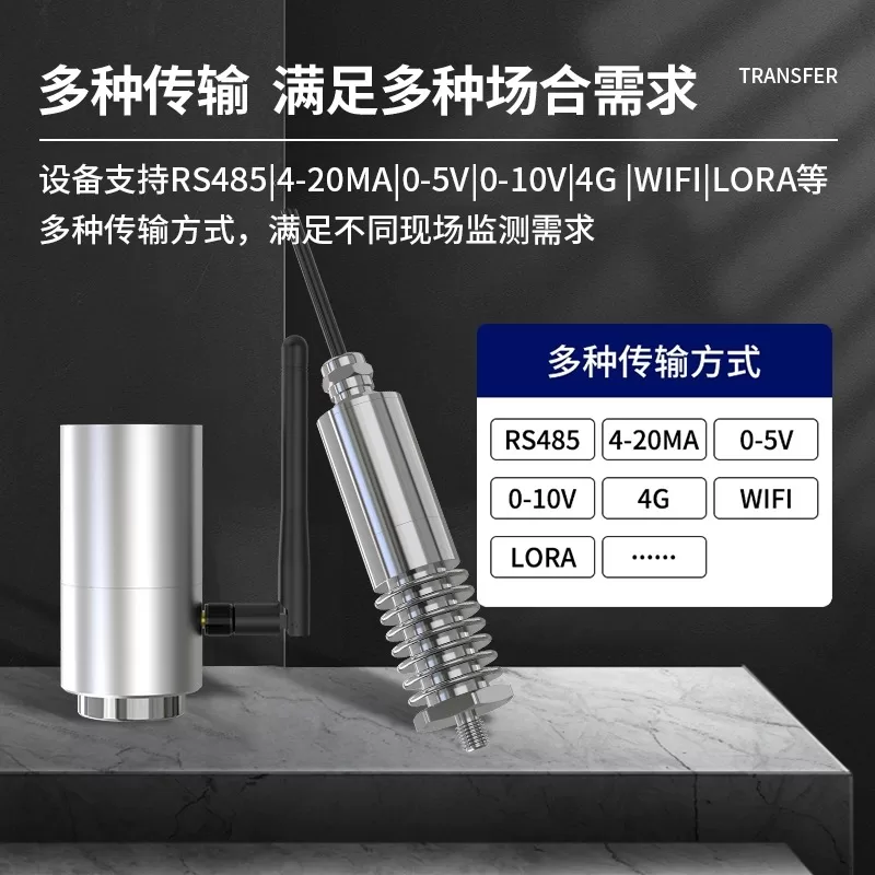
RS-485 |
| Detection cycle |
Real time |
| Default line length |
1.5 meters |
Note: Features marked with "* xxxxxx" are newly added, and some older devices do not have this feature.
Installation Instructions
5.1 Overall Dimensions
Size of old temperature vibration transmitter (some selected transmitters still use the old size)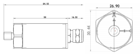 Dimensions of the new temperature vibration transmitter
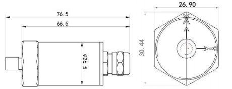 Magnetic suctionM5Threaded version: Based on the dimensions shown in the diagram, the thread will be shortened by 3mm;Equipment List:1 main device
5.2 Installation and Wiring Instructions
1) There are certain specification requirements for 485 line field wiring, please refer to the data package "485 Equipment Field Wiring Manual" for details.Installation InstructionsThis device supports thread installation methods, with thread specifications including M5 × 0.8 × 7, M8 × 1.25 × 10, M10 × 1.5 × 10, and other conventional thread specifications. In addition, there is also a magnetic suction installation method (magnetic suction version is M5 × 0.8 × 7 thread version with magnetic seat).Power supply and 485 signalWide voltage power supply can input 10-30V. When wiring the 485 signal line, be careful not to connect wires A and B in reverse on the busSpecific wiring
|
line color |
Explanation |
| Power supply |
brown |
Positive power supply (10~30V DC) |
| Black |
Power supply negative |
| Communication |
Yellow (Green) |
485-A |
| blue |
485-B |
5.3 Install and use configuration software
Software SelectionOpen the package, select "Debugging Software" ->"485 Parameter Configuration Software", find and open it. Note: When using this configuration software to change the address and baud rate, only one device can be connected.Parameter Settings① Select the correct COM port (check the COM port in "My Computer - Properties - Device Manager - Ports"), and the following figure lists the driver names of several different 485 converters.
485Communication Protocol
6.1Communication Basic Parameters
| Encoding |
8-bit Binary |
| Data Bit |
8-bit |
| Parity Check Bit |
None |
| Stop Bit |
1-bit |
| Error Check |
CRC (Redundant Cyclic Code) |
| Baud rate |
2400~115200 can be set |
6.2Data frame format definition
Using Modbus RTU communication protocol, the format is as follows:Host query frame structure:
| address code |
|
function code |
|
Register starting address |
Register Length |
|
Low bit of verification code |
|
High bit of verification code |
| 1 byte |
|
1 byte |
|
2 bytes |
2 bytes |
|
1 byte |
|
1 byte |
Slave response frame structure:
| Address code |
Function code |
Number of valid bytes |
Data area 1 |
Second data area |
Nth data area |
checksum |
| 1-byte |
1-byte |
1-byte |
2-byte |
2-byte |
2-byte |
2-byte |
6.3Register address description
Note: A new register with the "* xxxxxx" identifier has been added, but some older devices do not have this register.Register Description
| Register Ground |
PLC or group |
Content |
Support function code |
Explanation |
| 0000 H |
40001 |
temperature |
0x03/0x04 |
Temperature measurement value (enlarged by 10 times) |
| 0001 H |
40002 |
speed |
0x03/0x04 |
Velocity measurement value (enlarged by 10 times) |
| 0002 H |
40003 |
Displacement |
0x03/0x04 |
Displacement measurement value (enlarged by 10 times) |
| 0003 H |
40004 |
Acceleration |
0x03/0x04 |
Acceleration measurement value (enlarged by 10 times) * 230510 |
| 0050 H |
40081 |
Temperature calibration value |
0x03/0x04/0x06 |
Integer (enlarged by 10 times) |
| 005C H |
40093 |
Temperature Calibration System |
0x03/0x04/0x10 |
Temperature coefficient A (float) * 230510 |
| 005D H |
40094 |
| 005E H |
40095 |
Temperature calibration system |
0x03/0x04/0x10 |
Temperature coefficient B (float) * 230510 |
| 005F H |
40096 |
| 0068 H |
40105 |
Speed Calibration Value |
0x03/0x04/0x10 |
Speed coefficient A (floating point type) |
| 0069 H |
40106 |
| 006A H |
40107 |
Speed calibration value |
0x03/0x04/0x10 |
Speed coefficient B (floating point type) |
| 006B H |
40108 |
| 0074 H |
40117 |
Displacement calibration value |
|
Displacement coefficient A (floating point type) |
| 0075 H |
40118 |
| 0076 H |
40119 |
Displacement calibration value |
0x03/0x04/0x10 |
Displacement coefficient B (floating point type) |
| 0077 H |
40120 |
| 0080 H |
40129 |
Acceleration Calibration |
0x03/0x04/0x10 |
Acceleration coefficient A (float) * 230510 |
| 0081 H |
40130 |
| 0082 H |
40131 |
Acceleration Calibration |
0x03/0x04/0x10 |
Acceleration coefficient B (float) * 230510 |
| 0083 H |
40132 |
| 07D0 H |
42001 |
Device address |
0x03/0x04/0x06 |
1~254 (factory default 1) |
| 07D1 H |
42002 |
Baud rate |
|
0 represents 2400 |
Register Description
| Register location |
PLC or group |
Content |
Support function code |
Explanation |
| 0000 H |
40001 |
temperature |
0x03/0x04 |
Temperature measurement value (enlarged by 10 times) |
| 0001 H |
40002 |
X-axis velocity |
0x03/0x04 |
X-axis velocity measurement value (enlarged by 10 times) |
| 0002 H |
40003 |
Y-axis velocity |
0x03/0x04 |
Y-axis velocity measurement value (enlarged by 10 times) |
| 0003 H |
40004 |
Z-axis velocity |
0x03/0x04 |
Z-axis velocity measurement value (enlarged by 10 times) |
| 0004 H |
40005 |
X-axis displacement |
0x03/0x04 |
X-axis displacement measurement value (enlarged by 10 times) |
| 0005 H |
40006 |
Y-axis displacement |
0x03/0x04 |
Y-axis displacement measurement value (enlarged by 10 times) |
| 0006 H |
40007 |
Z-axis displacement |
0x03/0x04 |
Z-axis displacement measurement value (enlarged by 10 times) |
| 0009 H |
40010 |
Version Number |
0x03/0x04 |
Version Number |
| 000A H |
40011 |
X-axis Acceleration |
0x03/0x04 |
X-axis acceleration measurement value (expanded by 10) |
| 000B H |
40012 |
Y-axis acceleration |
0x03/0x04 |
Y-axis acceleration measurement value (enlarged by 10) |
| 000C H |
40013 |
Z-axis acceleration |
0x03/0x04 |
Z-axis acceleration measurement value (expanded by 10) |
| 0050 H |
40081 |
Temperature calibration value |
0x03/0x04/0x06 |
Integer (enlarged by 10 times) |
| 005C H |
40093 |
Temperature coefficient A |
0x03/0x04/0x10 |
Temperature coefficient A (float) * 230510 |
| 005D H |
40094 |
|
|
|
| 005E H |
40095 |
Temperature coefficient B |
0x03/0x04/0x10 |
Temperature coefficient B (float) * 230510 |
| 005F H |
40096 |
| 0060 H |
40097 |
X-axis speed calibration |
0x03/0x04/0x10 |
X-axis velocity coefficient A (float) |
| 0061 H |
40098 |
| 0062 H |
40099 |
X-axis speed calibration |
0x03/0x04/0x10 |
X-axis velocity coefficient B (float) |
| 0063 H |
40100 |
| 0064 H |
40101 |
Y-axis speed calibration |
0x03/0x04/0x10 |
Y-axis velocity coefficient A (float) |
| 0065 H |
40102 |
| 0066 H |
40103 |
Y-axis speed calibration |
0x03/0x04/0x10 |
Y-axis velocity coefficient B (float) |
| 0067 H |
40104 |
| 0068 H |
40105 |
Z-axis speed calibration |
0x03/0x04/0x10 |
Z-axis velocity coefficient A (float) |
| 0069 H |
40106 |
| 006A H |
40107 |
Z-axis speed calibration |
0x03/0x04/0x10 |
Z-axis velocity coefficient B (float) |
| 006B H |
40108 |
| 006C H |
40109 |
X-axis displacement calibration |
0x03/0x04/0x10 |
X-axis displacement coefficient A (float) |
| 006D H |
40110 |
| 006E H |
40111 |
X-axis displacement calibration |
0x03/0x04/0x10 |
X-axis displacement coefficient B (float) |
| 006F H |
40112 |
| 0070 H |
40113 |
Y-axis displacement calibration |
0x03/0x04/0x10 |
Y-axis displacement coefficient A (float) |
| 0071 H |
40114 |
| 0072 H |
40115 |
Y-axis displacement calibration |
0x03/0x04/0x10 |
Y-axis displacement coefficient B (float) |
| 0073 H |
40116 |
| 0074 H |
40117 |
Z-axis displacement calibration |
0x03/0x04/0x10 |
Z-axis displacement coefficient A (float) |
| 0075 H |
40118 |
| 0076 H |
40119 |
Z-axis displacement calibration |
0x03/0x04/0x10 |
Z-axis displacement coefficient B (float) |
| 0077 H |
40120 |
| 0078 H |
40121 |
X-axis acceleration |
0x03/0x04/0x10 |
X-axis acceleration coefficient A (float) |
| 0079 H |
40122 |
| 007A H |
40123 |
X-axis acceleration |
0x03/0x04/0x10 |
X-axis acceleration coefficient B (float) |
| 007B H |
40124 |
| 007C H |
40125 |
Y-axis acceleration |
0x03/0x04/0x10 |
Y-axis acceleration coefficient A (float) |
| 007D H |
40126 |
| 007E H |
40127 |
Y-axis acceleration |
0x03/0x04/0x10 |
Y-axis acceleration coefficient B (float) |
| 007F H |
40128 |
Calibration value B |
|
*230510 |
| 0080 H |
40129 |
Z-axis displacement calibration |
0x03/0x04/0x10 |
Z-axis acceleration coefficient A (float) |
| 0081 H |
40130 |
| 0082 H |
40131 |
Z-axis acceleration |
0x03/0x04/0x10 |
Z-axis acceleration coefficient B (float) |
| 0083 H |
40132 |
| 07D0 H |
42001 |
Device address |
0x03/0x04/0x06 |
1~254 (factory default 1) |
| 07D1 H |
42002 |
Baud rate |
0x03/0x04/0x06 |
0 represents 2400 |
6.4 Example and Explanation of Communication Protocol
Example 1: Read the temperature value of device 1Inquiry frame:
| address code |
function code |
|
starting address |
|
data length |
Check code low bit |
Check code high bit |
| 0x01 |
0x03 |
|
0x00 0x00 |
|
0x00 0x00 0x01 |
0x84 |
0x0A |
Response frame:(e.g. device 1 is temperature, real-time value is 8.0 ℃)
| Address code |
Function code |
Return of valid bytes |
Device 1 real-time data |
|
Check code low |
Check code high |
| 0x01 |
0x03 |
0x02 |
0x00 0x50 |
|
0xB8 |
0x78 |
Temperature Calculation:
6.5 Common problems and solutions
Possible reasons why the device cannot connect to the PLC or computer: