
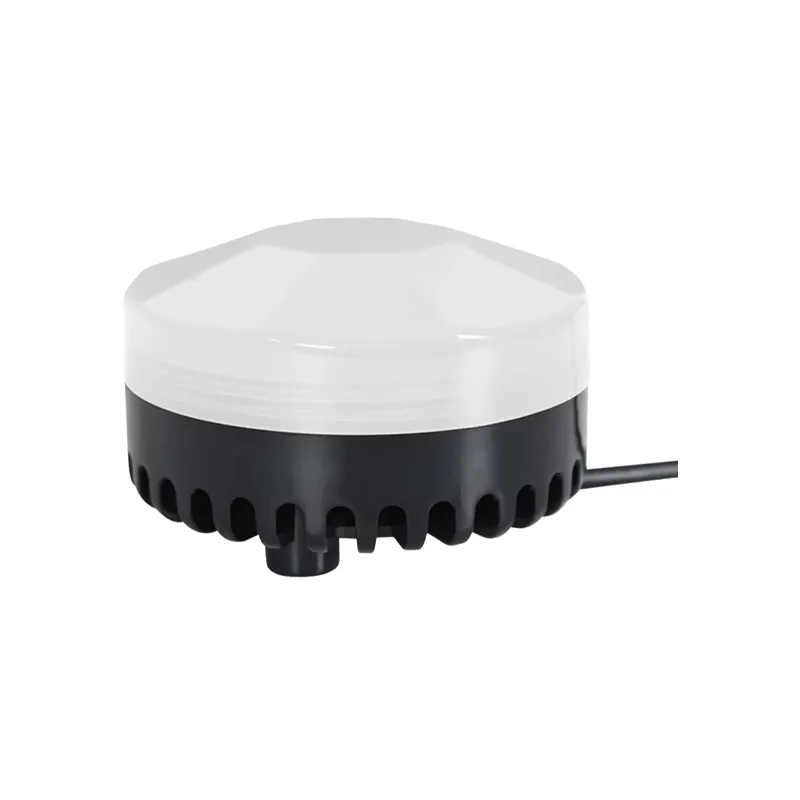
1Product Introduction
This domain allows hosts and terminals to check for errors during transmission. Sometimes, due to electrical noise and other interference, a set of data may undergo some changes on the line when transmitted from one device to another. Error checking can ensure that the host or terminal does not respond to the data that has changed during the transmission process, which improves the security and efficiency of the system. Error checking uses a 16 bit cyclic redundancy method (CRC16).
FF 06 00 CMD DH DL CRC_L CRC_H
(1) Sending this command during playback will loop through the current track. If the device is currently in a paused or stopped state, it will not respond to this command.
DH=0x04,DL=0x01, Indicates that FLASH is playing
When there is no configuration or the configuration is set to 0, the pulse can interrupt the playback function once; Play the voice once the trigger signal is received. If another trigger signal is received during the current playback process, interrupt the current playback and execute a new instruction;
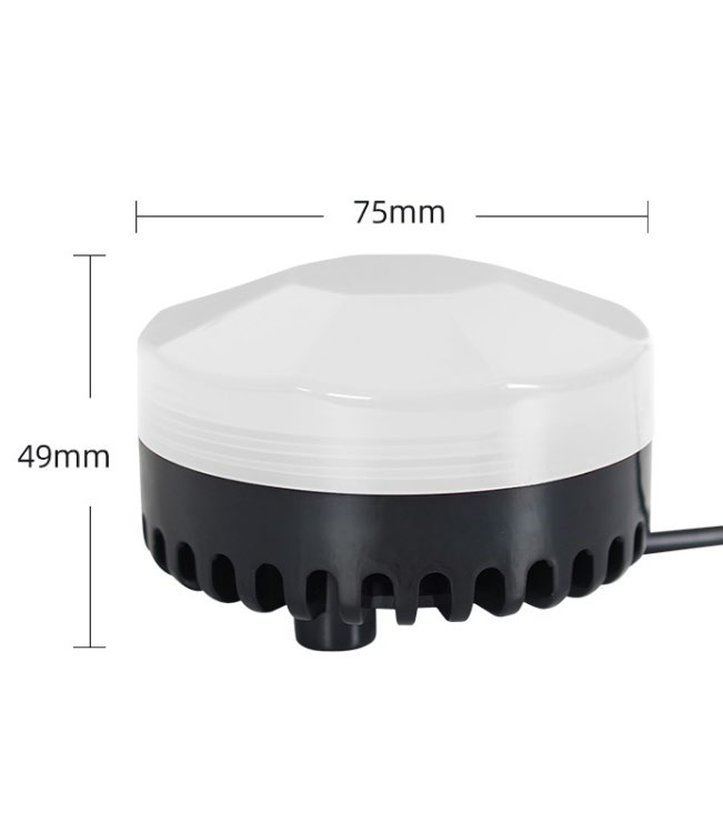
| Product model: YX75R Sound and light alarm | |||
| Rated voltage | DC 9V-30V | Color of police lights | red Yellow, Green, Output power |
| Power supply | 5W (12V Horn impedance, Flashing mode: 8Ω) | Explosion flash | Slow flashing, Long bright, Audio format |
| Format | Mp3 Bit rate (Frequency response≤192Kbps) | Memory capacity | 70HZ~13KHz |
| Default built-in | Flash memory 4M Protection Rating Sound volume | Control mode | IPX65 |
| Three way switch quantity | 0-100db | Serial communication | Serial port description/modbus 485 In industrial control |
3, Electric power communication
Intelligent instruments and other fields, Usually, data exchange is carried out through serial communication, Serial port is a commonly used communication method in the field of control, We have carried out industrial level optimization; Verification of added frames, Resend, Error handling, Other measures, Greatly enhance the stability and reliability of communication At the same time, it can be expanded on this basis, Perform networking functions, This skill modbus 485 Board placement support, Serial communication The default baud rate is modbus485 Due to its binary representation and compact data structure, High communication efficiency 9600.
Modbus RTU Widely used, At work, On site operations are generally adopted. agreement Generally speaking Modbus RTU What everyone is talking about is based on serial communication, Communication protocols all refer to, Communication protocol Modbus Factory default parameters Modbus RTU Default;
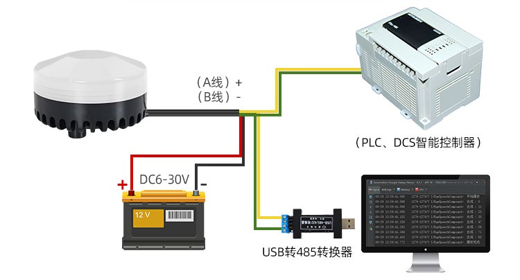
Address: Default volume 485 Default baud rate: 01; wiring 30; Default baud rate:9600; 485 wiring: Yellow A+/Green B- ;
3.1, Communication format
| Modbus RTU Protocol communication application format; Data bits: 8; Stop position: 1; Error detection: CRC (Cyclic redundancy check) | |||||||
| Addr | Fun | Data start reg hi | Data start reg lo | Data #ofregs hi | Data #ofregs lo | CRC16_L | CRC16_H |
| 01 | 06 | 00 | 03 | 00 | 01 | B8 | 0A |
| 485Address | Function Code | Register address high Byte | Low register address Byte | Register data high Byte | Register data low Byte | Verify low characters Festival | Verify high characters Festival |
| Address code (1 Bytes) , Function code (1 Bytes) , Starting address (2 Bytes) , data Bytes (2 Verification code) , Bytes (2 Slave address) | |||||||
Addr: Function code
Fun: Starting address of data
Data start reg hi: Register high byte Starting address of data
Data start reg lo: Register low byte Number of data reads
Data #of reg hi: Register high byte Low byte of data read register
Data #of reg lo: Cyclic redundancy check high byte
CRC16_H: Low byte of cyclic redundancy check
CRC16_L: Instruction format: [Address Code]+[Function Code]+[Register Address High 8 Bits]+[Register Address Low 8 Bits]+[Data High 8 Bits]
[Data low 8 bits]+[Check low 8 bits]+[Check high 8 bits] +
Address code and function code
3.1.1, Address code
The address field is at the beginning of the frame:
Composed of one byte, The hexadecimal number is, The decimal number is 0x00~0xFF;Among them 0~255, For our super address 255 (0xFF) These bits indicate the address of the user specified terminal device. The device will receive from it, Connected host data The address of each terminal device must be unique. Terminals that are only addressed will respond to queries containing that address, inquire inquire. When the terminal sends back a response, The slave address data in the response tells the host which terminal is communicating with it.
Function code:
The functional domain code tells the addressed terminal what function to perform. The following table lists the function codes we commonly use, And their meanings Meaning and function.
| Function code | name | effect |
| 03 | Read and hold registers | Retrieve the current binary value from one or more hold registers |
| 06 | Pre set single register | Load specific binary values into a hold register |
03H Function code: Read data from the specified register, Our product uses this function to read the status of the system, Total number of files, etc data The query function of our product, Function code;
06H Write data into the register: Write the data to be received from the host into the register set by oneself, Our product uses this function when our chip receives instructions sent by the host, The chip stores this instruction, Store in the established register Perform corresponding actions on this instruction again, The control function of our product, Control the alarm light based on the high byte bits of the register address;
3.1.2, The state of D1 Command
| CMD Function code:0X03; Command function: 06H; Designated track playback: Play root directory number, Qu 1 Format | ||||||||
| Instructions | Addr | Fun | Data start reg hi | Data start reg lo | Data #of regs hi | Data #of regs lo | CRC_L | CRC_H |
| Address | 01 | 06 | 00 | 03 | 00 | 01 | B8 | 0A |
| 485 Function code | Register address | High byte Register address | Low byte Number of registers | According to high byte Number of registers | According to low byte Verify low characters | Festival Verify high characters | Festival Control the flashing mode and color of the alarm light through the high byte bits of the register address | |
(1) , At the same time, as long as the playback is completed, Alarm lamp, The control state will be restored to default D1 Instruction format;
In the instruction: FF 06 XY CMD DH DL CRC_L CRC_H
Parameters that control the flashing mode and color of the alarm light: XY The specific numerical values correspond to the states shown in the table below, The specific numerical values correspond to the states shown in the table below;
CDM express 06H Control instructions, Numerical referenceInstruction table; DH DL Indicate the corresponding numerical value of the instruction;
example: send out: FF 06 11 03 00 01 A8 E8 Specify to play the first song, The red light is always on
(2) Register address high byte value XY Corresponding warning lights D1 State value parameter table:
| X Inputable values | Corresponding functions | Y Inputable values | Corresponding functions |
| 1 | The police light is always on | 1 | red light |
| 2 | The police light flashes slowly | 2 | Yellow light |
| 3 | The police light is flashing | 3 | Green light |
| 6 | The police light goes out | 0 | No lights on |
Note For: XY Time 00 At this time, the state of the light during playback is the same as the state during the last playback, The default alarm light status is off when powered on again, Reference instructions;
Instructions:
| express (xx xx Verification CRC explain) | Play |
| FF 06 31 0F 01 01 xx xx | folder01Qu001Red light flashing, Play |
| FF 06 23 0F 01 02 xx xx | folder01Qu002Green light flashing slowly, Play |
| FF 06 12 0F 02 01 xx xx | folder02Qu001The yellow light is always on, Play |
| FF 06 60 0F 02 02 xx xx | folder02Qu002The police light goes out, Error verification field |
3.1.3, This domain allows hosts and terminals to check for errors during transmission
Sometimes due to electrical noise and other interferences. A set of data from one, When a device transfers to another device, there may be some changes on the line Error verification can ensure that the host or terminal does not respond, The data that has changed during the transmission process This improves the security and efficiency of the system, Error verification was used, Bit cycle redundancy 16 Bit cycle redundancy The remaining methods (CRC16) .
Methods for error detection:
Error verification (CRC) The domain occupies two bytes, Contains one 16 The binary value of a bit. CRC The value is calculated by the transmission device, Then attach it to the data frame, The receiving device recalculates when receiving data CRC Value, And then with the received CRC Compare the values in the domain Compared, If these two values are not equal, An error occurred.
CRC During computation, Firstly, one 16 The register of bits is pre-set to full 1, Then continuously extract each byte in the data frame 8 Position Perform operations on the current value of the register, Only for each byte 8 One data bit is involved in generation CRC, Starting and ending positions And also possible The parity bits that can be used are not affected CRC. Generating CRC Time, Each byte 8 XOR the contents of the bit and register, Then Shift the result to a lower position, Use high positions“0”Supplement, Lowest position (LSB) Remove and inspect, If it is 1, This register is associated with a pre Fixed value set (0A001H) Perform an XOR operation, If the lowest position is 0, Do not take any action.
The above processing is repeated, Until the execution is completed 8 Secondary shift operation, When the last one (The 8 Position) After relocation, next 8 Position XOR the byte with the current value of the register, Similarly, perform another one as mentioned above 8 Secondary shift XOR operation, When all in the data frame All bytes have been processed, The final value generated is CRC Value.
The above only explains CRC16 The calculation method and function of cyclic redundancy check, If you don't understand, you can ignore this part, Usually this verification We can hand over the code to the software for calculation, and there is no need to calculate it ourselves, It's okay if you don't understand, I won't go into detail here, Please refer to relevant materials for details.
3.2, Serial port instruction table
| CMDCommand | Function | Instructions sent (16 Binary characters) | Remarks and explanations |
| Control instructions (06H) | |||
| 0x0F | Specify the folder file name for playback | FF 06 00 0F 02 07 xx xx | Specify the 02 folder 07 Track playback |
| FF 06 00 0F 0F FF xx xx | Specify the 15 folder 255 Track playback | ||
| FF 06 11 0F 01 01 xx xx | Broadcast 01 folder 01 Qu, The red light is always on | ||
| FF 06 22 0F 63 FF xx xx | Broadcast 99 folder 255 Qu, The yellow light flashes slowly | ||
| 0x01 | Next song | FF 06 00 01 00 00 xx xx | Play the next track of the current track |
| 0x02 | Previous song | FF 06 00 02 00 00 xx xx | Play the previous track of the current track |
| 0x03 | Designated track | FF 06 00 03 00 01 xx xx | Root directory physical order first song |
| FF 06 12 03 00 02 xx xx | Root directory second track, The yellow light is always on | ||
| FF 06 31 03 00 02 xx xx | Root directory second track, Red light flashing | ||
| 0x04 | Volume increase | FF 06 00 04 00 00 xx xx | Volume increase |
| 0x05 | Volume reduction | FF 06 00 05 00 00 xx xx | Volume reduction |
| 0x06 | Specify the volume | FF 06 00 06 00 1E xx xx | Set the volume to 30 |
| 0x08 | Single loop designated track | FF 06 00 08 00 01 xx xx | Loop play the first song |
| 0x09 | Specify the playback device | FF 06 00 09 00 01 xx xx | Specify the playback device-U Plate |
| FF 06 00 09 00 04 xx xx | Specify the playback device-FLASH | ||
| 0x0B | Set the baud rate | FF 06 00 0B 00 01 xx xx | Set the device baud rate to 9600 |
| 0x0C | Chip reset | FF 06 00 0C 00 00 xx xx | Chip reset |
| 0x0D | Play | FF 06 00 0D 00 00 xx xx | Play tracks |
| 0x0E | Pause | FF 06 00 0E 00 00 xx xx | Pause playback |
| 0x10 | Specify folder file name loop | FF 06 00 10 01 01 xx xx | 01 folder 001 Curved cycle |
| FF 06 00 10 02 01 xx xx | 02 folder 001 Curved cycle | ||
| 0x11 | Loop through all tracks | FF 06 00 11 00 01 xx xx | Cycle activation |
| FF 06 00 11 00 00 xx xx | Loop closure | ||
| 0x16 | stop it | FF 06 00 16 00 01 xx xx | Stop the current playback |
| 0x17 | Specify folder loop playback | FF 06 00 17 00 01 xx xx | appoint 01 Loop playback of folders |
| 0x18 | Random playback | FF 06 00 18 00 00 xx xx | Designate the entire device to play randomly |
| 0x19 | The current playing track plays in a loop | FF 06 00 19 00 00 xx xx | Set the current playing track loop |
| Stop the current track loop | FF 06 00 19 00 01 xx xx | Stop the current playing track loop | |
| 0xC0 | Set the device address | FF 06 00 C0 00 01 xx xx | The device address is set to 01 |
| FF 06 00 C0 00 63 xx xx | The device address is set to 99 | ||
| 0xC2 | Turn on the alarm light separately D1 | FF 06 00 C2 00 11 xx xx | The red light is always on, Do not change the current playback status |
| FF 06 00 C2 00 23 xx xx | Green light flashing slowly, Do not change the current playback status | ||
| FF 06 00 C2 00 32 xx xx | Yellow light flashing, Do not change the current playback status | ||
| FF 06 00 C2 00 60 xx xx | Turn off the flashing lights | ||
| Report that the warning light has turned off | FF 06 60 03 00 01 xx xx | Play the first song, Alarm lamp D1 Not lit up | |
| Query instruction (03H) | |||
| 0x3F | Search for online devices | FF 03 00 3F 00 00 xx xx | Take a closer look4.2.1 |
| 0X42 | Query the current playback status | FF 03 00 42 00 00 xx xx | Take a closer look4.2.2 |
| 0X43 | Query the current volume | FF 03 00 43 00 00 xx xx | Take a closer look4.2.3 |
| 0X49 | Query the number of device files | FF 03 00 49 00 00 xx xx | Take a closer look4.2.4 |
| 0x4D | Query the current playing track | FF 03 00 4D 00 00 xx xx | Take a closer look4.2.5 |
| 0X70 | Query the sound and light status of the current device | FF 03 00 70 00 00 xx xx | Take a closer look4.2.6 |
| 0xFE | Query software version number | FF 03 00 FE 00 00 xx xx | |
| xx xx For CRC Verification, FF For super addresses, Can be modified to the corresponding device address; (Instructions are for reference only, Please modify according to your needs) | |||
4, Detailed explanation of serial port control instructions
Below, we will provide a detailed explanation of some commonly used instructions
Annotation: The instruction format is:
Address code + Function code + High byte starting address + Low byte starting address + High byte data + Low byte data + CRC Verification
FF 06 00 CMD DH DL CRC_L CRC_H
FF For super addresses, Corresponding equipment485Address, Factory default address01; CMD Representing opcodes,CRC_L, CRC_H For cyclic redundancy calibration
Testing, Among the following instructions DH, DL For input values, Enter the corresponding numerical value as requested by the user; Note that all instruction values are16Binary numerical value;
4.1, Description of commonly used control instructions
4.1.1, Specify the folder file name for playback (0x0F)
Instruction format: FF 06 00 0F DH DL CRC_L CRC_H
DH:Represents the name of the folder, Default support 99 A folder, That is 01~99 Naming; DH=0x01~0x63; DL:Represents the track, default maximum 255 A song, That is 001~255; DL=0x01~0xFF
Example: 01 06 00 0F 02 01 79 69 Specify playback 02 folder 001 Songs
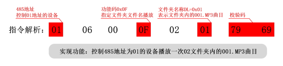
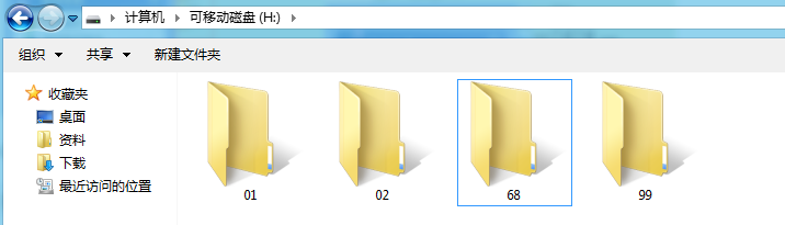
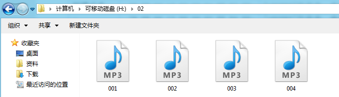
(1), Designated folder playback is an extended feature we have developed, The default folder naming format is: “01 ”…“99”’, Inside the folder The naming format for the track is:: “001xxx.mp3 ”…“255xxx.mp3 ”;Default maximum support for each folder 255 A song, At most support 99 A folder;
(2), Both the folder and file name must be specified, To lock a file; Designated folders and designated tracks are supported MP3, WAV Two types Format;
(3), The following two figures illustrate the specification of folders and file names [as shown in the figure], please strictly follow our instructions to name folder file names;
reference instructions:
| instructions (xx xx representations CRC verifications) | explanations |
| FF 06 00 0F 01 01 xx xx | play folders01play folders001xxx.mp3 |
| FF 06 00 0F 01 63 xx xx | play folders01play folders099xxx.mp3 |
| FF 06 00 0F 63 FF xx xx | specify song playback instructions99the instructions we provide support the playback of specified songs255xxx.mp3 |
4.1.2, the selection range of songs is (0x03)
The instructions we provide support the playback of specified tracks, The selection range of songs is 0~3000, Actually, it can support more, Because For reasons related to file management, Supporting too many songs, Will cause slow system operation, Ordinary applications do not need to support so many The document. This instruction is specified in the physical order of storage, FLASH Default to root directory.
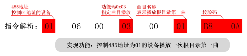
(1), For song selection, If the option is chosen 100 First, Firstly, we will 100 Convert into 16 Binary, default is double byte, which is 0x0064. DH = 0x00 ; DL = 0x64
Instruction format: FF 06 00 03 DH DL CRC_L CRC_H
Example: 01 06 00 03 00 01 B8 0A
DH DL Indicate the sequence parameter of the songs to be played
Specify to play the first song from the root directory;
Reference instructions:
| Instructions (xx xx express CRC Verification) | explain |
| FF 06 00 03 00 01 xx xx | Play the first song in physical order |
| FF 06 00 03 00 63 xx xx | Play in physical order99Qu |
| FF 06 00 03 00 FF xx xx | Play in physical order255Qu |
| FF 06 00 03 0B B8 xx xx | Play in physical order3000Qu |
4.1.3, Specify device volume command (0x06)
(1) , The default volume of our amplifier board is 30, Jointly 30 Level volume, If you want to set the volume, simply send the corresponding command; (2) , When the device receives a command, the indicator light will flash once, At the same time, it will return the same data;
(3) , The command to set the volume will be reset when the device restarts, If power off memory is required, the volume can be set through the configuration file;
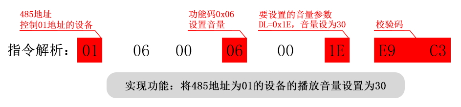
Instruction format: FF 06 00 06 00 DL CRC_L CRC_H
Example: 01 06 00 06 00 1E E9 C3
DL Parameters for the volume to be set, Turn the volume to be set Replace with 16 Binary number, Input into DL Location;
Set the software volume to 30;
Reference instructions:
| Instructions (xx xx express CRC Verification) | explain |
| FF 06 00 06 00 00 xx xx | Set the current device volume to0 (Mute) |
| FF 06 00 06 00 19 xx xx | Set the current device volume to25 |
4.1.4, Set the serial port baud rate (0x0B)
(1) , The default baud rate of the power amplifier board at the factory is 9600; If you need to change the baud rate, Can be used 0x0B Instruction modification;
(2) , After setting the baud rate, Please wait 1 second, Send reset again[0x0C Instructions], Or power off and restart to take effect; (3) , After setting the baud rate, The device will remember, Restarting the device will change the baud rate to the set value;
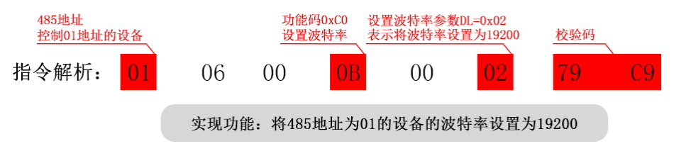
Instruction format: FF 06 00 0B 00 DL CRC_L CRC_H DL Parameters for the baud rate to be set, Please refer to the table below for details;
| DL Parameters | Corresponding baud rate | DL Parameters | Corresponding baud rate |
| 0x01 | 9600 | 0x05 | 115200 |
| 0x02 | 19200 | 0x06 | 256000 |
| 0x03 | 38400 | 0x07 | 35250 |
| 0x04 | 57600 | 0x09 | 4800 |
Example: 01 06 00 0B 00 02 79 C9 Set the baud rate for serial communication to 19200bps;
| Instructions (xx xx express CRC Verification) | explain |
| FF 06 00 0B 00 01 xx xx | Set the device baud rate to9600 |
| FF 06 00 0B 00 03 xx xx | Set the device baud rate to38400 |
4.1.5, Specify the folder to start looping playback (0x17)
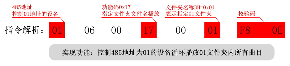
Instruction format: FF 06 00 17 00 DL CRC_L CRC_H DL:Represents the name of the folder, Default support 99 One
Document folder, That is 01 ~ 99 Naming; DL=0x01~0x63;
(1) , The naming convention for folders must be:“01 ” Arrived “99 ”,Cannot exceed 99;Naming convention reference4.1.4;
(2) , Once the folder loop is specified, Can use play/pause/previous/next track. These operation commands will not interrupt when
Loop playback status of the previous folder. in other words, After sending the next song command, It will still loop through the current folder. (3) , Users can send a stop command to end the loop playback, Return to the triggered playback state.
(4) , After playing each song in a loop, there will be a return data, Corresponding to the recently played track;
Example: 01 06 00 17 00 01 F8 0E appoint 02 Loop playback of folders;
Reference instructions:
| Instructions (xx xx express CRC Verification) | explain |
| FF 06 00 17 00 01 xx xx | 01Loop playback of folders |
| FF 06 00 17 00 63 xx xx | 99Loop playback of folders |
4.1.6, Set the current track to loop play (0x19)
Instruction format: FF 06 00 19 00 DL CRC_L CRC_H DL=0x00, Loop playback enabled; DL=0x01, Loop playback is turned off;
Example: send out: FF 06 00 19 00 00 4D D3 DL=0x00 Cycle activation;
send out: FF 06 00 19 00 01 8C 13 DL=0x01 Loop closure;
(1) , Send this command during playback, It will play the current track in a loop. If it is currently in a paused or stopped state, Then The device will not respond to this command.
(2) , If you want to turn off the single loop playback, Just send the command to close, This will stop playing the current track after it is played.
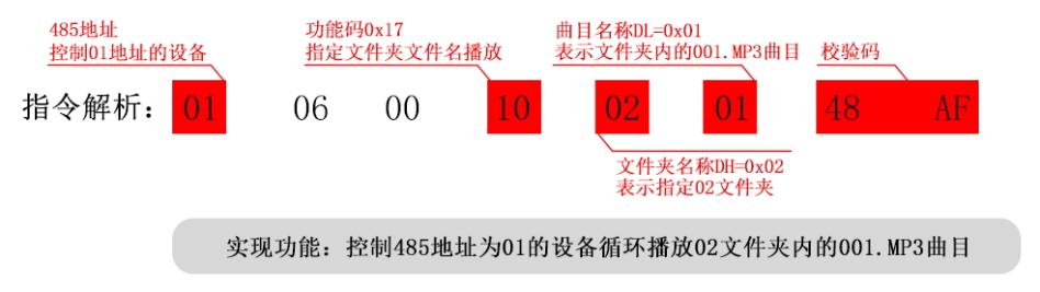
4.1.7, Specify folder file name for loop playback (0x10)
Instruction format: FF 06 00 10 DH DL CRC_L CRC_H
DH:Represents the name of the folder, Default support 99 A file, That is 01 ~ 99 Naming; DH=0x01~0x63; DL:Represents the track, default maximum 255 A song, That is 001~255; DL=0x01 ~ 0xFF
(1), Designated folder playback is an extended feature we have developed, The default folder naming format is: “01 ”…“99”’, Inside the folder The naming format for the track is:: “001xxx.mp3 ”…“255xxx.mp3 ”;Default maximum support for each folder 255 A song, At most support 99 A folder;
(2), Both the folder and file name must be specified, To lock a file; Designated folders and designated tracks are supported MP3, WAV Two types Format;
(3), The following two figures illustrate the specification of folders and file names [as shown in the figure], please strictly follow our instructions to name folder file names;
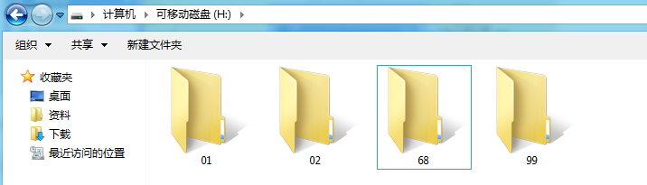
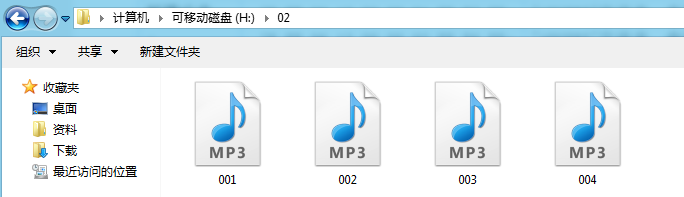
example: 01 06 00 10 02 01 48 AF specification“02 ”folder 001xxx.MP3 file loop playback
reference instructions:
| instructions (xx xx representation CRC verification) | explanation |
| FF 06 00 10 01 01 xx xx | loop playback folder01loop playback folder001xxx.mp3 |
| FF 06 00 10 01 63 xx xx | set device address01instruction format]099xxx.mp3 |
| FF 06 00 10 63 FF xx xx | Loop play folder99of255xxx.mp3 |
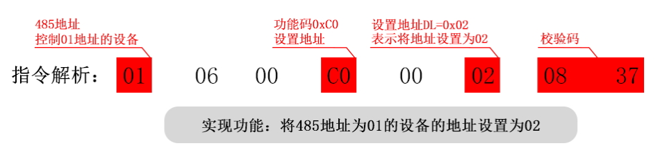
4.1.8, Set device address(0xc0)
Instruction format: FF 06 00 C0 00 DL CRC_L CRC_H
Example: 01 06 00 C0 00 02 08 37
DL Indicate the address that needs to be modified, Can be set 0~254 (Need to transfer Replace with 16 Binary number) And DL=0x00~0xFE;
set up 485 The address is 02;
Reference instructions:
| Instructions (xx xx express CRC Verification) | explain |
| FF 06 00 C0 00 01 xx xx | set up485The address is01 |
| FF 06 00 C0 00 63 xx xx | set up485The address is99 |
| FF 06 00 C0 00 F7 xx xx | set up485The address is247 |
(1) , Send instruction settings 485 After the address, The address will take effect immediately, And it can be powered off for memory;
(2) , The range of address settings is: 1~254, So in the instructions DL What is the range of values that can be inputted 0x01~0xFE;
(3) , After setting the address, It's like giving each device a name, This allows for individual control of a specific address through instructions Equipment, Details can be found at 485 The principle;
(4) , Our device also supports passing through TXT Configure file setting address, And prioritize the configuration file, For details, please refer to the configuration instructions;
4.1.9, Independently control the sound alarm
Independently control the sound alarm, The police light is not on:
Instructions: FF 06 60 CMD DH DL CRC_L CRC_H
example: send out: FF 06 60 0F 01 01 72 47
receive: FF 06 60 0F 01 01 72 47
CMD Representing opcodes, Details for referenceInstruction tableControl instruction section 60: Turn off the warning lights on behalf of, Details for reference3.1.2;
Control the playback of the power amplifier board 01 folder 001 Songs, The police light is not on;
At this point, the amplifier board will play the stored data 01 folder 001 Qu, The alarm light is in the off state;
Instructions: FF 06 60 0F 01 01 72 47; We pass through“Register address high byte”Set the current alarm status of the power amplifier board, Number
Value input 60 It means that the current playback does not turn on the alarm light, Only broadcasting voice messages, The same applies to other control instructions;
Reference instructions:
| Instructions (xx xx express CRC Verification) | explain |
| FF 06 60 03 00 02 xx xx | Play02Songs, The police light is currently off |
| FF 06 60 0F 01 02 xx xx | Play01folder02Songs, The police light is currently off |
| FF 06 60 18 00 00 xx xx | Random playback, The police light is currently off |
| FF 06 60 19 00 00 xx xx | Loop play the currently playing track, The police light is in the off state |
4.1.10, Control the light alarm separately(0xC2)
Instructions: FF 06 00 C2 00 XY CRC_L CRC_H X Control the output mode of the representative police light; Y Representing the color of the police light;
| X Inputable values | Corresponding functions | Y Inputable values | Corresponding functions |
| 1 | The police light is always on | 1 | red light |
| 2 | The police light flashes slowly | 2 | Yellow light |
| 3 | The police light is flashing | 3 | Green light |
| 0 | No lights on |
(1) , Control the light alarm separately(0xC2)The instruction is to independently control the working status of the alarm light, Does not affect the current playback status of the voice;
(2) , After receiving the instruction to control the light alarm separately, the board, The police light will remain on as instructed, To turn off the alarm light, a command must be sent to turn it off
Turn off or send other instructions to change the working status of the alarm light;
(3) , When Y The value is 0 Time, The police light is turned off, If sent FF 06 00 C2 00 60 3C 24 The command can control the turn off of the warning light, no Affects current playback
Reference instructions;
Instructions:
| express (xx xx Verification CRC explain) | The red light is always on |
| FF 06 00 C2 00 11 xx xx | The yellow light is always on |
| FF 06 00 C2 00 12 xx xx | The yellow light is always on |
| FF 06 00 C2 00 13 xx xx | Green light is always on |
| FF 06 00 C2 00 21 xx xx | Red light flashing slowly |
| FF 06 00 C2 00 22 xx xx | The yellow light flashes slowly |
| FF 06 00 C2 00 23 xx xx | Green light flashing slowly |
| FF 06 00 C2 00 31 xx xx | Red light flashing |
| FF 06 00 C2 00 32 xx xx | Yellow light flashing |
| FF 06 00 C2 00 33 xx xx | Green light explosion Flash |
| FF 06 00 C2 00 60 xx xx | The police light is turned off |
| The above instructions can independently control the warning lights to perform corresponding warning actions, Do not change the current voice playback status; | |
4.2, Detailed explanation of serial port query instructions
We will provide detailed explanations of the key areas below--Regarding query instructions:
4.2.1, Query the current online devices(0x3F)
Send instructions: FF 03 00 3F 00 00 60 18 Search for online devices, CMD=0x3F;
Return to receive: 01 03 02 60 08 91 82 0x08, express FLASH on-line;
During the operation of the chip, Continuously monitor the online status of the equipment, Users can access it through 0x3F This command is used for querying, Return number According to the middle address bit 0x01 Indicates that the current device address is 01;
4.2.2, Play status query command (0x42)
Send instructions: FF 03 00 42 00 00 F0 00
Return to receive: 01 03 02 04 01 7B 44
01 03 02 04 02 3B 45
01 03 02 04 00 BA 84
Query the current playback status of the power amplifier board, CMD=0x42
DH=0x04,DL=0x01, express FLASH Playing
DH=0x04,DL=0x02, express FLASH Paused during playback DH=0x04,DL=0x00, express FLASH Stop playing status
| Return data DL The value | Corresponding power amplifier board status |
| 0x00 | The power amplifier board is currently in a stopped playback state |
| 0x01 | The power amplifier board is currently in playback mode |
| 0x02 | The power amplifier board is currently in a paused playback state |
(1) , During the decoding process, the control chip will have 3 The status is open to users. Users can query the current status of the chip through instructions (2) , Play pause refers to, A song is currently playing, Manually sending instructions to pause playback, Play stop refers to, Play a song complete, The chip is in a playback stop state;
(3) , Return the address bit in the data 0x01 Indicates that the current device address is 01;
4.2.3, Query volume (0x43)
Send instructions: FF 03 00 43 00 00 A1 C0
Return to receive: 01 03 02 A1 1E 41 DC
Query the current volume of the amplifier board, CMD=0x43;
The current volume is 30 Grade, DL=0x1E;
Return the data DL Position is the volume value of the current amplifier board, Take it 16 Convert binary numbers to 10 The base number is the current volume, Example: Like 0x1E Convert to 10 The base system is 30, The current volume represented is 30; Return the address bit in the data 0x01 Indicates that the current device address is 01;
4.2.4, FLASH Total number of files (0x49)
Send instructions: FF 03 00 49 00 00 81 C2
Return to receive: 01 03 02 00 08 B9 82
Query the power amplifier board FLASH Total number of files;
Current power amplifier board FLASH The total number of files is 8 One;
Return the data DH,DL Position represents the power amplifier board FLASH Total number of files, Take it 16 Convert binary numbers to 10 The base number is the current Power amplifier board FLASH Total number of files, For example DH=0x00, DL=0x07 Convert to 10 The base system is 07, The current power amplifier board represented FLASH General text The number of items is 7 One, We usually don't store so many files, So look DL Numerical values are sufficient; Return the address bit in the data 0x01 Indicates the current setting The backup address is: 01;
4.2.5, FLASH Current track (0x4D)
Send instructions: FF 03 00 4D 00 00 C0 03
Return to receive: 01 03 02 00 02 39 85
Query FLASH Current track;
The second song in physical order is currently playing or has finished playing;
Return the data DH,DL The track that is currently being played or has been played by the amplifier board, Take it 16 Convert binary numbers to 10 Base system The number is the currently playing track (Physical sequence) , For example DH=0x00, DL=0x02 Convert to 10 The base system is 02, The current track represented is The Second Song of Physical Sequence, We usually don't store so many files, So look DL Numerical values are sufficient; Return the address bit in the data 0x01 express The current device address is 01;
4.2.6, Query the current sound and light status (0x70)
Send instructions: FF 03 00 70 00 00 51 CF
Return data: 01 03 02 DH DL CRC_L CRC_H
For example, returning to receive: 01 03 02 00 12 38 49
Query the current sound and light status
The returned data contains devices 485 Address, Play tracks or status, Flash
Information on the status and color of the lamp;
Currently 485 The address is 01; DH=0x00, Indicates that it is not currently playing Voice; DL=0X12, Indicates that the alarm light is in a constant yellow light state;
Return data, The address bit represents the current situation 485 Address, DH Indicate the sound state, DH The numerical value represents the currently playing track (Physical sequence) , Like DH=0x01 Indicates that the first physical sequence song is currently being played, DH The value range is 0x00~0xFF,Support queries The maximum range is 1~255 A song, When DH=0x00 When it indicates that there is currently no voice being played; DL Representing the state of light, Like
DL=0x11 Indicates that the current light status is a constant red light, DL The corresponding numerical states are shown in the table below:
| DL Numerical value | Corresponding lamp status | DL Numerical value | Corresponding lamp status |
| 11 | The red light is always on | 23 | Green light flashing slowly |
| 12 | The yellow light is always on | 31 | Red light flashing |
| 13 | Green light is always on | 32 | Yellow light flashing |
| 21 | Red light flashing slowly | 33 | Green light flashing |
| 22 | The yellow light flashes slowly | 10/20/30/60/06…Wait | The light goes out |
| Return values that are not listed above, The light status should be in the off state; If the instruction sent does not indicate the status of the light Row settings, It may cause the returned data to not correspond to the actual status of the light, Please refer to the settings for the light status3.1.2; | |||
5, Replace voice files and configuration files
5.1, Replace device voice files
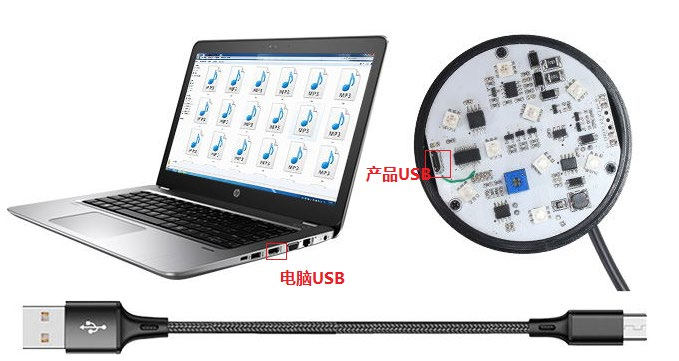
This product is built-in with Micro USB Interface; After unscrewing the lampshade, it can pass through Micro USB Line and PC End connection, Can be freely replaced as needed The voice file to be broadcasted, Operation method and U Similar to disk;
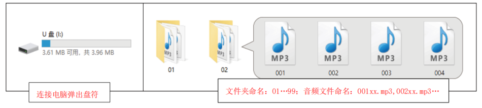
| Precautions for voice replacement: |
| 1, The playback order of multiple voices is based on the time sequence of voice file replacement, Not in file name order; When replacing Please copy them one by one to the disk in the playback order you need; |
| 2, It is best to format the disk once before replacing your own voice files, Copy the file again, Avoiding hidden issues The file caused playback errors; |
| 3, The voice file needs to be MP3 Format, And it must be a sampling rate supported by the product, Does not support product sampling rate MP3 The file format is acceptable Can't play. Product supports sampling rate(KHz):8/11.025/12/16/22.05/24/32/44.1/48; |
| 4, Please disconnect the power supply of the prompt device before connecting the computer to replace the voice, After replacing the voice, it is necessary to disconnect from the computer before giving a prompt Power on the device; |
| Note: If you need to read files by folder file name, Can create a folder named 01, 02…99 Wait, Name of voice files in the folder The name is 001.MP3…255.MP3 Wait, use 0x0F Instructions can be used to read by folder file name; For example: send out 7E FF 06 0F 00 01 01 EF Specify playback 01 Inside the folder 001.MP3 Songs Details for reference “Specify the folder file name for playback”explain; |
5.2, Configuration file description
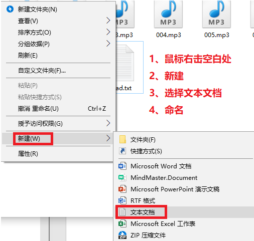
1, The configuration file format must be a text document format (txt Format) , Only in this way can it be recognized by the system, Other file format systems Not recognized, Please strictly follow the method of configuring parameters provided by us.
2, The configuration file is on the same device, There can only be one at most, There may not be (When not configured, it defaults to pulse interruptible mode) , But there must not be two or more, Otherwise, it may lead to recognition errors.
3, Please store the configuration file in the root directory;
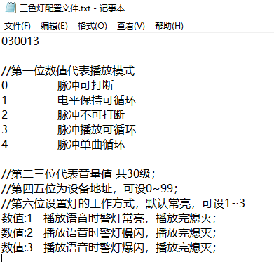
4, Configuration files can be configured 6 Bit value:
The 1 The position represents the function of the button, set up 7 The function of a button, Default can be set 0~4 Jointly 5 Trigger playback mode, Not set
Default setting 0 pattern; (This is the button function setting, The default for serial port control is 0 Just enough, Without further elaboration; ) The 2, 3 Position represents setting the volume, Can be set up 1~30 Jointly 30 Level volume, When not set, it defaults to 30;
The 4, 5 The location is the device address, Can be set up 0~99; (set up 485 Serial communication address; ) Do not set default settings 01;
The 6 Set the flashing mode of the alarm light based on the numerical value, Can be set up 1~3 There are three ways in total;
| Key function configuration value table (First place configuration) | ||
| Numerical value | Corresponding functions | explain |
| 0 | Pulse can be interrupted | No configuration or configuration settings 0 Time, The pulse can interrupt the playback function once; Play once the trigger signal is received Voice once, If during the current playback process, Received other triggering signals, Interrupt the current playback, Go ahead and execute the new Instructions; |
| 1 | The level can be kept cyclic | Configuration settings 1, To maintain the level loop playback function; The trigger signal keeps playing the single loop continuously That voice along the way, Stop playing immediately when the trigger signal disappears; If other triggers are received during the playback process Signal, It will interrupt the current playback, Execute new instructions; |
| 2 | Pulse cannot be interrupted | Configuration settings 2, To ensure uninterrupted pulse function; Play the voice once the trigger signal is received, Broadcast Receiving the signal again during the playback process will not interrupt the playback, Triggering in playback mode will not interrupt playback; |
| 3 | Pulse playback can be looped | Configuration settings 3, To ensure uninterrupted pulse cycle function; Play the voice once the trigger signal is received, Like If the trigger signal remains constant, the voice of that single track will continue to be played in a loop, If the trigger signal disappears, it will be broadcasted Stop playing the voice after playing that session; Receiving the signal again during the playback process will not interrupt the playback; |
| 4 | Pulse single loop | Configuration settings 4, For the pulse single loop function; Once a trigger signal is received, the single track will loop through the voice of that channel, Again Stop playing once the signal is received; If other triggering signals are received during the loop playback process, Will fight Interrupt the current playback, Execute new instructions; (Press the single loop, Press stop again; During the playback process, Press it It switches to playing the corresponding key track when pressed) ; |
| Configuration 6 Position (Set the alarm light status) | |
| Numerical value | Corresponding functions |
| 1 | The alarm light is constantly on during playback, Turn off after playing |
| 2 | The alarm light status is flashing slowly with the playback, Turn off after playing |
| 3 | The alarm light status is flashing with playback, Turn off after playing |
| The button function and alarm light status for configuring the first and sixth numerical settings are only valid for triggering switch values, 485 The serial control version can be ignored! | |
6, Wiring installation
Wiring reference:
(1) , High level trigger wiring for switch quantity:
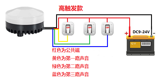
(2) , Low level trigger wiring for switch quantity:
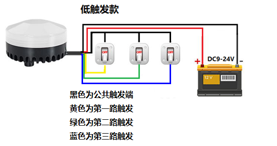
The alarm is triggered by a high/low level switch in multiple triggering modes, This method is commonly used for connecting PLC Automatic alarm or connected to normally open mode Close it for easy manual control of different sounds;
Regarding the high and low level triggering methods:
Our switch triggered control products are divided into two types: high-level triggered control and low-level triggered control, Two products are out of touch The way of sending is different, All other functions are consistent;
High level triggering: High level triggering refers to the triggering method where there is a voltage between the signal input terminal and ground, It can be understood as a signal input terminal And with VCC A way of triggering positive electrode short circuit; The high trigger trigger signal voltage is 3.2V±0.5V~24V; (The trigger end needs to be connected to ours Product co location (Common negative electrode) )
Low level triggering: Low level triggering refers to the voltage between the signal input terminal and ground being 0V The triggering method, It can be understood as a signal Input end and GND A triggering method for negative short circuit; The trigger signal voltage for low voltage models is 0V~ 0.7V±0.1V; (Trigger end required To coexist with our products (Common negative electrode) )
(3) , Modbus 485 Serial communication wiring:
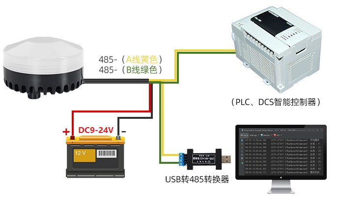
Modbus 485 Serial communication model
Precautions for using power supply:
Please use direct current for the power supply 6V Arrived 30V (Rated current≥1A) DC power supply, Strictly connect the positive and negative poles Line, Please do not reverse, Do not touch conductive liquids in the wiring section; Do not use higher than 30V Voltage or alternating current, Like
Improper use of voltage, There may be a risk of product burning, fire, or personal injury!
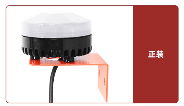
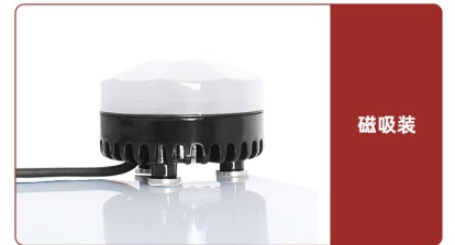
Installation reference:
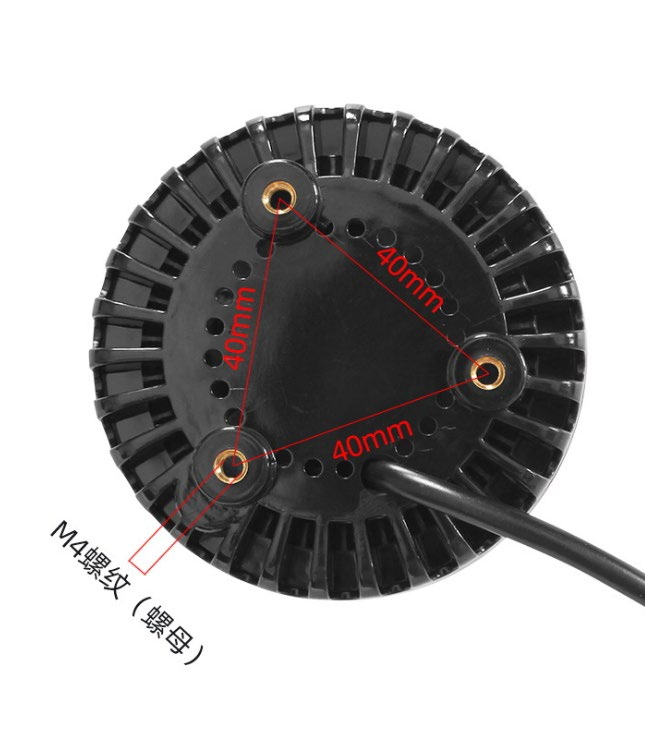
(1) , Screw style
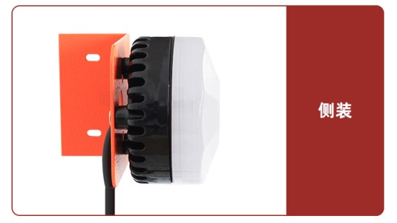
(2) , Magnetic suction payment
7, Simple functional testing and PC End debugging instructions
After the user receives our serial port controlled product, Simple functional testing can be conducted according to the instructions, To avoid the trouble of disassembly and assembly in the later stage
Facilitate troubleshooting in case of future issues; (The software used for testing sscom5.13.1 Serial port debugging software, Need to consult customer service)
RS485 The test we used is as shown in the picture USB Turn 485 Modules are used to connect computers for simplicity
Single testing and explanation; (Note Turn: USB Modules are not included as gifts with the goods 485 If needed, please purchase separately, Testing)
Step 1: Install our alarm system
Cable 485 Generally default yellow line (Green line A+/Connect separately B-) To the module
Two terminals AB Then plug the module into the computer, Interface connection to computer USB-A Interface connection to computer;
Step two: Install serial port driver, Can be downloaded by oneself (Baidu search CH340G Drive) ; it's fine too
Contact our customer service, We can provide it for free sscom5.13.1 Serial port debugging software and driver programs;
(If using others 485 Communication module, Drivers may vary, Please take what you have in hand 485 Install suitable drivers based on communication equipment)
Step three: Software testing; Connect the power amplifier board to be tested USB Turn 485 The module is plugged into the computer USB-A, Of course
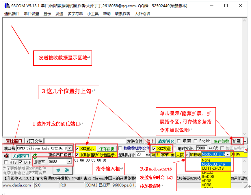
Double click to open sscom5.13.1, Operate as shown in the diagram:
1, Click on the communication port and select the corresponding port, After installing the driver, plug in our device, Under normal circumstances, there would be one life The name is USB-SERIAL CH340 The port, If not, the second step of installing the driver may not have been successful (If used
Using others 485 Communication module, The naming of port numbers may vary, Please refer to actual use; )
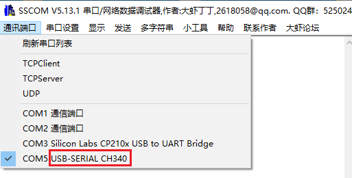
Please refer to the software operation page and functions below sscom5.13.1 Page functional diagram (Generally, there is no need to set it separately) :
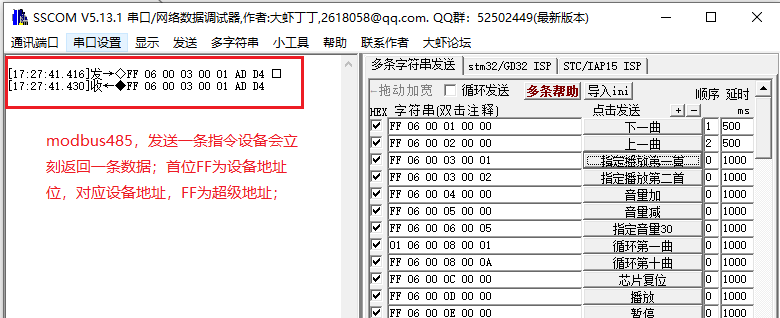
2, After selecting the correct port, Click to open the serial port, Then supply power to the amplifier board, Feel free to post Send the following command:, If the device is connected normally, This
It will immediately return a piece of data; The device that sends control instructions will immediately return the same instruction upon receiving it, indicating the string
The oral connection is normal;
3, After the above operation is correct, Can be referencedInstruction tableTest the functionality of the power amplifier board by sending instructions through software, Control the playback of voice and
Flashing police lights, etc;
8, common problem
The command sent after power supply did not play;
If there is no playback triggered after power supply, First, observe the status of the amplifier board indicator light;
1, The indicator light is not on: Indicates that the power amplifier board is not currently in operation, Please check if the power supply is normal;
2, The indicator light stays on constantly.: If the playback command indicator light is still on when sending the playback command, One possibility is that the power amplifier board did not detect speech Documents (Lost or damaged voice files, Or the voice file device replaced by the user cannot recognize it) , Can be connected using a data cable Computer inspection, Details for reference5.1; The second possibility is that the serial port did not connect successfully, Can the trigger port on the board be triggered to see if it works Play, If possible, please check if the serial port connection is normal, Is the computer serial port driver installed successfully, Specific referencePrevious chapter;
3, The indicator light is flashing: Indicate that the device is currently in playback mode, If no sound is heard, Please check if the voice file matches our requirements Requirements for explanation;
θ The voice playback tone is abnormal, When the volume is increased, the sound becomes intermittent;
The reason for this situation may be that the power supply voltage is too low or the output power of the power supply is insufficient, Please check the power of the power supply Voltage and output power, Our amplifier board requires at least DC12V The above voltage, Output current 1~2A about, Connect 4 Europe or 8 European horn, To ensure normal operation; Unable to play after changing one's own voice file;
The voice file needs to be MP3 Format, The recommended bit rate is not higher than 192kbps,And it must be a sampling rate supported by the product, Not supporting production Sampling rate of products MP3 The file format may not play, Details for reference5.1;
θ The played voice does not correspond to the sent command;
1, Our product plays in chronological order of voice file replacement, Not in file name order;
2, Perhaps the original voice was not deleted completely, There are hidden files present, You can format the memory first and then convert the voice file as needed Copy the required order one by one into it;
There is no response when connecting to the computer;
Please check if the cable used supports data transmission function, Suggest using our gift Micro USB data cable;


Leave a Reply