
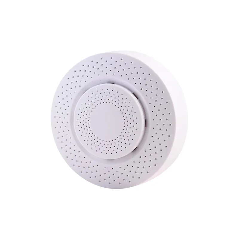
Air temperature and humidity sensoruseinstructions
1, summary
Internal configuration of air temperature and humidity sensorMEMSSpecialized modules are used to measure air temperature and humidity, Good linearity, High stability. StandardMODBUS-RTUCommunication protocol, RS485Digital signal output, Suitable for long-distance network transmission. Fully compatible with various upper computer configuration software such as Kingview, Easy to match with third-party devices. Can be widely used in meteorological stations, Greenhouse, Smart aquaculture, Factory, commercial buildings, and IoT environmental monitoring field.
2, Main technical indicators
| DC power supply | DC9-24V | |
| Work environment | -20~50Degree, 15~90%RHNo condensation | |
| Transmission distance | 500Rice (RS485Communication specific cables) | |
| Measurement range | Air temperature | Range: -40~80℃Accuracy: ±0.5℃ |
| Air humidity | Range: 0-100%RH Accuracy: ±3%RH | |
| Output signal | RS485Output | |
3, Installation and debugging
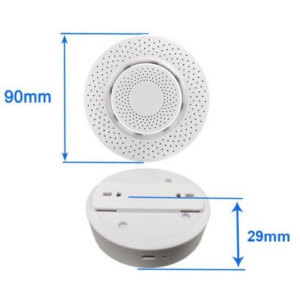
3.1External dimensions90*25
3.2Wiring instructions
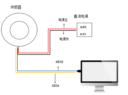
Cable definition: ①red thread: DC9-24VPower Supply+
②Black line: Power supply ground (GND)
③Yellow line: RS485-A
④Blue line: RS485-B
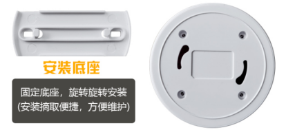
3.3Installation method
3.4Address setting (It has been set up at the factory, See detailsSensorsNameplate, If modifications are required, follow the instructions below)
The sensor address is selected by the dip switch, Users need to be present001~255Select and set the slave address internally, After setting, power off and restart are effective.
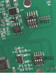
The four digit dip switch for dip code 1 as shown in the above figure1, 2, 3, 4Representing numerical values1, 2, 4, 8, Four digit dip switch for dip code 21, 2, 3, 4Representing numerical values16, 32, 64, 128, dial to“ON”Is a valid value, Dial to“ON”The opposite direction is an invalid value, The address is the numerical value obtained by adding valid values. Example:: The address is100, Then dial the code switch3, 6, 7Position dialed toONLocation, That is4+32+64=100.
3.5Sensor debugging
(1) UseUSBTurn485Connect the computer with a cable
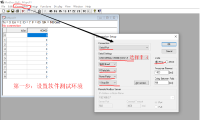
(2) Open on the computermodbus pollSoftware, Then configure the software basic parameters according to Figure 1, Select after configuration is completeOKJust enough.
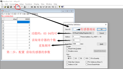
(3) Configure the environmental parameters for obtaining sensors, Set according to Figure 2, The sensor address is based on the address on the nameplate on the back of the corresponding sensor; The number of registers can be set according to requirements; After setting up, clickOKCan communicate with the sensor normally.
(4) If you want to obtain instructions for issuing and returning, Click in sequence as shown in Figure 3①②Just enough.
3.6Communication protocol
Output method: RS485
Communication protocol: MODBUS RTU
Baud rate: 9600
Data bits: 8Position
Checksum: NONE
Stop position: 1Position
Protocol specifications:
| Address code | Function code | data Sum verification | Numerical value | ||
| Or | 1~255 | 03data Verify status04 | Verify high position | Byte | Communication protocol reference |
| Protocol standards | 1 | 1 | n | 1 | 1 |
The positions of various parameter registers and sampled values are kept in decimal places as followsMODBUS-RTURegister address, Parameters.
| Air temperature | 0000H | 0001H |
| Air humidity | Company | Range |
| Sampling value | ℃ | %RH |
| Operation | -40~80 | 0~100 |
| read-only | /10 | /10 |
| Operation | read-only | Read only |
Protocol analysis:
①Inquiry instruction: 01 03 00 00 00 02 C4 0B
01Sensor address;
03Function code;
00 00Read the starting position of the register;
00 02Read the number of registers;
C4 0BVerification
②Return instruction: 01 03 04 01 07 01 D7 0B C0
01Sensor address;
03Function code;
04Data length;
01 07 Air temperature 01 07 (hexadecimal) That is26.3℃
01 D7 Air humidity 01 D7 (hexadecimal) That is47.1%RH
0B C0Verification
4, matters needing attention
※ Be careful not to connect the sensor cable incorrectly, Otherwise, it may burn out internal components.
※ Sensors485Do not plug or unplug wires with power on, Otherwise, it may cause damage485Communication chip.
※ Please try to use signal specific cables to increase transmission distance.
※ SensorsRS485The station address setting shall not be duplicated with other slave station addresses.
※ Our company refers to the communication protocol when the product leaves the factoryMODBUS-RTUProtocol standards, Our company can provide specific communication protocol formats, Convenient for users to master (See detailsMODBUS-RTUProtocol manual) .
※ SensorsRS485signal communication, Note that the maximum number of secondary stations should not exceed31One, Otherwise, it needs to be added separatelyRS485Bus bridge (Relay) , And with the main stationMODBUS-RTUagreement, The baud rate and other data formats must be consistent.
※ Large scale customers, Our company can develop programs according to the user communication protocol.
※ The default data format when the product leaves the factory1, 8, 1, 9600, N (1Starting position, 8Number of digits, 1Stop position, No verification, 9600bpsBaud rate) . If the user needs to modify the baud rate or data format, Please notify in advance when placing an order.
5, Common problems and solutions
The device cannot connect to the computer orPLCPossible reasons:
1, There are multiple computersCOMmouth, The selected serial port is incorrect.
2, Equipment address error, Or devices with duplicate addresses, Check if the sensor address is set correctly, If necessary, use a multimeter to measure the status of the dip switch.
3, Baud rate, Verification method, Data bits, Stop position error.
4, The host polling interval and waiting time for response are too short, Suggest setting it in1000msabove.
5, 485The bus is disconnected, OrA, BReverse wire connection.
6, Too many devices or too long wiring, Power should be supplied locally, Add485Enhancer, Simultaneously increase120European terminal resistor.
7, RS485Single end grounding of bus communication cable shielding layer, Suggest grounding on the main station side.
8, USBTurn485Driver not installed or damaged.
9, Equipment damage.


Leave a Reply