
Radar flowmeter parameters
▲ Speed measurement range: 0.1-20m/s;
Speed measurement accuracy: ± 0.01m/s; ±1%FS;
Speed measurement frequency: 24GHz;
Speed measurement elevation angle: 30-70 °;
Speed measurement beam angle: 12 °;
Maximum measuring range: 100m;
Power supply: DC6-30V;
Average power consumption: operating current<40mA, standby current<5mA (@ DC12V);
Protection level: ≥ IP65;
Operating temperature: -40 ℃ to+80 ℃;
Digital interface: RS232/RS485 interface; Modbus protocol;
Installation and Debugging Plan and Operation and Maintenance Plan
I. Installation and Debugging of Speed Radar Probe
1.InstallationDiagram
The installation diagram of this product is as follows. When the radar wave shines on the water surface, the illuminated area is similar to an ellipse.
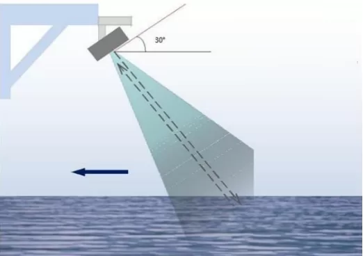
The appropriate installation angle should be selected to ensure that the illumination range is on a stable water flow surface. Accurately understanding the irradiation range of radar waves helps to choose the appropriate installation location and avoid some easily disturbed scenes, such as tree branches swaying in the wind on both sides of a river.
2. Installation Point Selection
The selection of flow measurement channels is directly related to the accuracy of flow measurement. In order to obtain better flow measurement results, the flow measurement channels should meet the following conditions as much as possible:
(1) There are no huge stones blocking the water flow in the measuring section, and there are no phenomena such as huge eddies or turbulence.
(2) The flow measurement section should be smooth, stable, and have concentrated water flow.
(3) The flow measurement section should be kept smooth to prevent the accumulation of floating objects.
(4) The flow measurement section should be in a natural flowing state, with no dams built downstream nearby.
(5) There are no weeds, branches, or other interfering objects that can shake within the beam angle range of the flow meter at the measuring point.
3. Installation height selection
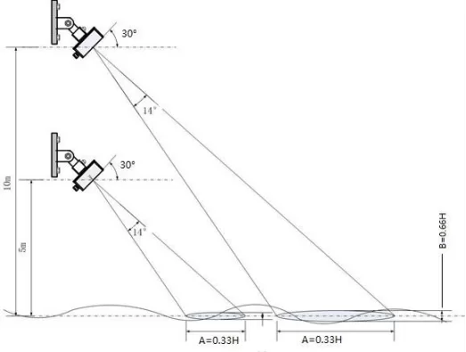
Choose the appropriate installation height based on the scene. The installation height selection must meet the following requirements:
(1) The beam range of the current meter should be fully illuminated on the water surface as much as possible.
(2) The flow velocity echo signal in areas with relatively calm water surface will be weaker. In such scenarios, the installation height should be minimized as much as possible to improve the equipment's echo acquisition capability.
(3) The boundary of the radar illuminated water surface area is directly proportional to the installation height. When the current meter beam illuminates the water surface, the A and B parameter values (actual installation height in meters) multiplied by the following values are the actual corresponding parameters.
Beam width of flowmeter (longitudinal) A=H * (tan (30+7))o-tan(30-7)o)=0.329H
Beam width of flowmeter (transverse) B=2 * H * tan16o/cos30o=0.662H
4, Installation steps
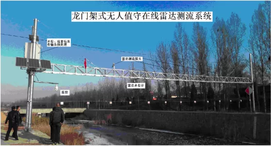
Non contact radar flow measurement system uses a non-contact radar speed probe for flow velocity measurement, which is not affected by water bodies. The installation method is mainly vertical pole type, that is, constructing a reinforced concrete foundation on the shore, and then constructing the main pole of the vertical pole. A cantilever is installed at the corresponding position on the upper part of the main pole, and the speed probe is installed at the end where the cantilever extends. Before installing the equipment, confirm whether the installation foundation and cantilever orientation meet the installation requirements. Install the solar panel at the corresponding position on the top platform of the bracket and fix it.
(1) Before installing the equipment, confirm whether the installation foundation and cantilever orientation meet the installation requirements. Install the solar panel at the corresponding position on the top platform of the bracket and fix it.
(2) Solar panels, batteries, charging controllers, and other equipment are installed in the solar control box and the chassis is fixed on the bracket.
(3) The speed probe is installed at the front end of the cross arm of the bracket and fixed with a dedicated fixing device.
(4) The cross arm is installed at the corresponding position of the bracket, clamped with screws, and tightened with steel wire to prevent it from swinging up, down, left, and right.
(5) The positive and negative terminals of the battery should be taped together to prevent short circuits caused by metal objects hitting them. Test battery voltage and solar panel current and voltage.
(6) Connect the probe cable and solar panel cable into the chassis along the perforated line reserved on the bracket for equipment debugging.
(7) After the device is powered on, open the data collector for parameter settings, including station number, system number, central station address, time settings, etc.
(8) After installation, multiple sets of manual flow rate data tests will be conducted to observe whether the real-time data display is normal on site, and verified at the central station until the calibration data is obtained.
(9) After debugging, initialize the radar speed probe; After installation and debugging, make on-site installation and debugging records and take photos.
2, Installation and debugging of telemetry terminal
1. Installation specifications
(1) The telemetry terminal should follow the principles of saving cables and being easy to operate. At the same time, it should be installed in a place with good transmission signal quality, as far away as possible from electromagnetic interference sources, no dripping water, and no strong vibration.
(2) When installing telemetry terminals, the chassis should have good grounding, with a grounding resistance of ≤ 5 Ω and a grounding wire with a cross-sectional area of ≥ 4mm2Yellow green dual color copper core wire, both ends of the grounding wire should be fixed with bolts.
(3) The telemetry terminal should ensure that wiring is carried out in the event of a power outage.
2.Installation steps
(1) Determine the installation location of the telemetry terminal according to the installation requirements.
(2) Fixed telemetry terminal. Fix the telemetry terminal on the wall or prefabricated cement pier or pole with expansion screws at the selected installation position.
(3) Connect the grounding wire. Connect the grounding bolt of the telemetry terminal box to the grounding electrode of the ground grid with a grounding wire. The grounding wire should be protected with galvanized steel pipe. For outdoor areas, the protective pipe should be buried 20cm below the ground, and for indoor areas, it should be led along the wall to the telemetry terminal.
(4) Wiring of telemetry terminal. Connect the wires according to the equipment manual while ensuring that the telemetry terminal is powered off.
III. Installation Rendering
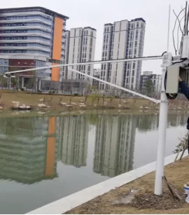
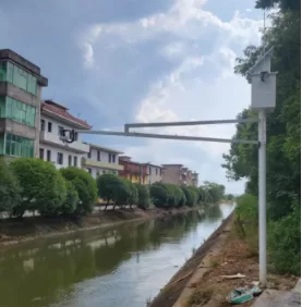
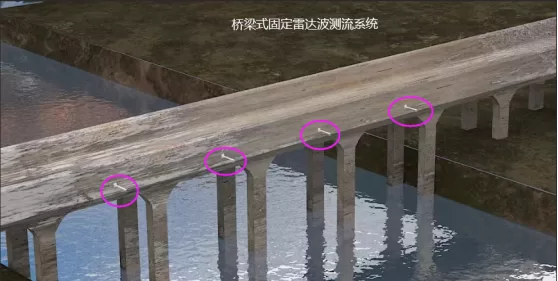
Cantilever Fixed Radar Wave Current Measurement System
IV. Instrument Debugging
(1) To connect through RS-485, the following adjustments need to be made
Baud Rate 9600
Data Bit 8
Parity None
End Bit 1
Flow Control None
1) Whether using RQCommander or other terminal software to set parameters, the two wires of the RS-485 interface need to be connected to the computer.
2) Generally, computers are not equipped with RS-485 interfaces and require an adapter
3) If there is a free USB port on the computer, use an RS-485 to USB cable to connect.
(3) Parameter settings before measurement
1) Computer installation software and USB serial port cable driver.
2) Connect the probe, click to open the software, and enter the interface.
Preliminary judgment:
Check the platform data to roughly determine whether it is an RTU problem or an instrument problem. For example, if the flow rate column on the platform is blank and the header is missing, the most likely reason is that the RTU has not been set to collect flow rates; The data collected by the platform is abnormal for a long time, which can be used to determine instrument or on-site environmental problems;
Prepare:
laptop, serial cable, direct test cable, multimeter, adjustable wrench, Phillips screwdriver, Phillips screwdriver, handheld radar speed gun, etc. before departure;
On site preparation:
Unscrew the connector of the instrument on the wireless system, connect our customized connection cable, and connect the serial port cable to the computer.
4. Common troubleshooting and handling
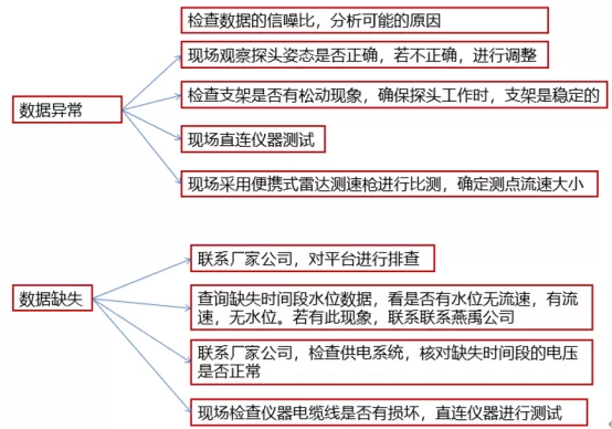
If you encounter faults such as no data or abnormal data at the site, you can gradually troubleshoot and solve the problem from the following aspects.
(1) Check the platform to see if the server has not received the data. If the data is received, ask the manufacturer's engineer to connect it to the platform;
(2) The server did not receive the data, and it was confirmed that the data transmission was normal, the server was normal, and the RTU was normal. This situation needs to be investigated on site;
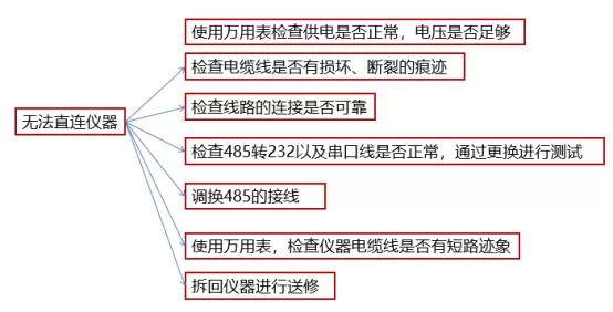
(3) On site investigation: Firstly, determine whether the equipment power supply is normal, and then perform connection testing on the computer according to the instrument operation instructions to determine whether the instrument is faulty (the instrument failure rate is very low);
(4) Check whether the RTU wiring is incorrect, whether the 485 to 232 module is faulty, and whether the RTU configuration is incorrect; If the water surface is affected by wind, the flow velocity on the downwind surface will be faster, while the flow velocity on the upwind surface will be slower, and even negative flow velocity may occur;
(5) If the water surface is affected by wind, the flow velocity on the downwind surface will be faster, while the flow velocity on the upwind surface will be slower, and even negative flow velocity may occur;
(6) The water surface is too calm to measure the frequency shift of radar waves;
(7) The instrument rotates and the probe orientation changes. When moving the bracket or extension arm, make a mark first and take a photo of the instrument posture; If there are tree leaves swaying within the radar wave range, it will cause data disorder.
(8) If there are tree leaves swaying within the radar wave range, it will cause data disorder.
V.Specific fault manifestations and troubleshooting methods
VI. Operation and maintenance
1. Flow meter maintenance
The sensor is the core component of the equipment, and special attention should be paid:
(1) Avoid wiping the surface of the sensor with a damp cloth, and gently wipe off the dust with a dry cotton cloth;
(2) Regularly check the status of the sensor, including whether the sensor electrodes have scratches, oxidation, damage, etc; When installing sensors, follow the operation manual in the instruction manual.
(3) When installing sensors, one should follow the operation manual in the instruction manual.
2. RTU maintenance
(1) Check if the telemetry terminal unit (RTU) is working properly, and if data storage, control, and transmission are normal; The power supply part should be checked first. After it is normal, the data collected by the telemetry terminal should be checked to see if it is normal. If the collected data is not fully transmitted, it may be due to loose plugs on the telemetry terminal. If the test returns to normal after unplugging and tightening, it is a problem with the data collector. If there is a situation where data cannot be received, the device should be checked. During the inspection process, it is found that the red light of the telemetry terminal's main module is on and there is a system crash problem. This is likely the reason for the inability to collect data normally. You can take a power-off and power on again, reset the system module, and reset the parameters. At this time, normal operation can be restored.
(2) Check if the data transmission module is working properly;
(3) Check if the power supply module is working properly: unplug the charging plug of the corresponding solar charging module, and unplug the bottom battery plug in the telemetry terminal. Then use the DC range of the digital multimeter to check the battery current and voltage. When the voltage is much lower than the lowest DC voltage range of the collector, modulator, and SMS communication terminal in the automatic measurement and reporting system, it is necessary to check the solar cell and its charging module. Unplug the input plug of the solar charging module. If the output voltage of the solar battery is within the normal range measured by the multimeter, plug in the input plug and measure again. If the DC voltage at this time is 0V, It is necessary to replace the charging module with a new one, and then measure it again. If the output voltage meets the required range, the maintenance strategy is to replace the new maintenance free battery, plug in the input plug of the battery and the charging module plug of the solar energy, and reset the accurate parameters. After that, simulate the transmission test and acquisition test of the communication terminal. If the central station can receive accurate telemetry data, it means that the fault of the flow equipment has been eliminated and normal operation has been restored.
(4) Check if the connecting wires of the entire system are loose or detached, if there is biological corrosion, unplug the charging plug and use a tool to tighten the screws, then connect the battery plug, reset the parameters, and conduct disassembly and communication terminal test simulation. If the central station can receive accurate telemetry data, it indicates that the flow equipment has resumed normal function.
Lightning Protection Measures Plan
1. Overall Plan
1. Lightning Protection Design and Planning
When designing hydrological equipment, lightning protection factors should be fully considered to ensure that the equipment meets lightning protection safety standards.
For important hydrological equipment, it is recommended to carry out specialized lightning protection design, including measures for direct and induced lightning protection.
2. Lightning protection measures for on-site equipment
The on-site equipment must be reliably grounded to ensure that lightning current can safely enter the ground and avoid damage to the equipment.
It is recommended that the diameter of the cable be at least 10mm to ensure its thermal stability and prevent melting due to excessive lightning current.
3. Grounding system
Ensure the reliability and effectiveness of the grounding device, regularly check the grounding resistance value, and ensure that it meets lightning protection requirements. All equipment and facilities should be properly grounded. In addition to using natural grounding devices such as support foundations, there should also be specially laid grounding devices. The total grounding resistance value can refer to the experience of the power department and building lightning protection, and is tentatively set at 10 ohms at the power frequency, which has been determined through testing.
All equipment and facilities should be properly grounded, in addition to natural grounding using support foundations and other parts, there should also be specially laid grounding devices.
The total grounding resistance value can refer to the experience of the power department and building lightning protection, and is tentatively set at 10 ohms at the power frequency, which has been determined through testing.
4. Evacuation Protection and Pre planning
Before a thunderstorm approaches, try to turn off relevant equipment, cut off power, unplug cable heads, and take evasive protection measures. When choosing a new hydrological station address, factors related to lightning strikes should be considered, and areas with frequent lightning strikes should be avoided as much as possible to reduce the pressure on future lightning protection work.
When choosing a new hydrological station location, factors related to lightning strikes should be considered, and areas with frequent lightning strikes should be avoided as much as possible to reduce the pressure on future lightning protection work.
5, Regular Inspection and Maintenance
Regularly inspect and maintain the lightning protection facilities of hydrological equipment to ensure that they are in good condition. For the problems and hidden dangers discovered, they should be repaired and dealt with in a timely manner to avoid lightning accidents.
For the problems and hidden dangers discovered, they should be repaired and dealt with in a timely manner to avoid lightning accidents.
6. Personnel Training and Awareness Enhancement
Strengthen lightning protection training for hydrological equipment operators and managers to enhance their lightning protection awareness and skill level. Regularly organize lightning protection drills and emergency drills to improve the ability and level of responding to lightning accidents. By implementing the above measures, the lightning protection capability and safety of hydrological equipment can be effectively improved, ensuring the normal operation of the equipment and accurate data collection.
Regularly organize lightning protection drills and emergency drills to improve the ability and level of responding to lightning accidents.
By implementing the above measures, the lightning protection capability and safety of hydrological equipment can be effectively improved, ensuring the normal operation of the equipment and accurate data collection.
2. Specific Plan
I. Overview
Hydrological facilities and equipment such as online ADCP flow measurement system, ultrasonic time difference flowmeter, and sediment testing equipment involve the application of power, communication, and electronic technology. After years of use, it has been found that this instrument is susceptible to lightning strikes. The damage caused by lightning strikes to hydrological measurement facilities can be divided into two types: direct lightning strikes and induced lightning strikes.
The damage caused by lightning strikes to hydrological testing facilities can be divided into two types: direct lightning strikes and induced lightning strikes.
Lightning protection grounding is divided into two concepts: one is lightning protection, which prevents damage caused by lightning strikes; The second is electrostatic grounding to prevent the harm caused by static electricity. With the increasingly widespread application of cathodic protection in storage tanks, its protection effect has received more and more attention, and the contradiction between lightning protection grounding standards and cathodic protection standards has become more and more prominent.
After preliminary research and discussion, it has been preliminarily determined that hydrological facilities and equipment are more likely to be affected by induced lightning strikes. Therefore, when formulating lightning protection plans, the main focus is on induced lightning strikes.
The damage channels of induced lightning strikes to hydrological measurement and reporting instruments and equipment are multifaceted, including signal channels, power supply channels, ground potential rebound channels, ground current rebound channels, and high-level impact channels at lightning strike points. Lightning protection must adopt a comprehensive lightning protection system that includes comprehensive prevention and control, overall prevention, multiple protections, and layer by layer defenses. The system uses methods such as induction, discharge, dissipation, prevention, and avoidance to dissipate, conduct, or suppress lightning on all channels of hydrological measurement and reporting facilities and equipment that are susceptible to lightning, in order to protect the safety of hydrological measurement and reporting equipment.
II. Lightning Protection Measures
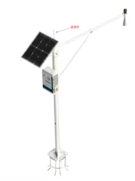
1. Apply advanced lightning protection equipment, such as lightning protectors, lightning rods, etc., to attract and disperse lightning energy, and reduce the damage caused by lightning to electrical equipment. See Figure 1 for example.
Example 1: Installing a vertical pole and installing a lightning rod
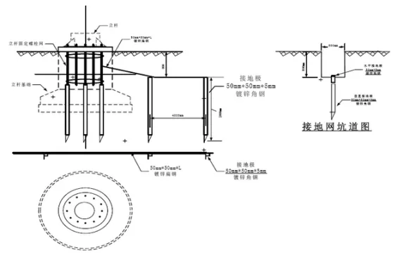
2. Establishing a good grounding system to ensure the safe operation of equipment and systems. And the grounding system should be connected to the groundwater layer or buried underground with high humidity to maintain the stability and reliability of the grounding resistance. See Figure 2 for an example.
Example Figure 2 Lightning Protection Grounding Network Design
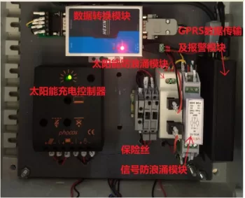
3. Surge protection module for integrated signals and power supply within the acquisition and control system. The anti surge module separates power and signal, effectively protecting terminal safety. See Figure 3 for example.
Example Figure 3 Internal Integration of Acquisition System
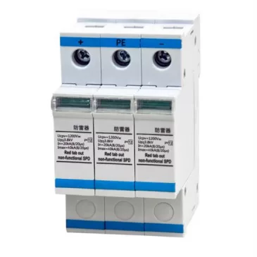
4) Connecting the solar power supply to a lightning arrester effectively shields against the risk of solar induced lightning. Refer to Figure 4.
Figure 4 Lightning arrester
5) Detection and regular maintenance of lightning protection devices. If any problems are found, they should be repaired or replaced in a timely manner.
6) Ensure the protection of lightning protection grounding wires. Lightning protection grounding wires are an important part of connecting equipment and grounding systems, and should avoid contact with other metal pipelines, cables, etc. to prevent corrosion or damage to the grounding wires.
7) Take lightning protection and shielding measures to avoid damage caused by lightning current passing through equipment and acquisition control systems. Common shielding measures include using metal shielding covers or installing metal shielding layers in cables. See Figure 5 for example.
Example Figure 5: Installing Cable Lines with Shielded Connection to Ground Grid
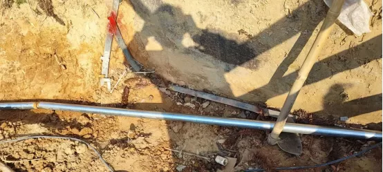
8) Equipment and acquisition control systems should be avoided and kept away from minefield locations as much as possible, and appropriate equipment should be selected for installation.
9) Strengthen the training of technical personnel on lightning knowledge and the promotion of protective measures, raise awareness of protection, and ensure the safety of workers.
10) The acquisition and control system should undergo regular preventive maintenance, check the reliability and normal operation of electrical equipment and systems, and prevent lightning accidents from occurring.
Reference
1. "Code for Design of Lightning Protection of Buildings"
2. "Management Measures for Professional Design and Construction Qualification of Lightning Protection Engineering"
3. "Lightning Electromagnetic Pulse Protection" IEC standard
4. "Technical Specification for Lightning Protection of Building Electronic Information Systems"
5. "Application of Lightning Protection Technology in Hydrological Measurement and Flood Reporting of the Yangtze River"


Leave a Reply