
Technical Requirements
Evaporation Measurement:
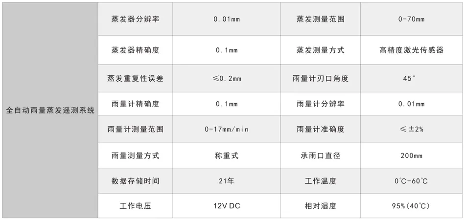
▲ Resolution: 0.1mm;
Measurement Range: 0-70mm;
Accuracy: 0.1mm;
Measurement Method: High precision laser sensor;
repeatability error: ≤ 0.2mm;
rainfall measurement:
measurement method: weighing formula;
Blade angle: 45 °;
Accuracy: 0.1mm;
▲ Resolution: 0.1mm;
Measurement range: 0-17mm/min;
Accuracy: ≤± 2%;
Technical Parameters
Software Interface
I. Equipment Overview and Principle
The fully automatic rainfall evaporation telemetry system can automatically measure evaporation and precipitation, automatically add/draw water, and automatically send measurement data to the central station server software platform through wireless network according to the requirements of documents such as "Water Surface Evaporation Observation Specification", "Precipitation Observation Specification", "Technical Specification for Hydrological Automatic Monitoring and Reporting System", "Hydrological Information Forecasting Specification", "Water Information Coding Requirements", etc., achieving automation of evaporation and precipitation observation.
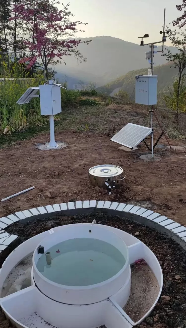
The fully automatic rainfall evaporation system consists of five parts: control box, weighing rainfall, automatic water replenishment overflow system, laser evaporation, and control software. The structure is shown in the following figure:
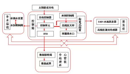
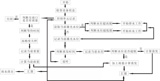
The fully automatic rainfall evaporation system is based on the traditional E601 evaporating dish and is connected to the E601 through a laser measuring dish by a control unit in the control box and a connector. The laser measuring dish is placed on the E601 evaporating dish, and a float is placed inside the measuring dish. When the water level of the E601 evaporating dish changes, the laser measuring dish will measure the water level of the E601 evaporating dish every hour and subtract the water level height of the previous measurement from the current reading to obtain the current evaporating height. The calculated evaporating value will also be recorded by the control unit and uploaded to the control software.
Weighing based rainfall mainly stores the current 5-minute rainfall. When the time is up, the weighing port control valve will automatically open to transport the stored rainfall to the high-precision weighing balance container for calculation. After the calculation result is sent to the control unit, the control valve under the high-precision weighing balance will open to discharge the rainfall in the container through the discharge port.
twoEquipment installation and debugging
Equipment installation
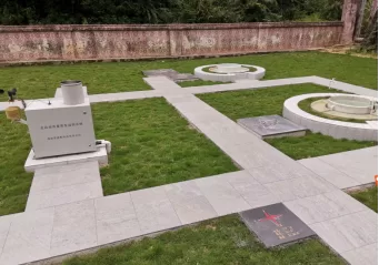
The installation of the equipment strictly follows the specific requirements for evaporator installation in SL 630-2013 "Water Surface Evaporation Observation Specification" for site layout and installation, while taking into account the rationality and aesthetics of the overall layout of the evaporation site (attached is the current situation map of the evaporation site). The specific specifications in SL 630-2013 "Water Surface Evaporation Observation Specification" are as follows:
(1) Selection of evaporation observation site:According to standard 2.1.2, the surroundings of the evaporation observation field should be open and flat to ensure smooth airflow; The size of the site in Article 2.2.1 of the standard should be determined based on the observation items and instruments of each station; The observation site should be flat and clean to avoid water accumulation; Grass or crops should be planted on the ground, with a height not exceeding 20cm. A fence with a height of about 1.2m should be set up around the area, and observation paths with a width of 0.3-0.5m should be laid in the field.
(2) Types of evaporation instruments:According to section 3.1.2 of the standard for self recording/remote sensing evaporators, an automatic measuring device or sensing device should be added to the evaporation bucket of a standard water surface evaporator.
(3) Installation of evaporation instrument:According to standard 3.3.1, the installation of water surface evaporators should meet the following requirements (as shown in the figure):
1. The evaporator mouth edge should be about 30cm above the ground, and the height difference of the evaporator mouth should be less than 0.2cm.
2. The water ring should be closely attached to the evaporator bucket, and the gap between the outer wall of the evaporator bucket and the inner wall of the water ring should be less than 0.5cm. The bottom of the drainage hole of the water ring and the bottom of the overflow hole of the evaporator bucket should be on the same water surface.
3. A 50cm wide (including the anti collapse wall) and 22.5cm high soil circle should be set between the water circle and the ground, and the anti collapse wall on the outer layer of the soil circle should be made of dry bricks. Leave an observation gap of no more than 40cm to the north of the soil circle. The measuring needle of the evaporator barrel should be located at the observation gap.
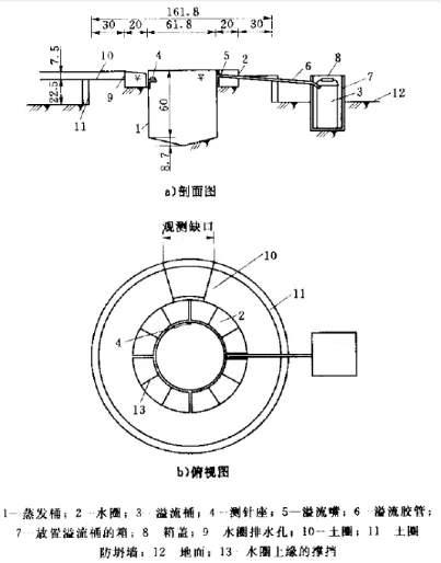
The layout and sealing of equipment connecting pipes should pay attention to the following requirements:
- The entire connecting pipe layout should be U-shaped, and it is strictly prohibited to embed a straight line in advance; The joint between the pagoda and the water pipe should be fixed with stainless steel clamps, and any looseness is strictly prohibited;
- The connection between the pagoda joint and the water pipe should be fixed with stainless steel clamps, and any looseness is strictly prohibited;
- After opening the E601 bucket, install the water pipe joint and seal it with waterproof measures to prevent water leakage and seepage;
- The solar energy layout should be placed in a place with good lighting conditions. When pouring the equipment box base, a conduit hole should be left in the middle to facilitate the connection of water pipes.
- When pouring the equipment box base, a wire hole should be left in the middle to facilitate the connection of water pipes.
Chassis Installation
- Place the chassis on the pouring base and use a level ruler to check if the chassis is installed horizontally. After ensuring that the chassis is level, fix it with M6-M8 expansion screws. The installation of solar energy must have a 45 ° angle, preferably facing in the direction of due south. The installation of E601 bucket must comply with hydrological regulations and must be horizontal. The power supply system is connected to the solar panel using a two core power cord. Thread the power cord out of the wiring hole of the installation tube, open the black plastic box under the solar panel, there are two terminal posts inside, and the right terminal post is connected to the red cable of the+pole and dual core wire; The terminal on the left is connected to a white cable with one pole and two core wires. When wiring, strip the two core cables by 20mm, fold them in half, and twist them into strands. Insert them into the two wiring holes of commonly used signaling components in the wiring socket, tighten them with screws, and finally fix the black plastic sealing box with screws and seal it with sealant.
- After ensuring that the chassis is level, fix it with M6-M8 expansion screws.
- The installation of solar energy must have a 45 ° angle, preferably facing in the direction of due south.
- The installation of E601 bucket must comply with hydrological regulations and the installation must be horizontal.
Power supply system connection
1.The solar panel is connected using a two core power cord. Thread the power cord out of the wiring hole of the installation tube, open the black plastic box under the solar panel, there are two terminal posts inside, and the right terminal post is connected to the red cable of the+pole and dual core wire; The terminal on the left is connected to a white cable with one pole and two core wires. When wiring, strip the two core cables by 20mm, fold them in half, and twist them into strands. Insert them into the two wiring holes of commonly used signaling components in the wiring socket, tighten them with screws, and finally fix the black plastic sealing box with screws and seal it with sealant.
2.Fix the solar panel bracket onto the solar panel using M6 bolts.
3.Fix the solar panel with connected wires and fixed brackets on the upright pole (if the solar panel is installed in the station building position, use screws to fix it)
4.Fix the charging controller on the installation base plate, and connect the solar cell, battery, and electrical unit (RTU) to the corresponding wiring terminals according to the instructions. Tighten the screws to avoid poor contact. Connect the battery to the charging controller, with the red wire connected to the positive pole and the black wire connected to the negative pole. After fixing the connection, place the battery in the equipment box.
5.Connect the battery to the charging controller, with the red wire connected to the positive pole and the black wire connected to the negative pole. After fixing the connection, place the battery into the equipment box.
RTU equipment box line connection
1. Connect the RTU power cable to the output terminal of the solar controller.
2. After checking and confirming that all types of cables are connected correctly, turn on the power switch of the equipment box and power up the equipment.
3. After the equipment is powered on and self checks normally, set the operating parameters of the RTU according to the requirements. After the parameter settings are completed, the testing work can be carried out.
After the parameter settings are completed, the testing work can be carried out.
Parameter Setting
The control box mainly includes the control unit, telemetry terminal unit (RTU), data transmission unit (DTU), power switch, etc.
- Control unit: used for equipment control, rainfall/evaporation calculation;
- Telemetry terminal: used for data acquisition and equipment control;
- DTU: Used for data transmission;
- Power switch: Power control.
Press the button switch on the RTU panel to light up the RTU LCD screen and display the main interface, as shown in the following figure:
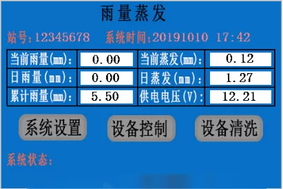
- Current Rainfall: displays the rainfall from 8am that day to the time of viewing;
- Daily Rainfall: Display the rainfall of the previous day when viewing;
- Accumulated rainfall: displays the total rainfall amount when the device is installed and viewed;
- Current evaporation: displays the evaporation amount from 8am to the time of viewing;
- Daily evaporation: Display the evaporation data of the previous day when viewed;
- Supply voltage: Display the current voltage of the battery.
System debugging
Local testing of the whole machine
During local testing of the whole machine, disconnect the connection line between the GPRS module and the RTU board, and directly plug it into the RTU with the local serial port cable. Use rainfall evaporation testing program for testing. Before testing, turn on the device, open the rainfall evaporation test serial port, and wait for the display screen on the RTU to enter the main interface to start. The interface of the rainfall evaporation test program is as follows:
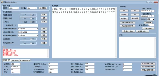
Rainfall evaporation test program
Scale data reading check:
Use the rainfall evaporation test program to read the scale data, which is completely consistent with the display on the digital weight transmitter.
Laser data reading inspection:
Use the rainfall evaporation test program to read the laser displacement sensor data, and compare it with the display on the laser displacement sensor. The error range is within 0.1mm.
Rainfall Test:
Use a measuring cup to take water larger than 0.1mm and pour it into the rain gauge. Wait for no more than 5 minutes to check the RTU display screen and see if the rainfall data on the screen is within 0.2mm of the measured data from the measuring cup. Pay attention to checking if there is any water leakage in the rainfall measurement process.
Evaporation Test:
Take an appropriate amount of water from the E601 bucket and weigh the water with a scale. Use the rainfall evaporation test program to calculate the corresponding depth of the water. Wait for 5 minutes and click the add test button of the rainfall evaporation test program. Compare the evaporation data on the day of adding the test with the calculated data, and the error range is within 0.1mm.
Pumping and Drainage Inspection:
Use the rainfall evaporation test program to control the pumping and drainage. Within 5 minutes after issuing the command, the equipment should carry out corresponding pumping and drainage, and check whether there is any leakage in the pumping and drainage.
Data storage and extraction check:
When the test lasts for more than 1 hour and the SD card has data, using the rainfall evaporation test program to extract the data should be able to correctly extract the corresponding data.
System acceptance
Functional acceptance. Confirm that the fully automatic rainfall evaporation telemetry system meets all the technical performance requirements of the equipment in this project.
Performance acceptance. Evaluate the performance of the fully automatic rainfall evaporation telemetry system, including measurement accuracy, stability, and reliability.
Training outline for fully automatic rainfall evaporation telemetry system
| Course Topic | Syllabus | Teaching hours (hours) |
| Fully automatic rainfall evaporation telemetry system | (1) Basic knowledge of fully automatic rainfall evaporation telemetry system: Introduce the characteristics, principles, and application scenarios of the equipment. | 1.5 |
| (2) Basic operation of the fully automatic rainfall evaporation telemetry system on site. | 2 | |
| (3) Basic functions and abnormal handling of the entire automatic rainfall evaporation telemetry system. | 2 | |
| (4) System maintenance and upkeep: Introduce how to properly maintain and upkeep the fully automatic rainfall evaporation telemetry system, including regular inspections, dust cleaning, component replacement, etc. | 4 | |
| (5) Course Summary and Q&A: Summarize the course content, answer students' questions, and provide corresponding operational guidance and suggestions. | 2 |
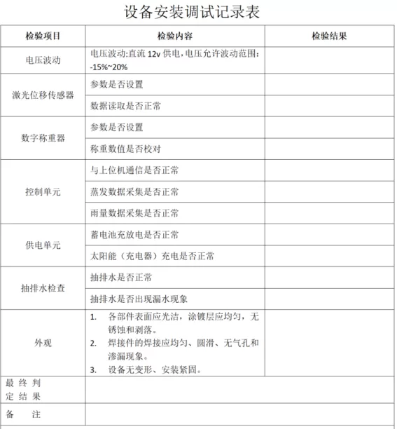
Automatic evaporation lightning protection scheme
Installation of lightning arrester
Installation method and requirements for power lightning arrester
The installation position of power lightning arrester is inside the automatic evaporation equipment chassis, and all external equipment must be installed with power lightning arrester.
The power surge arrester has three ports, namely power positive, power negative, and grounding; The positive and negative wires of the external equipment power cable must pass through the positive and negative ports of the power lightning arrester before being connected to the equipment. The length of the grounding port wiring should be ≤ 500mm. If it cannot meet the standard of ≤ 500mm due to limitations, it can be appropriately extended, but the principle of wiring should be followed as short as possible. The turning angle should be greater than 90 degrees (arc angle rather than right angle), and the grounding wire should be connected to the independent grounding grid.
Installation precautions:
When installing a power lightning arrester, the grounding system should be firmly connected before connecting other lines. During installation, the power must be disconnected and live operation is strictly prohibited; The connecting wires must meet the requirements.
The lightning arrester does not require special maintenance, it only needs to be regularly checked for loose connections and whether the working status indicator light is normal. When the working status indicator light turns green, it indicates that the lightning arrester is working properly. When it turns red, it indicates that the lightning arrester has damaged components and its lightning protection effect has deteriorated, and it must be replaced immediately.
When the working status indicator light turns green, it indicates that the lightning arrester is working properly. When it turns red, it indicates that the lightning arrester has damaged components and its lightning protection effect has deteriorated, and it must be replaced immediately.
Installation method of signal lightning arrester
The signal lightning arrester is installed inside the equipment chassis, and all external signal lines must be installed with signal lightning arrester.
The signal lightning arrester has three ports, namely signal A, signal B, and grounding; External equipment signal cables AB signal lines must pass through the signal lightning arrester AB port before being connected to the equipment. The grounding port wiring length should be ≤ 500mm. If the standard of ≤ 500mm cannot be met due to limitations, it can be appropriately extended, but the principle of wiring should be followed as short as possible. The turning angle should be greater than 90 degrees (arc angle rather than right angle), and the grounding wire should be connected to an independent grounding grid.


Leave a Reply