

1.8 QR Code Control and RTC Control
This section mainly introduces the common applications of QR code controls and RTC controls in the Modbus protocol. The QR code control only supports binding variables in [Tools - Protocols and Variables - Logic Processing]
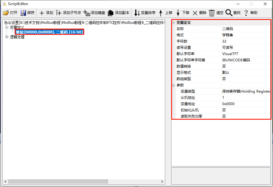
This section uses the screen as the master station and creates one save register for the application of QR Code Control, as shown below
Routine download link:"Modbus Tutorial 8 - QR Code Control and RTC Control V1.0"
For protocol activation and variable-related instructions, refer to the link: "Modbus Basic Parameter Description"
1.8.1 QR Code Control
The [QR Code] screen primarily provides an example of how to use the QR code control. The QR code control can display a set string in the form of a QR code, which can be recognized by some scanning devices.
Note: The basic series of serial port screens require special firmware support to use the QR Code Control
Screen/Logic Configuration
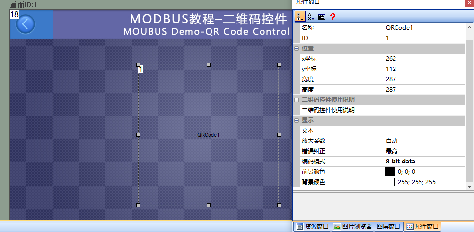
Add a QR Code Control (Control ID: 1) to the screen, and configure the control properties as follows:
Add a variable in the "Protocol and Variable Settings" section, with the variable type set to "String" and a string length of 32, as shown below
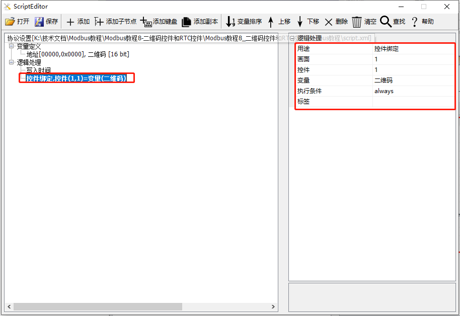
Add a logic processing in the "Protocol and Variable Settings" with the purpose of "Control Binding" and the screen set to "1"; the control is "1"; the variable is "QR Code", as shown below
Run Preview
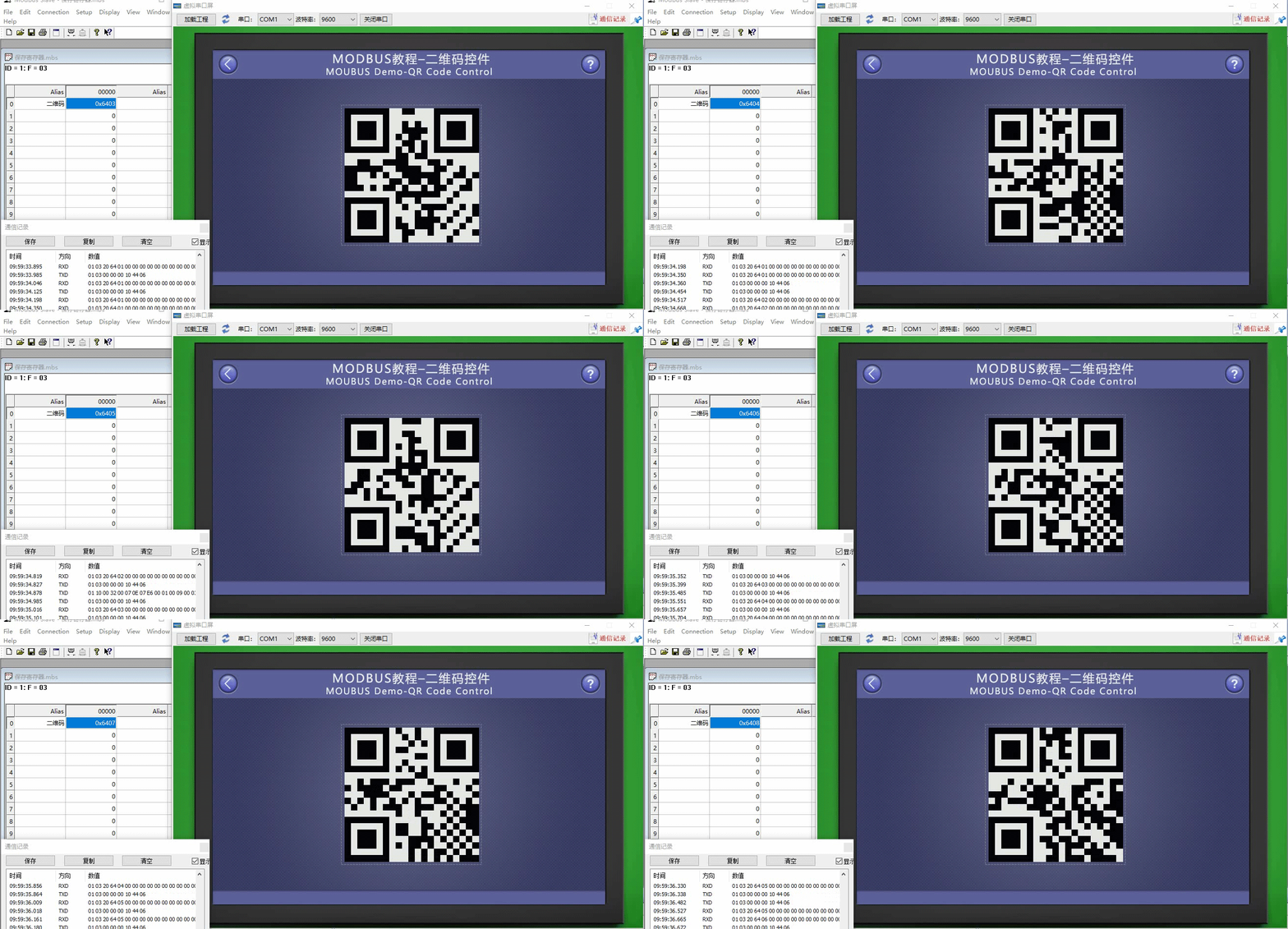
At this point, compile the project and run the virtual serial port screen. The QR code control displays the string "VisualTFT" in the form of a QR code. When connected to the Modbus Slave software, the QR code control displays the corresponding string.
1.8.2 RTC Control
The "RTC Control" screen mainly provides an example of how to use the RTC control. When the screen acts as the master, it modifies the RTC time of the slave; the slave creates a fixed address holding register to store time variables, with seven consecutive holding registers for year, month, week, day, hour, minute, and second. The screen periodically writes the latest time to the slave register through the 0x10 command
Screen/Logic Configuration
Add an RTC control (control ID: 1) to the screen as shown below:
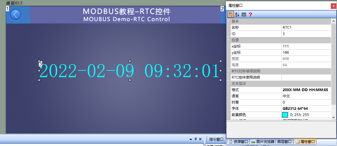
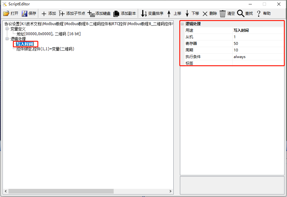
Add a logic processing in the "Protocol and Variable Settings" with the purpose of "Write Time"; the slave address is "1"; the register is "50" (decimal); the cycle is "10" (unit: seconds), as shown below:
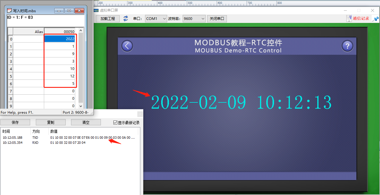
Run Preview
At this point, compile the project and run the virtual serial port screen. When connected to the Modbus Slave software, the master sends the RTC time to the slave every 10 seconds.


Leave a Reply