
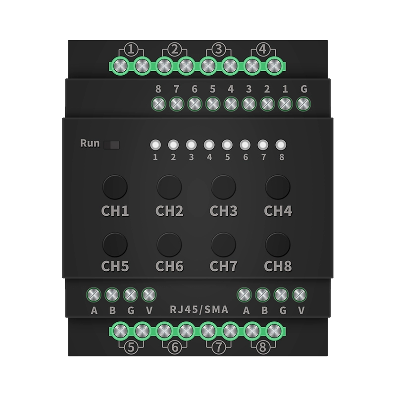
Version: V1.1
I. Product Introduction
W816 is aultra small intelligent programmable controllerdesigned specifically for smart homes, commercial lighting, and agricultural automation. No gateway required, supports 8 high-power relays (16A each), compatible with mobile apps, voice control, and scheduled tasks, making it an "all-in-one butler" for both home and business scenarios.
Purchase Product:https://www.modbus.cn/product/30890.html
II. Core Functions and Features
1. Hardware Advantages
- Ultra Small Size: Only occupying 4 empty slots, it can be easily installed in a home electrical box.
- High power load: Each circuit supports 16A resistive loads (such as lamps and sockets) and 8A inductive loads (such as motors).
- Industrial grade design: Operating at a wide temperature range of -20 ℃ to 80 ℃, suitable for complex environments.
2. Flexible Expansion
- Wire free Splicing: Installed on the same level guide rail, multiple modules can be directly spliced and expanded.
- Full protocol compatibilitySupports protocols such as Modbus, TCP/IP, MQTT, etc., providing seamless integration with smart home platforms.
- Wireless to wired conversionSupports WiFi/433M/315M to 485 bus, making old devices instantly intelligent.
3. Little white friendly
- Dial code to set addressNo software is required, simply toggle the switch to set the device ID (1-32).
- One-Key RecoveryIncorrect operation can restore factory settings and operate with zero threshold.
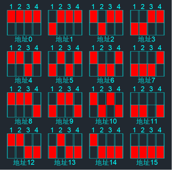
There is a 4-digit side dial switch on this module, and the default factory address is 0. The address can be set to 0-15, as shown in the following figure
3, Technical parameters
| project | Specifications |
|---|---|
| Working Voltage | DC 12V (customizable 12-24V) |
| load capacity | Resistive load ≤ 16A, inductive load ≤ 8A |
| Communication method | 485 bus (standard), RJ45 Ethernet port WiFi, 433M, GPRS |
| Number of input channels | 8-way optoelectronic isolation input (compatible with dry contacts) |
| ambient temperature | -20℃~80℃ |
| Size | 92.5mm × 76.2mm × 60.5mm |
4, Quick Start Guide
1. Installation and wiring
- Fixed moduleInsert the standard DN35 guide rail and ensure that the power is turned off.
- Connecting Load: Connect the lighting fixtures, curtain motors, etc. to the relay output terminals (OUT1~OUT8).
- Connect power supply: Use a 12V adapter to supply power (do not connect the positive and negative poles in reverse).
- Networking configuration:
- Wired:
Run indicator light status: The green light flashes when powered on and remains on, and it turns ice blue after successfully connecting to the server.
Rj45 indicator light status: After successfully connecting to the network, the green light stays on and the orange light flashes.
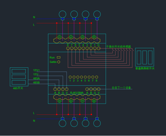
Wiring Topology Diagram
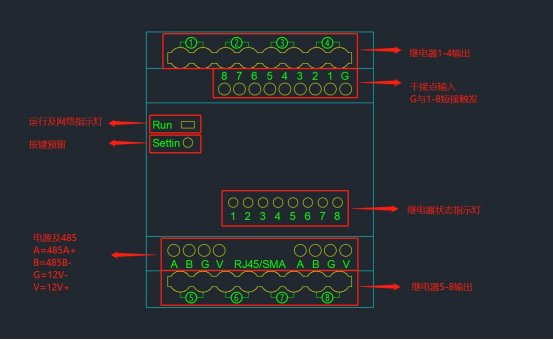
Interface Description:
1. V=12V Positive Input
2, G=12V negative input
3, A B=485 interface
4, ①②③④ ⑤⑥⑦⑧=8 relay outputs
5, RJ45/SMA=network communication
6, G 1 2 3 4 5 6 7 8=dry contact input (e.g. G and 1 connect to trigger the first relay)
7, RUN=running indicator light (green for unconnected TCP and ice blue for connected TCP)
5, protocol instruction explanation
private protocol
communication protocol description
protocol basic information
- 71]: 9600: 9600
- Default Address:
1A CA 27 87 00(Factory Test Default Address) - Universal Address:
AA AA AA AA AA(For Special Operations)
Protocol Format
The protocol data frame consists of the following parts:
- Address: 5 bytes, identifying the module address.
- Instruction Area: The length and content vary depending on the operation.
- checksum: fixed as
0F
Function Operation Instructions
1. Query Module Address
- Instruction Format:
5个字节地址 + 56 56 56 0F - Function: Query the current address of the module.
- Example:
1A CA 27 87 00 56 56 56 0F2. Modify Address
- Explanation: The first 4 bytes are fixed, and the 5th byte is changed through a dip switch.
- Example:
1A CA 27 87 XX (XX 为拨码设置的新地址)3. Querying Module Status
- Instruction Format:
5个字节地址 + 86 86 86 0F - Return Format:
5个字节地址 + 00 00 00 00 00 00 00 00 0F(8 switch states, 00 indicates closed, 01 indicates open) - Example:
  查询指令:1A CA 27 87 00 86 86 86 0F
  返回示例:1A CA 27 87 00 00 01 00 01 00 01 00 0F (假设开关状态为:关-开-关-开-关-开-关-开)
4. Restore factory settings
- Instruction Format:
5个字节地址 + 96 96 96 0F - Function: Erase K1-K8 storage area to restore default settings.
- Example:
1A CA 27 87 00 96 96 96 0F5. Force K1-K8 to jog mode
- Instruction format:
5个字节地址 + A6 A6 A6 0F - Explanation:
- Default is to long press for 5 seconds to automatically switch to flip mode.
- Before setting, it is necessary to restore the factory settings.
- Example:
1A CA 27 87 00 A6 A6 A6 0F6. Enable/Disable K1-K8 Input Data Storage Function
- Enable:
- Instruction Format:
5个字节地址 + 56 56 56 0F - LED Display: Blinks once and remains on.
- Close:
- Instruction Format:
5个字节地址 + 46 46 46 0F - LED indicates: Flashes twice and remains off.
- Example:
  开启:1A CA 27 87 00 56 56 56 0F
  关闭:1A CA 27 87 00 46 46 46 0F
7. K1-K8 On/Off Storage Instruction
- Instruction Format:
- Open a certain path:
地址 + XX XX XX XX XX ... XX(XX is a specific value) - Close a certain path:
地址 + XX XX XX XX XX ... XX(XX is a specific value) - Specific Instruction: Operation Open Instruction Value Close Instruction Value K1 On/Off
0010K2 On/Off2030K3 On/Off4050K4 On/Off6070K5 On/Off8090K6 On/OffA0B0K7 On/OffC0D0K8 On/OffE0F0 - Example:
  K1 开启:1A CA 27 87 00 00 XX XX XX XX XX 0F
  K1 关闭:1A CA 27 87 00 10 XX XX XX XX XX 0F
8. Single Channel Control
- Instruction Format:
- Flip:
地址 + 00 00 XX 02 0F(XX is the number of channels -1) - Only On:
地址 + 00 00 XX 01 0F(XX is the number of channels -1) - Only Off:
地址 + 00 00 XX 00 0F(XX is the number of channels -1) - Example:
	第一路翻转:1A CA 27 87 00 00 00 02 0F
	第一路只开:1A CA 27 87 00 00 00 01 0F
	第一路只关:1A CA 27 87 00 00 00 00 0F

	第二路翻转:1A CA 27 87 00 00 01 02 0F
	第二路只开:1A CA 27 87 00 00 01 01 0F
	第二路只关:1A CA 27 87 00 00 01 00 0F

	第三路翻转:1A CA 27 87 00 00 02 02 0F
	第三路只开:1A CA 27 87 00 00 02 01 0F
	第三路只关:1A CA 27 87 00 00 02 00 0F

	第四路翻转:1A CA 27 87 00 00 03 02 0F
	第四路只开:1A CA 27 87 00 00 03 01 0F
	第四路只关:1A CA 27 87 00 00 03 00 0F

	第五路翻转:1A CA 27 87 00 00 04 02 0F
	第五路只开:1A CA 27 87 00 00 04 01 0F
	第五路只关:1A CA 27 87 00 00 04 00 0F

	第六路翻转:1A CA 27 87 00 00 05 02 0F
	第六路只开:1A CA 27 87 00 00 05 01 0F
	第六路只关:1A CA 27 87 00 00 05 00 0F

	第七路翻转:1A CA 27 87 00 00 06 02 0F
	第七路只开:1A CA 27 87 00 00 06 01 0F
	第七路只关:1A CA 27 87 00 00 06 00 0F

	第八路翻转:1A CA 27 87 00 00 07 02 0F
	第八路只开:1A CA 27 87 00 00 07 01 0F
	第八路只关:1A CA 27 87 00 00 07 00 0F
9. Full circuit control
- Instruction format:
- 1-8 fully open:
地址 + 01 01 77 88 0F - 1-8 fully closed:
地址 + 01 02 77 88 0F - Example:
  1-8 路全开:1A CA 27 87 00 01 01 77 88 0F
  1-8 路全关:1A CA 27 87 00 01 02 77 88 0F
10. Universal fully open/fully closed
- Instruction format:
- Universal fully open:
通用地址 + 30 77 88 0F - Universal fully closed:
通用地址 + 30 77 88 0F - Example:
  通用全开:AA AA AA AA AA 30 77 88 0F
  通用全关:AA AA AA AA AA 30 77 88 0F
Internal protocol
1. Instruction Format
All instructions are 8 bytes, and the format is as follows:
[0x55][地址][功能码][数据1][数据2][数据3][数据4][校验和] - checksum=sum of the first 7 bytes and take the last two bits (such as
55+01+32+00+00+00+01=89).
Baud rate 9600, 8 data bits, 1 stop bit, no checksum.
Format of data frame sent by the upper computer:
| Data header | Address | Function code | Data area | Checksum | |||
| 1 bytes0x55 | 1 bytes | 1 bytes | The 1 bytes | The 2 bytes | The 3 bytes | The 4 bytes | 1 bytes,add the first7bytesand take the result8bit obtains |
upper computer sends data frame description:
| function code | description | data area content (4 bytes) |
| 0x10 | read status | 0x00, 0x00, 0x00, 0x00 |
| 0x11 | disconnect a certain path | The fourth byte represents which relay is disconnected, and the first 3 bytes are 0. |
| 0x12 | Close a certain circuit | The fourth byte represents which relay is closed, and the rest are 0. |
| 0x13 | Command Execution | Data Area Total4bytes, each byte8bits, Total32Position. Can represent at most32roadThe status of the switch quantity. The last byte's position0The representative position1Road, No1Byte by byteThe highest position represents the final path. |
| 0x14 | Group disconnection | Total data area4Bytes, each byte8Position, total32Position. At most, it represents32Operation of the road, 1Representing disconnection0Represents maintaining the original state. Finally1The th byte of a byteBit 0 represents the first path, and so on. |
| 0x15 | Group suction | Total data area4Bytes, each byte8Position, total32Position. At most, it represents32Operation of the road, 1 represents suction0Represents maintaining the original state. Finally1The th byte of a byteBit 0 represents the first path, and so on. |
| 0x16 | Group Flip | Total data area4Bytes, each byte8Position, total32Position. At most, it represents32The operation of the road, where 1 represents flipping0Represents maintaining the original state. Finally1The th byte of a byteBit 0 represents the first path, and so on. |
| 0x20 | Flip a certain path | The fourth byte in the data represents which relay to flip, while the others are 0. |
| 0x21 | Jogging closure | The first, second, and third bytes of the data represent time (the high-order byte comes first, in milliseconds), and the fourth byte represents the path number |
| 0x22 | Tap to disconnect | The first, second, and third bytes of the data represent time (the high-order byte comes first, in milliseconds),Which path does the 4th byte represent |
| 0x30 | Flip a certain path | Reference function code 0x20, but the lower computer does not return data, instructions can be sent continuously. |
| 0x31 | Disconnect a certain path | Reference function code 0x11, but the lower computer does not return data, instructions can be sent continuously. |
| 0x32 | Absorb a certain path | Reference function code 0x12, but the lower computer does not return data, instructions can be sent continuously. |
| 0x33 | command execution | Reference function code 0x13, but the lower computer does not return data, instructions can be sent continuously. |
| 0x34 | Group disconnection | Reference function code 0x14, but the lower computer does not return data, instructions can be sent continuously. |
| 0x35 | Group suction | Reference function code 0x15, but the lower computer does not return data, instructions can be sent continuously. |
| 0x36 | Group Flip | Reference function code 0x16, but the lower computer does not return data, instructions can be sent continuously. |
| 0x37 | Jogging closure | Reference function code 0x21, but the lower computer does not return data, instructions can be sent continuously. |
| 0x38 | Tap to disconnect | Reference function code 0x22, but the lower computer does not return data, instructions can be sent continuously. |
| 0x40 | Read address | 0x00, 0x00, 0x00, 0x00Attention, use broadcast address 245 to read the module address. |
| 0x41 | Write address | The th in the data4A byte represents the new address of the module. Attention: Power on10secondIt is allowed to write addresses inside. If there is a dip switch, it needs to be turned to0The location. |
| 0x70 | Read variables | The first three bytes are 0x00, 0x00, 0x00. The fourth byte represents the sequence number of the variable |
| 0x71 | Write variables | front 3A byte represents the value of a variable, with the high-order byte coming first. No.4A byte represents a variableSerial number |
Format of data frame returned by the lower computer:
| data header | Address | function code | data area | checksum | |||
| 1 byte0x22 | 1 Byte | 1 Byte | The 1 Byte | The 2 Byte | The 3 Byte | The 4 Byte | 1 Byte, add the previous 7 bytesAdd 7 bytes together |
Lower level machine returns data frame description:
| Function code | Function code description | Data Area Content (4 bytes) |
| 0x10 | Read Status | Relay output board or input detection board: data area4 One byte, eachbytes8 Position, total32 Position. Representative32 path. The1 Onebyte represents the0 th bit of the last1 route, and so on. Input/Output Board: The1, 2 th byte represents the input state, and the3, 4A byte represents the output state. |
| 0x11 | Disconnect a certain path | |
| 0x12 | Absorb a certain path | |
| 0x13 | command execution | |
| 0x14 | Group disconnection | |
| 0x15 | Group suction | |
| 0x16 | Group Flip | |
| 0x40 | Return module address | |
| 0x70 | Read internal variables | front 3 A byte represents the value of an internal variable, with the high-order byte coming first.The 4 A byte represents the index of an internal variableAttention: This feature code is only applicable to modules that support kernel programmability |
| 0x71 | Write internal variable |
Broadcast address description:
In some cases, it is necessary to quickly turn on or off all relays on the bus. At this time, a broadcast address is used. The value of the broadcast address is245That is to say, to the address245 The instructions sent are at every address on the busWill execute, turn off broadcast address245 The relay, which means closing all relays on the bus, is the same way
Okay, open the broadcast address245 The relay, which means opening all the relays on the bus.
0x30-0x38Function codes are instruction serial sending function codes. Since these function codes do not have response codes, they can be sent continuously, allowing for faster instruction sending. in order toenables faster instruction sending and introduces data linked instruction.
In many cases, users do not need to query or know the current status of the relay board. They only need to open or close certain circuits according to their own requirements. At this time, using non feedback code commands will be very convenient.
No response code instruction table (taking address 1 as an example, instructions can be sent continuously):
| Absorb the first route 55 01 32 00 00 00 01 89 | Disconnect Route 1 55 01 31 00 00 00 01 88 |
| Absorb the second path 55 01 32 00 00 02 8A | Disconnect the second circuit 55 01 31 00 00 02 89 |
| Absorb the third path 55 01 32 00 00 03 8B | Disconnect the third circuit 55 01 31 00 00 03 8A |
| Absorb the 4th route 55 01 32 00 00 04 8C | Disconnect the 4th circuit 55 01 31 00 00 04 8B |
| Close the 5th circuit 55 01 32 00 00 05 8D | Disconnect the 5th circuit 55 01 31 00 00 05 8C |
| Absorb Route 6 55 01 32 00 00 06 8E | Disconnect Route 6 55 01 31 00 00 06 8D |
| Absorb Route 7 55 01 32 00 00 07 8F | Disconnect Route 7 55 01 31 00 00 07 8E |
| Absorb the 8th route 55 01 32 00 00 00 08 90 | Disconnect Route 8 55 01 31 00 00 08 8F |
| Absorb the 9th route 55 01 32 00 00 00 09 91 | Disconnect the 9th route 55 01 31 00 00 00 09 90 |
| Absorb the 10th route 55 01 32 00 00 00 0A 92 | Disconnect the 10th circuit 55 01 31 00 00 00 0A 91 |
| Absorb the 11th route 55 01 32 00 00 00 0B 93 | Disconnect the 11th route 55 01 31 00 00 00 0B 92 |
| Absorb the 12th route 55 01 32 00 00 0C 94 | Disconnect Route 12 55 01 31 00 00 0C 93 |
| Absorb the 13th route 55 01 32 00 00 00 0D 95 | Disconnect Route 13 55 01 31 00 00 0D 94 |
| Suction of Route 14 55 01 32 00 00 00 0E 96 | Disconnect the 14th route 55 01 31 00 00 00 0E 95 |
| Absorb the 15th route 55 01 32 00 00 00 0F 97 | Disconnect Route 15 55 01 31 00 00 00 0F 96 |
| Absorb the 16th route 55 01 32 00 00 10 98 | Disconnect Route 16 55 01 31 00 00 10 97 |
| Suction 17th Road 55 01 32 00 00 00 11 99 | Disconnect Route 17 55 01 31 00 00 11 98 |
| Absorb the 18th route 55 01 32 00 00 12 9A | Disconnect Route 18 55 01 31 00 00 12 99 |
| Absorb Route 19 55 01 32 00 00 13 9B | Disconnect the 19th route 55 01 31 00 00 00 13 9A |
| Close the 20th route 55 01 32 00 00 00 14 9C | Disconnect the 20th route 55 01 31 00 00 00 00 14 9B |
| Absorb the 21st route 55 01 32 00 00 15 9D | Disconnect the 21st route 55 01 31 00 00 15 9C |
| and close the 22nd circuit 55 01 32 00 00 16 9E | . Disconnect the 22nd circuit 55 01 31 00 00 00 16 9D |
| and close the 23rd circuit 55 01 32 00 00 00 00 17 9F | Disconnect the 23rd channel 55 01 31 00 00 00 17 9E |
| Close the 24th channel 55 01 32 00 00 18 A0 | Disconnect the 24th channel 55 01 31 00 00 00 18 9F |
| Close the 25th channel 55 01 32 00 00 00 19 A1 | Disconnect the 25th channel 55 01 31 00 00 00 19 A0 |
| Close the 26th channel 55 01 32 00 00 1A A2 | Close the 26th channel 55 01 31 00 00 00 1A A1 |
| Close the 27th channel 55 01 32 00 00 00 00 1B A3 | Disconnect Route 27 55 01 31 00 00 1B A2 |
| Absorb the 28th route 55 01 32 00 00 1C A4 | Disconnect Route 28 55 01 31 00 00 1C A3 |
| Absorb Route 29 55 01 32 00 00 1D A5 | Disconnect the 29th circuit 55 01 31 00 00 00 1D A4 |
| Engage the 30th circuit 55 01 32 00 00 00 1E A6 | Disconnect the 30th circuit 55 01 31 00 00 00 1E A5 |
| Engage the 31st circuit 55 01 32 00 00 00 1F A7 | Disconnect the 31st circuit 55 01 31 00 00 00 1F A6 |
| Engage the 32nd circuit 55 01 32 00 00 00 20 A8 | Disconnect the 32nd circuit 55 01 31 00 00 00 00 00 20 A7 |
| Engage all 55 01 33 FF FF 429] Disconnect all 85 | Disconnect all 55 01 33 00 00 00 89 |
Okay, I will provide a specific example data frame for each function code to help better understand the use of the protocol. Here are detailed examples of function codes:
Example of upper computer function code
0x10- Read status
- Function description: Read the status of the relay.
- Data Area:
0x00, 0x00, 0x00, 0x00 - Example Data Frame:
  数据头:0x55
  地址:0x01
  功能码:0x10
  数据区:0x00, 0x00, 0x00, 0x00
  校验和:0x55 + 0x01 + 0x10 + 0x00 + 0x00 + 0x00 + 0x00 = 0x66
Complete Data Frame: 55 01 10 00 00 00 00 66
0x11- Disconnect a certain circuit
- Function Description: Disconnect the specified relay circuit.
- Data Area: The first 3 bytes are
0x00, The fourth byte represents the number of relay circuits that have been disconnected (for example, disconnecting the third circuit). - Example data frame:
  数据头:0x55
  地址:0x01
  功能码:0x11
  数据区:0x00, 0x00, 0x00, 0x03
  校验和:0x55 + 0x01 + 0x11 + 0x00 + 0x00 + 0x00 + 0x03 = 0x6A
Complete data frame: 55 01 11 00 00 00 03 6A
0x12- Pull in a certain circuit
- Function description: Pull in the specified relay circuit.
- Data Area: The first 3 bytes are
0x00, and the 4th byte is the number of relay circuits that are closed (e.g. the 5th circuit is closed). - Example Data Frame:
  数据头:0x55
  地址:0x01
  功能码:0x12
  数据区:0x00, 0x00, 0x00, 0x05
  校验和:0x55 + 0x01 + 0x12 + 0x00 + 0x00 + 0x00 + 0x05 = 0x6D
Complete Data Frame: 55 01 12 00 00 00 05 6D
0x13- Command Execution
- Functional DescriptionControl the status of multiple relays.
- data area4 bytes, 8 bits per byte, a total of 32 bits, representing the status of 32 relays (1 indicates engaged, 0 indicates disconnected).
- Example Data Frame:
  数据头:0x55
  地址:0x01
  功能码:0x13
  数据区:0x00, 0x00, 0x00, 0x0F (吸合第 1-4 路)
  校验和:0x55 + 0x01 + 0x13 + 0x00 + 0x00 + 0x00 + 0x0F = 0x73
Complete Data Frame: 55 01 13 00 00 00 0F 73
0x14- Group Disconnect
- Function Description: Disconnect the specified multiple relays.
- Data Area: 4 bytes, 8 bits per byte, a total of 32 bits, with 1 indicating disconnection and 0 indicating retention of the original state.
- Example Data Frame:
  数据头:0x55
  地址:0x01
  功能码:0x14
  数据区:0x00, 0x00, 0x00, 0x01 (断开第 1 路)
  校验和:0x55 + 0x01 + 0x14 + 0x00 + 0x00 + 0x00 + 0x01 = 0x6B
Complete data frame: 55 01 14 00 00 00 01 6B
0x15- Group suction
- Functional DescriptionClose the designated multi-channel relay.
- data area4 bytes, 8 bits per byte, a total of 32 bits, 1 represents suction, 0 represents maintaining the original state.
- Example Data Frame:
  数据头:0x55
  地址:0x01
  功能码:0x15
  数据区:0x00, 0x00, 0x00, 0x02 (吸合第 2 路)
  校验和:0x55 + 0x01 + 0x15 + 0x00 + 0x00 + 0x00 + 0x02 = 0x6C
Complete Data Frame: 55 01 15 00 00 00 02 6C
0x16- Group Flip
- Function Description: Flip the specified multiple relays.
- Data Area: 4 bytes, 8 bits per byte, a total of 32 bits, 1 represents flipping, 0 represents maintaining the original state.
- Example Data Frame:
  数据头:0x55
  地址:0x01
  功能码:0x16
  数据区:0x00, 0x00, 0x00, 0x04 (翻转第 3 路)
  校验和:0x55 + 0x01 + 0x16 + 0x00 + 0x00 + 0x00 + 0x04 = 0x6E
Complete Data Frame: 55 01 16 00 00 00 04 6E
0x20- Flip a certain path
- Function Description: Flip the specified relay path.
- Data Area: The first 3 bytes are
0x00, and the 4th byte is the number of relay paths flipped (e.g. flipping the 7th path). - Example data frame:
  数据头:0x55
  地址:0x01
  功能码:0x20
  数据区:0x00, 0x00, 0x00, 0x07
  校验和:0x55 + 0x01 + 0x20 + 0x00 + 0x00 + 0x00 + 0x07 = 0x7D
Complete data frame: 55 01 20 00 00 00 07 7D
0x21- Jogging closure
- Functional DescriptionTap to close the designated relay circuit.
- data areaThe first 3 bytes are time (in milliseconds, with the highest bit in the beginning), and the fourth byte is the number of relay circuits (for example, closing the sixth circuit takes 1000ms).
- Example data frame:
  数据头:0x55
  地址:0x01
  功能码:0x21
  数据区:0x00, 0x03, 0xE8, 0x06 (1000ms,第 6 路)
  校验和:0x55 + 0x01 + 0x21 + 0x00 + 0x03 + 0xE8 + 0x06 = 0x88
Complete data frame: 55 01 21 00 03 E8 06 88
0x22- Jogging disconnect
- Functional DescriptionTap to disconnect the designated relay circuit.
- Data Area: The first 3 bytes are time (in milliseconds, with the higher bits at the beginning), and the fourth byte is the number of relay circuits (for example, when the 9th circuit is disconnected, the time is 500ms).
- Example Data Frame:
  数据头:0x55
  地址:0x01
  功能码:0x22
  数据区:0x00, 0x01, 0xF4, 0x09 (500ms,第 9 路)
  校验和:0x55 + 0x01 + 0x22 + 0x00 + 0x01 + 0xF4 + 0x09 = 0x7B
Complete data frame: 55 01 22 00 01 F4 09 7B
0x30- Flip a certain path (continuous transmission)
- Function description: Flip the specified relay path, no return data.
- Data Area: The first 3 bytes are
0x00, and the 4th byte is the number of relay paths flipped (e.g. flipping the 12th path). - Example data frame:
  数据头:0x55
  地址:0x01
  功能码:0x30
  数据区:0x00, 0x00, 0x00, 0x0C
  校验和:0x55 + 0x01 + 0x30 + 0x00 + 0x00 + 0x00 + 0x0C = 0x8E
Complete data frame: 55 01 30 00 00 00 0C 8E
0x31- Disconnect a certain circuit (continuous transmission)
- Function description: Disconnect the specified relay circuit, no return data.
- Data area: The first 3 bytes are
0x00, and the fourth byte is the number of relay circuits disconnected (e.g. disconnection of the 15th circuit). - Example data frame:
  数据头:0x55
  地址:0x01
  功能码:0x31
  数据区:0x00, 0x00, 0x00, 0x0F
  校验和:0x55 + 0x01 + 0x31 + 0x00 + 0x00 + 0x00 + 0x0F = 0x91
Complete data frame: 55 01 31 00 00 00 0F 91
0x32- Pull in a certain circuit (continuous transmission)
- Function description: Pull in the specified relay circuit, no return data.
- Data area: The first 3 bytes are
0x00, and the 4th byte is the number of relay circuits that are closed (e.g. the 20th circuit is closed). - Example Data Frame:
  数据头:0x55
  地址:0x01
  功能码:0x32
  数据区:0x00, 0x00, 0x00, 0x14
  校验和:0x55 + 0x01 + 0x32 + 0x00 + 0x00 + 0x00 + 0x14 = 0x9C
Complete Data Frame: 55 01 32 00 00 00 14 9C
0x33- Command Execution (Continuous)
- Function Description: Controls the status of multiple relays without returning data.
- Data Area: 4 bytes, 8 bits per byte, a total of 32 bits, representing the status of 32 relays (1 indicates on, 0 indicates off).
- Example Data Frame:
  数据头:0x55
  地址:0x01
  功能码:0x33
  数据区:0x00, 0x00, 0x00, 0x1F (吸合第 1-5 路)
  校验和:0x55 + 0x01 + 0x33 + 0x00 + 0x00 + 0x00 + 0x1F = 0xA3
Complete Data Frame: 55 01 33 00 00 00 1F A3
0x34- Group Disconnecting (Continuous Transmission)
- Function Description: Disconnects specified multiple relays without returning data.
- Data Area: 4 bytes, 8 bits per byte, a total of 32 bits, 1 indicates disconnection, 0 indicates maintaining the original state.
- Example data frame:
  数据头:0x55
  地址:0x01
  功能码:0x34
  数据区:0x00, 0x00, 0x00, 0x08 (断开第 4 路)
  校验和:0x55 + 0x01 + 0x34 + 0x00 + 0x00 + 0x00 + 0x08 = 0x98
Complete data frame: 55 01 34 00 00 00 08 98
0x35- Group suction (continuous transmission)
- Function descriptionThe designated multiple relays are closed, but no data is returned.
- data area4 bytes, 8 bits per byte, a total of 32 bits, 1 represents suction, 0 represents maintaining the original state.
- Example data frame:
  数据头:0x55
  地址:0x01
  功能码:0x35
  数据区:0x00, 0x00, 0x00, 0x10 (吸合第 5 路)
  校验和:0x55 + 0x01 + 0x35 + 0x00 + 0x00 + 0x00 + 0x10 = 0x9B
Complete data frame: 55 01 35 00 00 00 10 9B
0x36- Group Flip (Consecutive)
- Functional DescriptionFlip the specified multiple relays, no return data.
- data area4 bytes, 8 bits per byte, a total of 32 bits, 1 represents flipping, 0 represents maintaining the original state.
- Example data frame:
  数据头:0x55
  地址:0x01
  功能码:0x36
  数据区:0x00, 0x00, 0x00, 0x20 (翻转第 6 路)
  校验和:0x55 + 0x01 + 0x36 + 0x00 + 0x0 +0 0x00 + 0x20 = 0xA2
Complete data frame: 55 01 36 00 00 00 20 A2
0x37- Jogging closure (continuous firing)
- Functional DescriptionClose the designated relay circuit with a jog, but no data is returned.
- Data Area: The first 3 bytes are time (in milliseconds, with the highest bit in the beginning), and the fourth byte is the number of relay paths (for example, closing the 8th path takes 2000ms).
- Example Data Frame:
  数据头:0x55
  地址:0x01
  功能码:0x37
  数据区:0x00, 0x07, 0xD0, 0x08 (2000ms,第 8 路)
  校验和:0x55 + 0x01 + 0x37 + 0x00 + 0x07 + 0xD0 + 0x08 = 0xA8
Complete Data Frame: 55 01 37 00 07 D0 08 A8
0x38- Tap to disconnect (continuous)
- Functional Description: Jogging disconnects the specified relay circuit without returning data.
- data areaThe first 3 bytes are the time (in milliseconds, with the highest bit at the beginning), and the fourth byte is the number of relay circuits (for example, when the 16th circuit is disconnected, the time is 1500ms).
- Example data frame:
  数据头:0x55
  地址:0x01
  功能码:0x38
  数据区:0x00, 0x05, 0xDC, 0x10 (1500ms,第 16 路)
  校验和:0x55 + 0x01 + 0x38 + 0x00 + 0x05 + 0xDC + 0x10 = 0xB5
Complete data frame: 55 01 38 00 05 DC 10 B5
0x40- Read Address
- Functional DescriptionRead module address.
- Data Area:
0x00, 0x00, 0x00, 0x00 - Example Data Frame:
  数据头:0x55
  地址:0xF5 (广播地址 245)
  功能码:0x40
  数据区:0x00, 0x00, 0x00, 0x00
  校验和:0x55 + 0xF5 + 0x40 + 0x00 + 0x00 + 0x00 + 0x00 = 0x8F
Complete data frame: 55 F5 40 00 00 00 00 8F
0x41- Write Address
- Functional DescriptionWrite the new address of the module.
- Data Area: The first 3 bytes are
0x00The fourth byte is the new address (for example, the new address is 0x02). - Example data frame:
  数据头:0x55
  地址:0x01
  功能码:0x41
  数据区:0x00, 0x00, 0x00, 0x02
  校验和:0x55 + 0x01 + 0x41 + 0x00 + 0x00 + 0x00 + 0x02 = 0x9A
Complete data frame: 55 01 41 00 00 00 02 9A
0x70- Read variable
- Functional DescriptionRead internal variables.
- data areaThe first 3 bytes are
0x00The fourth byte is the variable index (for example, reading a variable with index 1). - Example data frame:
  数据头:0x55
  地址:0x01
  功能码:0x70
  数据区:0x00, 0x00, 0x00, 0x01
  校验和:0x55 + 0x01 + 0x70 + 0x00 + 0x00 + 0x00 + 0x01 = 0xC7
Complete data frame: 55 01 70 00 00 00 01 C7
0x71- Write variable
- Functional DescriptionWrite to internal variables.
- data areaThe first 3 bytes are the variable value (with the higher bits in the beginning), and the fourth byte is the variable index (for example, writing a variable with index 2 and a value of 0x123456).
- Example Data Frame:
  数据头:0x55
  地址:0x01
  功能码:0x71
  数据区:0x12, 0x34, 0x56, 0x02
  校验和:0x55 + 0x01 + 0x71 + 0x12 + 0x34 + 0x56 + 0x02 = 0xA1
Complete Data Frame: 55 01 71 12 34 56 02 A1
Example of Return Function Code for Lower Computer
0x10- Read Status
- Function Description: Return the status of the relay.
- Data Area: 4 bytes, 8 bits per byte, a total of 32 bits, representing the status of 32 relays (1 indicates on, 0 indicates off).
- Example Data Frame:
  数据头:0x22
  地址:0x01
  功能码:0x10
  数据区:0x00, 0x00, 0x00, 0x0F (第 1-4 路吸合,其余断开)
  校验和:0x22 + 0x01 + 0x10 + 0x00 + 0x00 + 0x00 + 0x0F = 0x42
Complete Data Frame: 22 01 10 00 00 00 0F 42
0x40- Return Module Address
- Function Description: Return the current address of the module.
- Data Area: 4 bytes, returns the module address (e.g. address 0x03).
- Example Data Frame:
  数据头:0x22
  地址:0x03
  功能码:0x40
  数据区:0x00, 0x00, 0x00, 0x03
  校验和:0x22 + 0x03 + 0x40 + 0x00 + 0x00 + 0x00 + 0x03 = 0x68
Complete Data Frame: 22 03 40 00 00 00 03 68
0x70- Read Internal Variables
- Function Description: Returns the value of an internal variable.
- Data Area: The first 3 bytes are the variable values (with the higher bits in the beginning), and the fourth byte is the variable sequence number (for example, the variable value with sequence number 1 is 0x123456).
- Example Data Frame:
  数据头:0x22
  地址:0x01
  功能码:0x70
  数据区:0x12, 0x34, 0x56, 0x01
  校验和:0x22 + 0x01 + 0x70 + 0x12 + 0x34 + 0x56 + 0x01 = 0x8C
Complete Data Frame: 22 01 70 12 34 56 01 8C
Summary
The above are example data frames for each function code, covering all scenarios sent by the upper computer and returned by the lower computer. Each example includes a complete data frame structure and checksum calculation to ensure the correctness and integrity of the protocol. If further explanation or modification is needed, please feel free to let me know!
Advanced Gameplay
Instructions for Using Kernel and Function Modules
I. Introduction to Kernel
Kernel is the core tool for user operation modules, used to implement the following functions:
- Mapping relationship between input and output.
- Send and receive strings or other data.
- Use a timer for delay or other timing processing.
- Format conversion of internal variables.
- Other advanced features.
II. External Input
The external input function allows the module to detect external events and supports the following triggering methods:
- Rising edge triggering(open and closed).
- Falling edge triggers(closed to open).
- state triggers(continuous condition satisfied).
- Click or double-click to trigger(time constant needs to be set, default 500ms).
III. Output State Change
The output state change involves the following content:
- Command Operation Panel: Output LED indicator status.
- Relay Module: Control the on/off status of the relay.
- MOS output module: controls the switching state of MOS transistors.
- Users can control the opening, closing, flipping, or jog operation of single or multiple channels.
4. Intermediate Relay
The intermediate relay is a virtual relay used for
- program control of its on/off state.
- Detect its rising or falling edge. Convert external continuous events into internal state change events.
- Transform external continuous events into internal state change events.
V. Internal Variables
Internal variables are signed variables used to record intermediate data and support the following operations:
- as input: Compare with numbers (greater than, less than, equal to), used for conditional judgment.
- as output: stores information such as timer, time, date, relay status, etc.
- Operation Function: Supports addition operation and can be used as a counter.
VI. Timer
- Introduction: The timer value is a positive integer and defaults to a non-zero minus one timer.
- Usage:
- Set the initial value of the timer (such as 100).
- Use the timer value to trigger other operations (such as triggering when the timer equals 80).
- Example: Every 100ms, the first output flips once and sends the string "123" through data port 1.
7. Function Usage Instructions
- Function: The module contains 100 functions, which are used to enhance program readability, save space, and achieve multi-level judgment.
- Call Method:
- Select "Function Call" in the output options.
- Choose "Function Call" for parameter 1 and select the specific function for parameter 2.
- Meaning:
- Improve the readability of the main program.
- Avoid duplicate code and save space.
VIII. Function Usage
- Edit: Launch the function editor through menu - Settings - Function List.
- Storage: Functions can be stored separately as
.hanshufiles and can be imported into the main program or function interface. - Call Example:
- When the input is open or closed, the function is executed once. The
- function is executed every second.
9. System Simple Settings
- Operation Online Relay Data Port: Default Data Port 1.
- Operation of online relay return code: Optional with or without return code.
- Erase Storage Area: Erases the ROM of the internal variable storage area or array storage area.
X. System Special Settings
- Jogging Operation Time Setting: Set the time (in ms) for the jog relay.
- Temporary data reception interval: default 10ms, used to distinguish data packets.
- Input combo and long press time constant: default 500ms, used to determine double-click or combo.
- Program running interval: default 10ms, adjustable.
XI. Temporary Data Packet Processing
- Function: The received temporary data packet is stored in the buffer and can be processed.
- Application: Compatible with 485, serial port, or TTL communication protocols on the market to achieve protocol forwarding.
Twelve, Simple Array Processing
- Operation:
- Add Other Arrays: Add one array to the end of another array.
- Assign to other arrays: Replace the contents of the array.
- Delete Byte: Delete the byte with the specified sequence number.
- Add variable byte: Add a byte at the beginning of the array.
13. Usage of Internal Variables
- Function:
- Assign system variables to internal variables.
- Assign internal variable values to other variables.
- Support bit operation, read and write the value of a certain bit.
- storageSupport saving internal variables to RAM or non-volatile storage (hardware support required).
14, Scheduled processing
- FunctionImplement timing tasks through clock chips.
- Example:
- Turn on the first relay at regular intervals every morning and afternoon.
- Keep the first route closed between 8:00 and 12:00 every day.
15, Format conversion
- Internal variable and array conversion:
- Convert decimal strings to internal variables.
- The array and internal variables are converted to each other (high-order before low order).
- Example:
- Convert internal variable 123 to an array
0x31 0x32 0x33. - array
0x01 0x02Convert to internal variable value 33.
16, Practical Application - Extracting Variables from Temporary Data
- FunctionAfter receiving temporary data, extract specific bytes and convert them into internal variables.
- Example:
- Determine the byte count and the first two byte values of the data packet.
- Extract the values of bytes 3 to 6 and convert them into internal variable 1.
17, Practical application - sending variables in a fixed format
- FunctionConvert internal variables into an array and add the first and last bytes before sending.
- Example:
- Convert internal variable 1 into an array, add
22 01 10header byte and checksum byte, and send.
18. Practical Application - Protocol Converter
- FunctionIntegrate protocols from different manufacturers to achieve communication between devices.
- PremiseThe manufacturer's communication protocol is open.
19, Practical Application - Example of Electronic Protocol
- FunctionAfter receiving the data, perform the corresponding operation after determining that the byte and checksum are successful.
- Example:
- After checking the sum of the first two bytes, execute function 1.
- Function 1 continues to evaluate other bytes internally and performs corresponding operations.
6, Precautions
- Safety Warning:
- Strictly prohibit live wiring!
- Inductive loads (such as motors) require additional protective circuits to be installed.
- network issue:
- If the indicator light is not on, check the power supply and network cable.
- Do not modify the default network configuration, otherwise contact technical support to reset it.
- Protocol Debugging:
- Recommended tool: USB to 485 module+serial port debugging assistant.
- Invalid command? Check if the address and checksum are correct!
7, Technical support
- Customer service hotline: 18801054468


Leave a Reply