
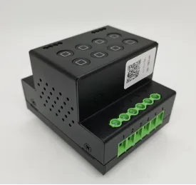
Function Overview
- A centralized control module that supports bus wired dry contact control and quick port connection design, significantly reducing maintenance costs. Group address function, batch execution of multiple scene control with one instruction, easily achieving preset scenarios such as single point, multi-point, area, and group control.
Applicable scenarios
- Widely applicable to users with centralized control needs such as homes, office buildings, hotels, hospitals, schools, stations, sports centers, museums, exhibition centers, factories, agriculture, shopping malls, etc.
Product Parameters
- Product Name: 8-way Centralized Control Relay Module
- Version: V3.5
- Product Model: M8162
- Shell Material: Sheet Metal
- Color: Black
- Installation Method: Standard DN35 Rail
- Size: 69*57* 87mm
- Weight and gross weight: 0.45kg
- Relay: 8-way self holding 16A
- Speed interface: MQPORT
- Communication: bus, wired
- Bus: RS485
- Baud rate: 9600
- Control protocol: Custom/Modbus protocol (Modbus independent version)
- Controlled protocol 1: Open
- Controlled protocol 2: Custom
- Power supply voltage: 12V
- Power supply current: 2A
- Release date: October 2023
Features
- Creating an exquisite appearance, the sheet metal shell is applied to the centralized control module, the internal structure is finely designed, and the appearance structure is protected by patents.
- Extra large terminal post, easy wiring, integrated design of common terminal, no need for jumper wires.
- Standard configuration includes 8-way self holding dual coil relay, 16A high power, strong load capacity, low power consumption, no heating, and long service life.
- Quickly plug and unplug connection terminals, and quickly connect communication power between modules.
- Integrated design back card, DN35 standard track, easy access to module.
- Exquisite car grade, with status display button, intuitive and convenient.
- Support any active RS485 panel access, the most common panel solution.
- Supports wireless scene panel access through M001 MESH, expanding the most flexible panel solution.
- Supports RS485 bus and wired multiple control modes.
- Outstanding reaction speed, anti-interference ability, and stability.
- Can quickly connect to bus panels with active sending function and a baud rate of 9600.
- supports feedback, receiving custom control instructions while also providing feedback on standard status protocols, compatible with both third-party panels and third-party bus control systems.
- Group address function, batch execution of scene control with one instruction, easily realizing scene presets such as single point, multi-point, area, and group control, reducing bus occupancy. For example, one instruction can put hundreds of circuit lights on a building in different scene states.
- Paired with multiple intelligent accessories to achieve personalized scene control.
- Remote control, real-time control (needs to be used in conjunction with an intelligent control system).
- Fearless of network disconnection, able to control even in the absence of network.
- supports running off the host and sending custom scene commands.
- supports access to third-party bus control systems and enables bidirectional communication.
- supports full customization of input control protocols and output control protocols.
- supports delayed closing and opening between 1-255s.
- supports button locking to prevent accidental touch.
- supports timed power on/off (needs to be used in conjunction with an intelligent control system).
- supports voice control (needs to be paired with an intelligent control system or an offline voice control module).
- Power on State Configuration Protocol, which allows customization of the power on or off state for any number of output channels.
- Custom staircase protocol, which allows customization of the delay and opening/closing sequence between relays.
Usage
M8162 Basic Usage Tutorial
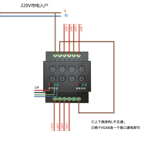
- Module Appearance Interface, Module Hardware Connection.
- A. The module interface consists of two MQPORTs from left to right, which are used to quickly connect the previous module from the left and the next module from the right, connecting communication and power supply.
- B. Extra large terminal post, 1 2 3 4 5 6 7 8 interface for load connection, L connected to live wire (the L in the upper and lower rows are not interconnected).
- C. The back is equipped with a standard DN35 spring buckle.
- D. There are 8 wired input buttons on the front, and the button indicator lights correspond to the relay switch status.
- E. The blue background light indicates the power supply status of the module.
Bus Control Usage Method
Address Modification
- After the device is powered on, it will automatically provide a 5-byte address feedback (for example, the address is 1A 13 24 56 91, which will be replaced with XX XX XX XX XX in the following text).
- Send XX XX XX XX (old address) F8 E7 D6 (fixed) XX XX XX XX XX XX XX XX (new address). Example: 1A 13 24 56 91 F8 E7 D6 1A 33 57 26 82 Change the old address 1A 13 24 56 91 to the new address 1A 33 57 26 82.
- Example: 1A 13 24 56 91 F8 E7 D6 1A 33 57 26 82 Change the old address 1A 13 24 56 91 to the new address 1A 33 57 26 82.
Branch group control
- Address wildcard: FF.
- Broadcast address: FF FF FF FF FF.
- FF can be located at any position of the five byte address in XX XX XX XX XX XX.
- Modify address splitting to achieve group control and scenario control through the configuration of addresses and wildcard characters.
- Example:
- Sending protocol XX XX XX XX FF: A module that can control 254 addresses from XX XX XX XX 00 to XX XX XX XX XX FE.
- Sending Protocol XX FF XX XX: Can control modules with a total of 254 * 254 addresses, including XX 00 00 XX XX - XX FE FE XX XX.
- Sending protocol FF FF XX FF XX: Can control modules with a total of 254 addresses, including 00 00 XX 00 XX - FE FE XX FE XX254.
- Sending protocol FF FF FF XX: Can control modules with a total of 254 addresses, including 00 00 00 XX - FE FE FE XX.254254 * 254 addresses.
- Sending protocol FF FF FF FF FF: Can control all modules.
Single channel control instruction
- XX XX XX XX XX XX (address) 00 (fixed) 00 (number of channels) 02 (function) 0F.
- Number of channels: 00 01 02 03 04 05 06 07 correspond to channels 1-8 respectively.
- Function: 02 on/off, 01 on, 00 off, 03 jog.
- Example: The first switch of XX XX XX XX 00 00 02 0F is flipped.
Multi channel overall operation instruction
- 01-08 fully open/fully closed: XX XX XX XX XX (address) 01 (01 fully open/02 fully closed) 77 88 0F.
- Example: XX XX XX XX 01 77 88 0F, switch 1-8 is fully open.
Composite operation instruction (1 instruction controls 8 relays)
- XX XX XX XX XX XX (address) CA (fixed) 00 (number of channels) 02 (function) 01 (number of channels) 02 (function)... 07 (number of channels) 02 (function) 0F.
- Number of channels: 00 01 02 03 04 05 06 07 correspond to channels 1-8 respectively.
- Function: 02 on/off, 01 on, 00 off, 03 jog, 04 maintain original state.
- Example: XX XX XX XX CA 00 01 01 02 03 00 04 00 05 00 06 02 02 0F.
- Turn on the first, second, third, fourth, fifth, sixth, seventh, and eighth paths.
Status query instruction
- sends XX XX XX XX (address) 86 86 86 0F.
- Feedback XX XX XX XX XX XX (address) 00 00 00 01 00 01 01 01 01 00 01 01 01 00 01 0F (00 close 01 open).
- Example: Send XX XX XX XX 86 86 0F.
- Feedback XX XX XX XX 00 00 00 01 01 00 01 01 00 01 01 00 01 01 00 01 0F.
- indicates that the status of channels 1-8 is off, off, on, or off.
Stair protocol instruction
- XX XX XX XX XX XX (address) CB (function) 00 03 (time interval for sequentially opening) 00 04 (time interval for keeping all open) 00 05 (time interval for sequentially closing) 0F.
- Time interval for sequentially opening, range 00 00 00- FF FF, time unit 0.1 second.
- The time to keep all open, ranging from 00 to FF FF, with a time unit of 0.1 seconds.
- The time interval for sequentially closing, ranging from 00 00 to FF FF, with a time unit of 0.1 seconds.
- Function: CD opens in a forward direction sequentially; CE opens in reverse order.
- Example: XX XX XX XX CD 00 03 00 04 00 05 0F.
- Open sequentially in a forward direction, with a time interval of 0.3 seconds between each opening; Keep all open for 0.4 seconds; The time interval for sequentially closing is 0.5 seconds.
Custom Stair Instructions
- XX XX XX XX XX XX (Address) D3 (Fixed) 00 01 (Delay Interval) 01 (01 On/00 Off/02 Flip) 01 (01 Forward/11 Reverse) 01 (Fixed) 0F.
- Delay Interval, Range 00 00 00 FF FF, Time Unit 0.1 Second.
- Example: XX XX XX XX D3 00 05 01 01 0F.
- Open sequentially in the forward direction, with a delay time interval of 0.5 seconds between opening.
Custom Instruction (Input Control Output)
- XX XX XX XX XX XX (Address) BB 00 (Fixed) 00 (Number of Input Channels) F1 (Input Status) CA (Fixed) 00 (Number of Output Channels) 02 (Output Function) 01 (Number of Output Channels) 02 (Output Function)... 06 (Number of Output Channels) 02 (Output Function) 07 (Number of Output Channels) 02 (Output Function) 0F.
- Input Control Output: When input button 1 is turned on, output 1-8 relays perform switch operations.
- Input channels: 00-07 correspond to channels 1-8 respectively.
- Input status: F1 represents long press, F2 represents single click, F3 represents double click.
- Output channels: 00-07 correspond to channels 1-8 respectively.
- Output function: 02 on/off, 01 on, 00 off, 03 jog, 04 maintain original state.
- Example: XX XX XX XX XX BB 00 00 F1 CA 00 01 01 01 02 01 03 00 04 00 05 00 06 02 07 02 0F. When the input button 1 is long pressed, the switch operations of relays 1-16 are as follows: the first channel is turned on, the second channel is turned on, the third channel is turned on, the fourth channel is turned off, the fifth channel is turned off, the sixth channel is turned off, the seventh channel is flipped, and the eighth channel is flipped.
- When the input button 1 is long pressed, the switching operations of relays 1-16 are as follows: the first channel is turned on, the second channel is turned on, the third channel is turned on, the fourth channel is turned off, the fifth channel is turned off, the sixth channel is turned off, the seventh channel is flipped, and the eighth channel is flipped.
Delete Custom Instruction Configuration
- XX XX XX XX XX (Address) BB 00 (Fixed) 00 (Number of Input Channels) F1 (Input Status) EE (Fixed) 0F.
- Number of Input Channels: 00-07 correspond to channels 1-8 respectively.
- Input status: F1 represents long press, F2 represents single click, F3 represents double click.
- Example: XX XX XX BB 00 07 F1 EE 0F Delete the configuration for the 8th route on time.
Input and send custom bus data command
- XX XX XX XX XX XX (address) BB 00 (fixed) 00 (input channels) E1 (input status) 01 (storage) YY YY YY YY YY YY YY YY YY YY YY YY YY YY (custom bus data) 0F.
- This custom protocol can be used to control bus controlled devices.
- Input channels: 00-07 correspond to channels 1-8 respectively.
- Input status: E1 relay on/E2 relay off/E3 click/E4 double-click/E5 long press.
- Storage: 01-06 represents the 1st to 6th storage. Each channel can store 6 instructions when connected and 6 instructions when disconnected. Each channel supports a total of 12 storage instructions.
- Example: XX XX XX BB 00 00 E1 01 12 35 03 01 FC 4A 0F.
- The first storage of the first channel: When the first channel is connected, send curtain bus data 12 35 03 01 FC 4A 0F, open the curtains.
Delete custom bus data
- XX XX XX XX XX (address) BB 00 (fixed) 00 (number of input channels) E1 (input status) EE (fixed) 0F.
- Input channels: 00-07 correspond to channels 1-8 respectively.
- Input status: E1 relay on/E2 relay off/E3 click/E4 double-click/E5 long press.
- Example: XX XX XX BB 00 03 E2 EE 0F Delete data when input path 4 is disconnected.
Configure the bus data transmission interval
- XX XX XX XX XX XX (address) BB D1 (fixed) 00 08 (interval time) 0F.
- Set the bus data transmission time based on the performance of the controlled product.
- Interval time 01-FF corresponds to 1-255 seconds.
- Delay unit: 50 milliseconds.
- Interval Time: Set the bus data transmission interval delay to 8 * 50=400 milliseconds.
- Example: XX XX XX BB D1 00 02 0F Set the bus data transmission time interval delay to 100 milliseconds.
Delete all input configuration data
- XX XX XX XX XX (Address) BB EE EE EE EE 0F Delete all data from channel 16.
Lock button command
- Lock button, fully open switch: XX XX XX XX XX (address) EC 00 0F FF 0F.
- Lock button, fully closed switch: XX XX XX XX XX XX (address) EC 00 00 00 0F.
Unlock button command
- Unlock button, fully open switch: XX XX XX XX XX (address) EC 01 0F FF 0F.
- Unlock button, fully closed switch: XX XX XX XX XX XX (address) EC 01 00 00 0F.
Switch Delay Configuration (This mode requires configuring the keys to jog mode)
- XX XX XX XX XX XX (Address) 9F (Fixed) 01 (Number of Channels) 01 (Time) 0F.
- Channels: 00-07 correspond to channels 1-8 respectively.
- Time: 01-FF corresponds to 1-255 seconds.
- Example: XX XX XX XX 9F 07 06 0F 8th channel delayed by 6 seconds.
Power on initial state configuration instruction
- XX XX XX XX XX (address) EA (fixed) 00 (number of channels) 01 (01 on/00 off) 01 (number of channels) 00 (01 on/00 off) 02 (number of channels) 01 (01 on/00 off)... 07 (number of channels) 01 (01 on/00 off) 0F.
- Number of channels: 00-07 correspond to channels 1-8 respectively.
- Every 2 bytes form 1 group, set the initial state for power on, 01 on/00 off.
- The default initial state when powered on is off.
- Example: XX XX XX EA 00 01 00 02 01 0F. When initially powered on, the first circuit is turned on, the second circuit is turned off, and the third circuit is turned on.
- When initially powered on, the first circuit is turned on, the second circuit is turned off, and the third circuit is turned on.
- Note: After the self holding relay is powered off, it will maintain the state before power off, and when powered on, it will switch whether to switch on or off according to the power on configuration.
Feedback Mode Configuration Protocol
- XX XX XX XX XX (Address) BB D2 00 (Fixed) 00 (00 opens standard active feedback/01 opens custom active feedback/03 closes active feedback) 0F.
- Feedback is divided into standard feedback and custom feedback.
- Standard Active Feedback: Feedback XX XX XX XX (address) 16 byte switch status (0 off/1 on) 0F.
- Custom Active Feedback: Feedback the custom bus data configured in the input send custom bus data instruction.
- Example: XX XX XX XX BB D2 00 00 0F Open standard active feedback.
- Send XX XX XX XX XX 86 86 0F.
- Feedback: XX XX XX XX 00 00 00 01 01 00 00 01 01 01 01 00 01 01 01 00 01 01 01 01 01 0F indicates that the status of channels 1-8 is off, off, on/off.
Packing List
- 8-way Centralized Control Relay Module M8162
- Manual
- Warranty Card
- Certificate of Conformity
Attention: Please carefully read this manual before use to ensure correct installation and use of the product. If you have any questions, please contact professional technicians or after-sales service.


Leave a Reply