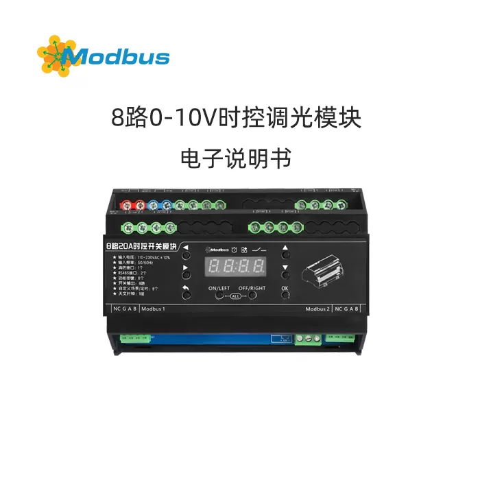
1. Product Introduction
CY-SW0820A 8-way 20A switch module is a core execution unit designed specifically for intelligent lighting control systems. It integrates 8-way independent magnetic holding relays, each supporting 20A high load on/off control (maximum load of 4400W per circuit), which can achieve precise switch management of various equipment such as lighting, sockets, electric curtains, air conditioning, etc. It is installed in a 35mm standard rail style.
Function Description:
- Built in power supply, no need for external power module
- Equipped with 8 function keys, used for switching status, setting baud rate, slave address, time and date, and other functions
- Supports astronomical clock timing and can execute custom scenes based on sunrise, sunset, and week status
- Supports 8-week timed execution, allowing for customized scenarios based on time and week status
- The module is equipped with 8 built-in 20A relay switches, with a maximum power of 4400W per circuit
- Equipped with RS485 control serial port, supports Modbus RTU communication protocol, and can communicate up to 1200 meters at 9600 baud rate for easy debugging and control
- Comes with 1 LED digital tube, the device's working status is clear at a glance
- comes with a built-in fire interface that supports passive and active 12V signal access, achieving fire linkage
- adopts a 35mm rail mounted installation
Technical Parameters
| Project | Parameters |
|---|---|
| Product Model | CY-SW0820T |
| Product Name | 8-Channel 20A Time Control Switch Module |
| Input Voltage | 110~230VAC ± 10% |
| Input Frequency | 50/60Hz |
| Switch Output | 8 routes (single route 20A) |
| RS485 control serial port | 2, 9600, N, 8,1, supports Modbus RTU protocol |
| Support baud rate | 1200/2400/4800/9600/19200/38400, N,8,1 |
| Weekly schedule | 8 groups |
| Astronomical clock | 1 group (supports sunrise and sunset timing) |
| custom scenario | 8 of them |
| function key | 8 of them |
| Display digital tube | 1 piece |
| Slave address range | 1-63 |
| Operating Temperature | -5℃~45℃ |
| Relative humidity at work | ≤90% |
| Storage temperature | -20℃~60℃ |
| Store relative humidity | ≤93% |
| Dimensions | 114mm98mm72mm |
| Protection Class | IP20 |
| Net Weight | 558g/pcs |
| Installation Method | 35mm Rail Installation |
1. Product Interface Diagram (Text Description)
- Left: Power Input AC110~230V
- Central: 8 sets of relay output terminals WL1-WL8 (20A per channel)
- Right:
- MODBUS1 interface: A, B, G (RS485)
- MODBUS2 interface: A, B, G (RS485)
- Fire interface:
- Passive: 1-2 short circuit → 1-8 channels fully open
- Active: DC12V connected to 2-3 → 1-8 channels fully open
- Digital tube and 8 function buttons (ON/EFT, OFF/RIGHT, OK, etc.)
2. Product size diagram (text description)
144mm (Length) x 98mm (Width) x 72mm (Height), with a 35mm rail buckle located on the back.
3. Schematic diagram of a single system (text description)
AC IN → module → 8 loads (each ≤ 4400W)
RS485 bus: PC/PLC → module (up to 63 in series, head to tail ≤ 300m)
4. Multi system schematic diagram (textual description)
Multiple electrical boxes (NAL1, NAL2...) are connected hand in hand through RS485 and ultimately connected to PC configuration software, with a maximum of 63 modules.
II. Communication Interface
1. Communication Format
| Communication Format (baud rate, data bits, stop bits, parity) | Remarks |
|---|---|
| 1200, N, 8,1 | Optional |
| 2400, N, 8,1 | Optional |
| 4800, N, 8,1 | Optional |
| 9600, N,8,1 | Factory default |
| 19200, N,8,1 | Optional |
| 38400, N,8,1 | Optional |
2. From the station address
- Address range: 0x01-0x3F (decimal 1-63)
- Address setting: Set through physical buttons on the module panel (see Control Panel chapter)
3. Protocol Format Explanation
- Supports Modbus RTU protocol
- Verification methods are optional:
- Fixed two byte 0xAC 0xAC
- Or standard CRC16 (low byte first, high byte second)
3, Function code description (complete)
1. Function Code 03H: Read and Hold Register
Host → Slave: 01 03 00 02 00 02 65 CB
- 01: Slave Address
- 03: Function Code
- 00 02: Start Register Address 0002H
- 00 02: Read Register Quantity 2
- 65 CB: CRC16 Verification
Machine → Host: 01 03 04 00 FE 00 41 5B F3
- 01: Slave Address
- 03: Function Code
- 04: Return Byte Count 4
- 00 FE: Register 0002H Value
- 00 41: Register 0003H Value
- 5B F3: CRC16 Check
2. Function Code 06H: Write Single Register
Host → Slave: 01 06 00 03 00 41 B9 FA
- 01: Slave Address
- 06: Function Code
- 00 03: Register Address 0003H
- 00 41: Write Value 0041H (decimal 65)
- B9 FA: CRC16 checksum
Slave → Host: returns exactly the same as the host request
3. Function code 10H: writes multiple registers
Host → Slave: 01 10 00 01 00 02 04 00 01 00 FE E2 23
- 01: Slave address
- 10: Function code
- 00 01: Start register address 0001H
- 00 02: Write 2 registers
- 00 31] E2 23: CRC16 verification
- 00 01: Register 0001H value
- 00 FE: Register 0002H value
- E2 23: CRC16 verification
Slave → Host: 01 10 00 01 00 02 10 08
- 10 08: CRC16 verification
4. Function code 01H: Read coil status (switch status)
Host → Slave: 01 01 00 00 08 3D CC
- 01: Slave address
- 01: Function code
- 00 00: Start coil address 0000H
- 00 08: Read coil quantity 8
- 3D CC: CRC16 verification
Slave → Host: 01 01 01 FF 11 C8
- BI_143] FF: bit0-bit7 corresponds to coil 1-8 status (1 on 0 off)
- FF: bit0-bit7 corresponds to coil 1-8 status (1 on 0 off)
- 11 C8: CRC16 verification
5. Function code 05H: Write single coil (single switch)
Host → Slave: 01 05 00 FF 00 8C 3A
- 01: Slave address
- 05: Function code
- 00 00: Coil address 0000H (loop 1)
- FF 00: Write "on"
- 8C 3A: CRC16 verification
Slave → Host: Return exactly the same as the host request
6. Function code 0FH: Write multiple coils (multiple switches)
Host → Slave Machine: 01 0F 00 00 00 08 01 0F BE 91
- 01: Slave station address
- 0F: Function code
- 00 00: Starting coil address 0000H
- 00 08: Number of written coils 8
- 01: Number of written bytes 1
- 0F: Write value 00001111B (circuit 1-4 on, 5-8 off)
- BE 91: CRC16 verification
Slave → Host: 01 0F 00 00 00 08 54 0D
IV. Register address table
1. Simplified register address table (complete)
| Function | Register Dec | Register Hex | Data Range Hex | Read/Write | Function Code | Remarks |
|---|---|---|---|---|---|---|
| Dimming Circuit 1-8 | 0-7 | 0000H-0007H | High Bit 00 Low Bit 00-64 (0-100%) | R/W | 03/06/10 | When writing multiple channels with 10H, Low Bit=FFH not executed |
| Scene Configuration Register | 64-71 | 0040H-0047H | High Bit 00 Low Bit 00-01 (default FF) | R/W | 06/10 | 8 scenes, 8 registers per scene |
| 72-79 | 0048H-004FH | Same as | Same as | Same as | Scene 2 | |
| 80-87 | 0050H-0057H | Same as | Same as | Same as | Scene 3 | |
| 88-95 | 0058H-005FH | Same as above | Same as above | Same as above | Scene 4 | |
| 96-103 | 0060H-0067H | Same as above | Same as above | Same as above | Scene 5 | |
| 104-111 | 0068H-006FH | Same as above | Ditto. | Ditto. | Scenario 6 | |
| 112-119 | 0070H-0077H | Ditto. | Ditto. | Ditto. | Scenario 7 | |
| 120-127 | 0078H-007FH | Ditto. | Ditto. | Ditto. | Scenario 8 | |
| Power on brightness register | 136-143 | 0088H-008FH | High level 00, low level 00=off 01=on FF=power-off recovery | R/W | 03/06/10 | Corresponding to circuits 1-8 |
| Time and date settings | 184-190 | 00B8H-00BEH | Year 0000-0063 (0-99) Month 0001-000C (1-12) Day 0001-001F (1-31) Hour 0000-0017 (0-23) Minute 0000-003B (0-59) Second 0000-003B (0-59) Week 0001-0007 (read-only) | R/W | 03/06/10 | Register B8-BE |
| Scene call register sequentially | 191 | 00BFH | High 00 Low 01-08 (Scenario 1-8) High FF=Close Scene | W | 06 | Write and call |
| Baud rate setting | 192 | 00C0H | High 00 and low 0000-0005 correspond to 1200-38400 | R/W | 03/06 | Left RS485 |
| 193 | 00C1H | Ditto. | Ditto. | Ditto. | Right RS485 | |
| Factory register | 194 | 00C2H | High level 00, low level 01=factory reset | W | 06 | After writing 01, all modules are restored to default |
| Version Register | 195-197 | 00C3H-00C5H | Read only, in sequence: Year (2025=07E9H) Month Day (0519=0207H) Version (0100=0064H) | R | 03 | Actual production shall prevail |
| Weekly timer (12 registers per timer) | 216-227 | 00D8H-00E3H | Switch 0000/0001 hour 0000-0017 minute 0000-003B week 0000-007F (bit0-6 corresponds to Monday day) circuit 1-8 status 0000/0001 or 00FF not executed | R/W | 03/06/10 | Timer 1 |
| 228-239 | 00E4H-00EFH | Same as | Same as | Same as | Timer 2 | |
| 240-251 | 00F0H-00FBH | Same as | Same as | Same as | Timer 3 | |
| 252-263 | 00FCH-0107H | Same as | Same as | Same as | Timer 4 | |
| 264-275 | 0108H-0113H | Same as | Same as | Same as | Timer 5 | |
| 276-287 | 0114H-011FH | Same as | Ditto. | Ditto. | Timer 6 | |
| 288-299 | 0120H-012BH | Ditto. | Ditto. | Ditto. | Timer 7 | |
| 300-311 | 012CH-0137H | Ditto. | Ditto. | Ditto. | Timer 8 | |
| latitude and longitude | 320-322 | 0140H-0142H | East/West longitude (low position 00/01) degrees 0-180 points 0-59 | R/W | 03/06/10 | Default Guangzhou |
| latitude | 323-325 | 0143H-0145H | North/South latitude (low position 00/01) degrees 0-180 minutes 0-59 | Ditto. | Ditto. | Default Guangzhou |
| Sunrise Time | 326-327 | 0146H-0147H | Read only, hours 0000-0017 minutes 0000-003B | R | 03 | Calculation Result |
| Sunset Time | 328-329 | 0148H-0149H | Same as | Same as | Same as | Same as |
| Sunrise Timing | 330-339 | 014AH-0153H | Switch 0000/0001 Week 0000-007F Circuit 1-8 Status 0000/0001 or 00FF not executed | R/W | 03/06/10 | Ditto. |
| Sunset timer | 340-349 | 0154H-015DH | Ditto. | Ditto. | Ditto. | Ditto. |
| Auxiliary register | 2001-2064 | 07D1H-0810H | Write only, 10H function code, 8 registers/group, currently only using switch bits, the rest reserved; If the gradient time or brightness is FFH, skip this path | W | 10 | Please refer to the auxiliary table |
2. Loop Control Register Address (Complete)
| Function | Loop 1 | Loop 2 | Loop 3 | Loop 4 | Circuit 5 | Circuit 6 | Circuit 7 | Circuit 8 |
|---|---|---|---|---|---|---|---|---|
| Register Hex | 0000H | 0001H | 0002H | 0003H | 0004H | 0005H | 0006H | 0007H |
3. Scene setting register address (complete)
| Scene | Circuit 1 | Circuit 2 | Circuit 3 | Circuit 4 | Circuit 5 | Circuit 6 | Circuit 7 | Circuit 8 |
|---|---|---|---|---|---|---|---|---|
| 1 | 0040H | 0041H | 0042H | 0043H | 0044H | 0045H | 0046H | 0047H |
| 2 | 0048H | 0049H | 004AH | 004BH | 004CH | 004DH | 004EH | 004FH |
| 3 | 0050H | 0051H | 0052H | 0053H | 0054H | 0055H | 0056H | 0057H |
| 4 | 0058H | 0059H | 005AH | 005BH | 005CH | 005DH | 005EH | 005FH |
| 5 | 0060H | 0061H | 0062H | 0063H | 0064H | 0065H | 0066H | 0067H |
| 6 | 0068H | 0069H | 006AH | 006BH | 006CH | 006DH | 006EH | 006FH |
| 7 | 0070H | 0071H | 0072H | 0073H | 0074H | 0075H | 0076H | 0077H |
| 8 | 0078H | 0079H | 007AH | 007BH | 007CH | 007DH | 007EH | 007FH |
4. Power on status register address (complete)
| function | Loop 1 | Loop 2 | Loop 3 | Loop 4 | Loop 5 | Loop 6 | Loop 7 | Loop 8 |
|---|---|---|---|---|---|---|---|---|
| Register Hex | 0088H | 0089H | 008AH | 008BH | 008CH | 008DH | 008EH | 008FH |
5. Time Date Register Address (Complete)
| Function | Year | Month | Day | Time | Divide | Seconds | Week |
|---|---|---|---|---|---|---|---|
| Register Hex | 00B8H | 00B9H | 00BAH | 00BBH | 00BCH | 00BDH | 00BEH |
6. Weekly timer register address (complete, 12 registers per timer)
| Timer | switch | hour | minute | Week | Circuit 1-8 status |
|---|---|---|---|---|---|
| 1 | 00D8H | 00D9H | 00DAH | 00DBH | 00DCH-00E3H |
| 2 | 00E4H | 00E5H | 00E6H | 00E7H | 00E8H-00EFH |
| 3 | 00F0H | 00F1H | 00F2H | 00F3H | 00F4H-00FBH |
| 4 | 00FCH | 00FDH | 00FEH | 00FFH | 0100H-0107H |
| 5 | 0108H | 0109H | 010AH | 010BH | 010CH-0113H |
| 6 | 0114H | 0115H | 0116H | 0117H | 0118H-011FH |
| 7 | 0120H | 0121H | 0122H | 0123H | 0124H-012BH |
| 8 | 012CH | 012DH | 012EH | 012FH | 0130H-0137H |
7. Setting register address for sunrise and sunset (complete)
| Function | switch | Week | Circuit 1-8 status |
|---|---|---|---|
| Sunrise timing | 014AH | 014BH | 014CH-0153H |
| Sunset timer | 0154H | 0155H | 0156H-015DH |
8. Auxiliary register address (complete, 8 x 8 registers)
| Loop | Register 1 | Register 2 | Register 3 | Register 4 | Register 5 | Register 6 | Register 7 | Register 8 |
|---|---|---|---|---|---|---|---|---|
| 1 | 07D1H | 07D2H | 07D3H | 07D4H | 07D5H | 07D6H | 07D7H | 07D8H |
| 2 | 07D9H | 07DAH | 07DBH | 07DCH | 07DDH | 07DEH | 07DFH | 07E0H |
| 3 | 07E1H | 07E2H | 07E3H | 07E4H | 07E5H | 07E6H | 07E7H | 07E8H |
| 4 | 07E9H | 07EAH | 07EBH | 07ECH | 07EDH | 07EEH | 07EFH | 07F0H |
| 5 | 07F1H | 07F2H | 07F3H | 07F4H | 07F5H | 07F6H | 07F7H | 07F8H |
| 6 | 07F9H | 07FAH | 07FBH | 07FCH | 07FDH | 07FEH | 07FFH | 0800H |
| 7 | 0801H | 0802H | 0803H | 0804H | 0805H | 0806H | 0807H | 0808H |
| 8 | 0809H | 080AH | 080BH | 080CH | 080DH | 080EH | 080FH | 0810H |
5, Protocol routine
1. Write a single switch instruction register (function code 05H)
| Serial number | Instruction (CRC16 can fix AC AC) | feedback | Annotation |
|---|---|---|---|
| 1 | 01 05 00 00 FF 00 8C 3A | 01 05 00 00 FF 00 8C 3A | Circuit 1 is open |
| 2 | 01 05 00 01 FF 00 DD FA | 01 05 00 01 FF 00 DD FA | Circuit 2 is open |
| 3 | 01 05 00 02 FF 00 2D FA | 01 05 00 02 FF 00 2D FA | Circuit 3 is open |
| 4 | 01 05 00 03 FF 00 7C 3A | 01 05 00 03 FF 00 7C 3A | Circuit 4 is open |
| 5 | 01 05 00 04 FF 00 CD FB | 01 05 00 04 FF 00 CD FB | Circuit 5 is turned on |
| 6 | 01 05 00 05 FF 00 9C 3B | 01 05 00 05 FF 00 9C 3B | Circuit 6 is turned on |
| 7 | 01 05 00 06 FF 00 6C 3B | 01 05 00 06 FF 00 6C 3B | Circuit 7 is turned on |
| 8 | 01 05 07 FF 00 3D FB | 01 05 00 07 FF 00 3D FB | Circuit 8 is turned on |
| 9 | 01 05 00 00 00 00 CD CA | 01 05 00 00 00 00 CD CA | Circuit 1 is closed |
| 10 | 01 05 00 00 00 00 9C 0A | 01 05 00 01 00 00 9C 0A | Circuit 2 is closed |
| 11 | 01 05 00 02 00 6C 0A | 01 05 00 00 00 6C 0A | Circuit 3 is closed |
| 12 | 01 05 00 03 00 3D CA | 01 05 00 03 00 3D CA | Circuit 4 is closed |
| 13 | 01 05 00 04 00 00 8C 0B | 01 05 00 04 00 00 8C 0B | Circuit 5 closed |
| 14 | 01 05 00 00 00 DD CB | 01 05 00 05 00 00 DD CB | Circuit 6 closed |
| 15 | 01 05 00 06 00 00 2D CB | 01 05 00 06 00 2D CB | Circuit 7 closed |
| 16 | 01 05 00 07 00 7C 0B | 01 05 00 07 00 7C 0B | Circuit 8 closed |
2. Write Single Dimming Instruction Register (Function Code 06H)
| Serial Number | Instruction (CRC16 can fix AC) | Feedback | Annotation |
|---|---|---|---|
| 1 | 01 06 00 00 00 64 88 21 | 01 06 00 00 00 64 88 21 | Loop 1 Brightness 100% |
| 2 | 01 06 00 01 00 64 D9 E1 | 01 06 00 01 00 64 D9 E1 | Loop 2 Brightness 100% |
| 3 | 01 06 00 02 00 64 29 E1 | 01 06 00 02 00 64 29 E1 | Loop 3 Brightness 100% |
| 4 | 01 06 00 03 00 64 78 21 | 01 06 00 03 00 64 78 21 | Loop 4 Brightness 100% |
| 5 | 01 06 00 04 00 64 C9 E0 | 01 06 00 04 00 64 C9 E0 | Loop 5 Brightness 100% |
| 6 | 01 06 00 05 00 64 98 20 | 01 06 00 05 00 64 98 20 | Loop 6 Brightness 100% |
| 7 | 01 06 00 06 00 64 68 20 | 01 06 00 06 00 64 68 20 | Loop 7 Brightness 100% |
| 8 | 01 06 00 07 00 64 39 E0 | 01 06 00 07 00 64 39 E0 | Loop 8 Brightness 100% |
| 9 | 01 06 00 00 00 89 CA | 01 06 00 00 00 89 CA | Loop 1 Brightness 0% |
| 10 | 01 06 00 00 00 00 D8 0A | 01 06 00 01 00 00 D8 0A | Loop 2 Brightness 0% |
| 11 | 01 06 00 02 00 28 0A | 01 06 00 02 00 28 0A | Loop 3 Brightness 0% |
| 12 | 01 06 00 03 00 79 CA | 01 06 00 03 00 79 CA | Loop 4 Brightness 0% |
| 13 | 01 06 00 04 00 C8 0B | 01 06 00 04 00 C8 0B | Loop 5 Brightness 0% |
| 14 | 01 06 00 05 00 99 CB | 01 06 00 00 00 99 CB | Loop 6 Brightness 0% |
| 15 | 01 06 00 00 69 CB | 01 06 00 06 00 69 CB | Loop 7 Brightness 0% |
| 16 | 01 06 00 07 00 38 0B | 01 06 00 07 00 38 0B | Loop 8 Brightness 0% |
3. Write Multi way Switch Instruction Register (Function Code 0FH)
| Serial Number | Instruction (CRC16 can fix AC) | Feedback | Annotation |
|---|---|---|---|
| 1 | 01 0F 00 00 00 08 01 FF BE D5 | 01 0F 00 00 00 08 54 0D | Circuit 1-8 fully open |
| 2 | 01 0F 00 00 00 08 01 00 FE 95 | 01 0F 00 00 00 08 54 0D | Circuit 1-8 is fully closed |
| 3 | 01 0F 00 00 00 08 01 0F BE 91 | 01 0F 00 00 00 08 54 0D | Circuit 1-4 is open, 5-8 is closed |
| 4 | 01 0F 00 00 00 08 01 F0 FE D1 | 01 0F 00 00 00 08 54 0D | Circuit 1-4 closed, 5-8 open |
4. Write multiple dimming instruction registers (function code 10H)
| serial number | Instruction (CRC16 can fix AC) | Feedback | Annotations |
|---|---|---|---|
| 1 | 01 10 00 00 08 10 00 64 00 64 00 64 00 64 00 64 00 64 00 64 00 64 00 64 00 97 0B | 01 10 00 00 08 C1 CF | Loop 1-8 Brightness 100% |
| 2 | 01 10 00 00 08 10 00 00 00 00 19 CD | 01 10 00 00 00 08 C1 CF | Loop 1-8 Brightness 0% |
| 3 | 01 10 00 00 00 08 10 00 64 00 64 00 64 00 64 00 00 00 00 00 00 00 00 00 83 31 | 01 10 00 00 00 08 C1 CF | Loop 1-4 brightness 100%, 5-8 brightness 0% |
| 4 | 01 10 00 00 00 08 10 00 00 00 00 00 00 00 00 00 64 00 64 00 64 00 64 0D F7 | 01 10 00 00 00 08 C1 CF | Circuit 1-4 brightness 0%, 5-8 brightness 100% |
5. Read switch status instruction register (function code 01H)
| serial number | instruction (CRC16 can fix AC) | feedback | annotation |
|---|---|---|---|
| 1 | 01 00 00 01 FD CA | 01 01 01 01 90 48 | Read single channel, circuit 1 open |
| 2 | 01 00 01 00 01 AC 0A | 01 01 01 01 90 48 | Read single channel, circuit 2 open |
| 3 | 01 01 00 02 00 01 5C 0A | 01 01 01 01 90 48 | Read single channel, circuit 3 open |
| 4 | 01 01 00 03 00 01 0D CA | 01 01 01 01 90 48 | Read single channel, circuit 4 open |
| 5 | 01 01 00 04 00 01 BC 0B | 01 01 01 01 90 48 | Read single channel, circuit 5 open |
| 6 | 01 01 00 05 00 01 ED CB | 01 01 01 01 90 48 | Read single channel, circuit 6 open |
| 7 | 01 01 00 06 00 01 1D CB | 01 01 01 01 90 48 | Read single channel, circuit 7 open |
| 8 | 01 01 00 07 00 01 4C 0B | 01 01 01 01 90 48 | Read single channel, circuit 8 open |
| 9 | 01 01 00 00 00 08 3D CC | 01 01 01 FF 11 C8 | Read channels 1-8, all open |
6. Read dimming status instruction register (function code 03H)
| Serial number | Instruction (CRC16 can fix AC AC) | feedback | Annotation |
|---|---|---|---|
| 1 | 01 03 00 00 00 01 84 0A | 01 03 02 00 64 B9 AF | Read single channel, circuit 1 brightness 100% |
| 2 | 01 03 00 01 00 01 D5 CA | 01 03 02 00 64 B9 AF | Read single channel, loop 2 brightness 100% |
| 3 | 01 03 00 02 00 01 25 CA | 01 03 02 00 64 B9 AF | Read single channel, loop 3 brightness 100% |
| 4 | 01 03 00 03 00 01 74 0A | 01 03 02 00 64 B9 AF | Read single channel, loop 4 brightness 100% |
| 5 | 01 03 00 04 00 01 C5 CB | 01 03 02 00 64 B9 AF | Read single channel, loop 5 brightness 100% |
| 6 | 01 03 00 05 00 01 94 0B | 01 03 02 00 64 B9 AF | Read single channel, loop 6 brightness 100% |
| 7 | 01 03 00 06 00 01 64 0B | 01 03 02 00 64 B9 AF | Read single channel, circuit 7, brightness 100% |
| 8 | 01 03 00 07 00 01 35 CB | 01 03 02 00 64 B9 AF | Read single channel, loop 8, brightness 100% |
| 9 | 01 03 00 00 00 08 44 0C | 01 03 10 00 64 00 64 00 64 00 64 00 64 00 64 00 64 6A 9F | Read channels 1-8, all with 100% brightness |
7. Write single channel dimming gradient time instruction register (function code 06H)
| Serial number | Instruction (CRC16 can fix AC AC) | feedback | Comments |
|---|---|---|---|
| 1 | 01 06 00 80 00 03 C8 23 | 01 06 00 80 00 03 C8 23 | Transition time of loop 1 is 3 seconds |
| 2 | 01 06 00 81 00 03 99 E3 | 01 06 00 80 00 03 C8 23 | Transition time 3 for loop 2 s |
| 3 | 01 06 00 82 00 03 69 E3 | 01 06 00 80 00 03 C8 23 | Loop 3 Gradient Time 3 s |
| 4 | 01 06 00 83 00 03 18 23 | 01 06 00 80 00 03 C8 23 | Transition time for loop 4 is 3 seconds |
| 5 | 01 06 00 84 00 03 89 E2 | 01 06 00 80 00 03 C8 23 | Loop 5 Gradient Time 3 s |
| 6 | 01 06 00 85 00 03 D8 22 | 01 06 00 80 00 03 C8 23 | Loop 6 Gradient Time 3 s |
| 7 | 01 06 00 86 00 03 28 22 | 01 06 00 80 00 03 C8 23 | Loop 7 Gradient Time 3 s |
| 8 | 01 06 00 87 00 03 79 E2 | 01 06 00 80 00 03 C8 23 | Transition time for loop 8 is 3 seconds |
8. Write multiple dimming gradient time instruction registers (function code 10H)
| Serial number | Instruction (CRC16 can fix AC AC) | feedback | Annotation |
|---|---|---|---|
| 1 | 01 10 00 80 00 08 10 00 03 00 03 00 03 00 03 00 03 00 03 00 03 00 03 9C 64 | 01 10 00 80 00 08 C0 27 | Transition time of loop 1-8 is 5 seconds |
| 2 | 01 10 00 80 00 08 10 00 00 00 00 00 00 00 00 00 00 00 00 00 00 00 00 06 13 | 01 10 00 80 00 08 C0 27 | Loop 1-8 gradient time 0 s (immediate) |
9. Call scene instruction register (function code 06H)
| Serial Number | Instruction (CRC16 can fix AC) | Feedback | Comments |
|---|---|---|---|
| 1 | 01 06 00 BF 00 01 79 EE | 01 06 00 BF 00 01 79 EE | Call Scenario 1 |
| 2 | 01 06 00 BF 00 02 39 EF | 01 06 00 BF 00 02 39 EF | Call Scenario 2 |
| 3 | 01 06 00 BF 00 03 2F | 01 06 00 BF 00 03 F8 2F | Call scenario 3 |
| 4 | 01 06 00 BF 00 04 B9 ED | 01 06 00 BF 00 04 B9 ED | Call scenario 4 |
| 5 | 01 06 00 BF 00 05 78 2D | 01 06 00 BF 00 05 78 2D | Call scenario 5 |
| 6 | 01 06 00 BF 00 06 38 2C | 01 06 00 BF 00 06 38 2C | Call scenario 6 |
| 7 | 01 06 00 BF 00 07 F9 EC | 01 06 00 BF 00 07 F9 EC | Call Scenario 7 |
| 8 | 01 06 00 BF 00 08 B9 E8 | 01 06 00 BF 00 08 B9 E8 | Call Scenario 8 |
10. Scene Configuration Instruction Register (Function Code 10H)
| Serial Number | Instruction (CRC16 can fix AC) | Feedback | Annotation |
|---|---|---|---|
| 1 | 01 10 00 40 00 08 10 00 64 00 64 00 64 00 64 00 64 00 64 00 99 C4 | 01 10 00 40 00 08 C0 1B | Configuration Scenario 1: Loop 1-8 open |
| 2 | 01 10 00 48 00 08 10 00 00 00 00 00 00 00 00 00 00 00 00 00 00 00 00 F6 4B | 01 10 00 48 00 08 41 D9 | Configuration scenario 2: Circuit 1-8 closed |
11. Power on status instruction register (function code 10H)
| Serial number | Instruction (CRC16 can fix AC AC) | feedback | Annotation |
|---|---|---|---|
| 1 | 01 10 00 88 00 08 10 00 FF 00 FF 00 FF 00 FF 00 FF 00 FF 00 FF 00 FF 11 6C | 01 10 00 88 00 08 41 E5 | Power on to restore the state before power off |
| 2 | 01 10 00 88 00 08 10 00 00 00 00 00 00 00 00 00 00 00 00 00 00 00 00 E7 5A | 01 10 00 88 00 08 41 E5 | Power on fully off |
| 3 | 01 10 00 88 00 08 10 00 64 00 64 00 64 00 64 00 64 00 64 00 64 00 64 69 9C | 01 10 00 88 00 08 41 E5 | Power on and fully open 100% |
12. Time and date read/write instruction register (function code 03H/10H)
| Serial number | Instruction (CRC16 can fix AC AC) | feedback | Annotation |
|---|---|---|---|
| 1 | 01 10 00 B8 00 06 0C 00 19 00 06 00 03 00 0D 00 32 00 00 96 57 | 01 10 00 B8 00 06 C0 2E | Set 2022-06-03 13:45:00 |
| 2 | 01 03 00 B8 00 07 84 2D | 01 03 0E 00 19 00 06 00 03 00 0D 00 38 00 09 00 02 EA F2 | Read back: 2022-06-03 13:38:09 Tuesday |
13. Sunrise and Sunset Timer Setting Instruction Register (Function Code 10H)
| Serial number | Instruction (CRC16 can fix AC AC) | feedback | Annotation |
|---|---|---|---|
| 1 | 01 10 01 4A 00 0A 14 00 01 00 7F 00 00 00 00 00 00 00 00 00 00 00 00 00 00 00 65 84 | 01 10 01 4A 00 0A 60 24 | Start the sunrise timer and execute it every day. The brightness of circuits 1-8 is 0% |
| 2 | 01 10 01 54 00 0A 14 00 01 00 7F 00 64 00 64 00 64 00 64 00 64 00 64 00 64 0A 82 | 01 10 01 54 00 0A 00 22 | Enable sunset timer, executed daily, loop 1-8 brightness 100% |
| 3 | 01 03 01 4A 00 0A E5 E7 | 01 03 14 00 01 00 7F 00 00 00 00 00 00 00 00 00 00 00 00 00 00 00 00 00 00 00 00 00 8E B3 | Read sunrise timer status: enabled, daily, loop 1-8 brightness 0% |
| 4 | 01 03 01 54 00 0A 85 E1 | 01 14 00 01 00 7F 00 64 00 64 00 00 64 00 00 00 64 00 00 64 00 00 64 00 75 | Read sunset timer status: enabled, daily, loop 1-8 brightness 100% |
14. Weekly timer Set instruction register (function code 03H/10H)
| serial number | instruction (CRC16 can fix AC) | Feedback | Comments |
|---|---|---|---|
| 1 | 01 10 00 D8 00 0C 18 00 01 00 08 00 00 1F 00 00 00 00 00 00 00 00 00 00 00 00 00 00 00 00 00 00 00 00 00 00 00 00 00 00 00 00 00 00 00 00 00 00 00 00 00 00 00 00 00 00 00 00 00 00 00 00 00 00 00 00 00 00 00 00 00 00 00 00 00 00 00 00 00 00 00 00 00 00 00 00 00 00 00 00 00 00 00 00 00 00 00 00 00 00 00 00 00 00 00 00 00 00 00 00 00 00 00 00 00 00 00 00 00 00 00 00 00 00 00 00 00 00 00 00 00 00 00 00 00 00 00 00 00 00 00 00 00 00 00 00 00 00 00 00 00 00 00 00 00 00 00 00 00 00 00 00 00 00 00 00 00 00 00 00 00 00 00 00 00 00 00 00 00 00, Circuit 1-8 brightness 100% | 01 10 00 D8 00 0C 40 37 | Start timer 1: Monday to Friday 08:00, circuit 1-8 brightness 0% |
| 2 | 01 10 00 E4 00 0C 18 00 01 00 12 00 00 00 1F 00 64 00 64 00 64 00 64 00 64 00 64 00 64 4C C1 | 01 10 00 E4 00 0C 80 3B | Start timer 2: Monday to Friday 18:00, circuit 1-8 brightness 100% |
| 3 | 01 03 00 D8 00 0C C5 F4 | 01 03 18 00 01 00 08 00 00 00 1F 00 00 00 00 00 00 00 00 00 00 00 00 00 00 00 00 00 00 00 00 00 00 00 00 00 00 00 00 00 00 00 00 00 00 00 00 00 00 10 16 | Read timing 1 status: Same as above |
| 4 | 01 03 00 E4 00 0C 05 F8 | 01 03 18 00 01 00 12 00 00 00 1F 00 64 00 64 00 64 00 64 00 64 00 64 00 64 26 EB | Read timing 2 status: Same as above |
15. Factory reset command register (function code 06H)
| Serial number | Instruction (CRC16 can fix AC AC) | feedback | Annotation |
|---|---|---|---|
| 1 | 01 06 00 C2 00 01 E9 F6 | 01 06 00 C2 00 01 E9 F6 | Restore all parameters of the device to factory default |
16. Baud rate setting instruction register (function code 03H/06H)
| Serial number | Instruction (CRC16 can fix AC AC) | feedback | Annotation |
|---|---|---|---|
| 1 | 01 06 00 C0 00 03 C9 F7 | 01 06 00 C0 00 03 C9 F7 | Set the left RS485 baud rate to 9600 |
| 2 | 01 06 00 C1 00 05 18 35 | 01 06 00 C0 00 03 C9 F7 | Set the right RS485 baud rate to 38400 |
| 3 | 01 03 00 C0 00 01 84 36 | 01 03 02 00 03 F8 45 | Read left RS485 baud rate: 9600 |
| 4 | 01 03 00 C1 00 01 D5 F6 | 01 03 02 00 05 78 47 | Read the right RS485 baud rate: 38400 |
17. Device version reading instruction register (function code 03H)
| Serial number | Instruction (CRC16 can fix AC AC) | feedback | Annotation |
|---|---|---|---|
| 1 | 01 03 00 C3 00 03 F5 F7 | 01 03 06 07 E9 02 07 00 64 CC 87 | Version: May 19, 2025 V1.0 |
6, Control panel
- Button Function and Arrangement (Text Description)
Physical arrangement (from left to right, top to bottom):
ON/LEFT, OFF/RIGHT, ↑, ↓, ←, → OK, ESC
| Icon | key name | Functional Description |
|---|---|---|
| ON/LEFT | Fully open/left shift button | Short press: Open all 1-8 channels; Left shift cursor in menu mode |
| OFF/RIGHT | Close All/Right Shift Key | Short press: Close all 1-8 channels; Move the cursor to the right in menu mode |
| ↑ | , press the up key | , and select the menu item 'Up'/'Value+1'/'Brightness Increase' |
| ↓ | Down key | Menu item down/numerical decrease 1/brightness decrease |
| ← | back button | Return to the upper menu (same as ESC) |
| → | No icon | reserve |
| OK | Determine key | Enter menu/save current settings |
| ESC | back button | Same as ← |
1.1 Definition of Digital Tube Status Bit (Complete)
| Serial number | seven-segment display | English definition | Chinese definition |
|---|---|---|---|
| 1 | NO | NO | The current status is invalid |
| 2 | YE | YES | Determine |
| 3 | FL | FULL | Brightness 100% |
| 4 | ON | ON | open |
| 5 | OF | OFF | Close |
| 6 | OSO | FIRE | Fire protection status (special symbol, digital display shows "OPO") |
- Menu Definition (Complete)
Main menu hierarchy:
P0 → P1 → P2 → P3
(P0 is the root, P1-P3 are submenus)
2.1 Power on/standby page
| page | seven-segment display | Description |
|---|---|---|
| P0 | HH: MM (real-time time) | is always on, and if there is no operation for 180 seconds, it will automatically return to this page; Press any key (except ESC/OK) to enter the main menu |
2.2 Main menu page
| page | digital display | button function |
|---|---|---|
| P0 | 01ON~08ON or 01OF~08OF | Left and right keys select the circuit; ↑ Key on; ↓ Key off; ON/LEFT fully open; OFF/LIGHT fully closed; ESC returns to standby mode; Gradient time is taken from register |
2.3 submenu definition
| serial number | menu | page | digital display | button function |
|---|---|---|---|---|
| 1 | address setting | P1 | IDxx (xx=01-63) | ↑↓ Change the numerical value; LEFT/RIGHT move cursor; OK save; ESC returns to the main menu |
| 2 | Date Settings | P2 | Year: 20yy Month Day: MMDD Time: HHMM | LEFT/LIGHT Select Fields; ↑↓ Change the numerical value; OK save; ESC returns to the main menu |
| 3 | baud rate setting | P3 | 01xx (left RS485) 02xx (right RS485) xx=00-05 corresponding to 1200-38400 | LEFT/RIGHT select serial port or rate; ↑↓ Change the speed; OK save; ESC returns to the main menu |
- Detailed process of function settings (text description, corresponding to PDF word for word)
3.1 Address settings
- After entering P1, the digital display shows "IDxx" and xx flashes
- LEFT/RIGHT Select Ten or Individual
- ↑↓ Adjust 0-9
- OK Stop Flashing and Save
- ESC Return to Main Menu (Do Not Save)
3.2 Date Setting
- After entering P2, cycle in sequence:
① Year: 20yy (yy flashes, range 25-99)
② Month and Day: MMDD (MM flashes 01-12, DD flashes 01-31)
③ Time: HHMM (HH flashes 00-23, MM flashes 00-59) - LEFT1/RIGHT selection bit
- ↑↓ adjustment value
- OK Save and jump to the next field, the third OK returns to the main menu
- ESC returns to the main menu at any time (without saving)
3.3 Baud rate setting
- After entering P3, it displays "01xx" or "02xx"
- 01=left RS485
- 02=right RS485
- xx=Baud rate code (00-05)
- LEFT/LIGHT switch 01/02
- ↑↓ switch 00-05
- OK save and stop flashing
- ESC returns to the main menu (without saving)
- Digital tube flashing rules
- Anyone in editable state Flashing at a frequency of 1 Hz per bit
- After confirming OK, stop flashing and save
- ESC abandons editing and exits
- Button long press function
- On the P0 page of the main menu, long press OK (≥ 5 s) to directly enter the P1 address setting
- . If there is no operation in any submenu, it will automatically return to the P0 standby page after 180 seconds
. Fire interface
(the following text corresponds word for word to the PDF, no omission)
- Active signal
1.1 Wiring method
- Fire active DC12V signal access terminal: 2 (+), 3 (-)
- When DC12V is valid All modules 1-8 are immediately turned on (brightness 100%)
- . After releasing the fire signal, the equipment automatically returns to its pre fire state (power-off memory)
1.2 Precautions
- In fire mode, all software commands (Modbus) and manual buttons are invalid
- The digital display shows the special symbol "OPO", indicating that it has entered the fire state
- If manual exit is required, DC12V must be disconnected and wait for ≥ 1 s
- Passive signal
2.1 Wiring method
- Fire passive normally dry contact access terminal: 1 (COM), 2 (NO)
- When short circuiting 1-2, all 1-8 channels of the module are immediately opened (brightness 100%)
- After disconnecting 1-2, the device automatically returns to its pre fire state. Status
2.2 Precautions
- Same as 1.2: No local or remote operation is allowed in fire mode
- Short circuit status should be maintained until the fire alarm is released, otherwise it may be mistakenly exited
- Electrical Parameters
- Active Input Voltage Range: DC10V-15V
- Active Input Current: ≤ 20 mA
- Passive Contact Voltage Endurance: AC250V/2A
- Passive Contact Minimum Closing Resistance: ≤ 1 Ω
- Response Time (Active/Passive): ≤ 100 ms
- Wiring Diagram (Text Description)
- Three Position Terminal Block: 1-COM, 2-NO, 3-DC12V -
- Active: Fire Positive → 2, Fire Negative → 3
- Passive: Fire Normally Open Contact → 1 and 2
- The terminal and internal circuit use Optocoupler isolation, isolation voltage ≥ 2 kV
- Usage restrictions
- It is strictly prohibited to connect AC220V to the fire terminal
- It is strictly prohibited to connect active and passive signals at the same time
- The fire function has the highest priority, and any scene/timing/manual command is blocked
- After the fire is released, the module automatically returns to its original state without triggering any scene call
- Fault indication
- If the fire terminal has a voltage of>15V for more than 30 seconds, the digital tube flashes "OPO"+"ER"
- 101] Register 1
8. Auxiliary register address table (complete 8-way x 8 registers, hexadecimal)
| Circuit | Register 1 | Register 2 | Register 3 | Register 4 | Register 5 | Register 6 | Register 7 | Register 8 |
|---|---|---|---|---|---|---|---|---|
| 1 | 07D1H | 07D2H | 07D3H | 07D4H | 07D5H | 07D6H | 07D7H | 07D8H |
| 2 | 07D9H | 07DAH | 07DBH | 07DCH | 07DDH | 07DEH | 07DFH | 07E0H |
| 3 | 07E1H | 07E2H | 07E3H | 07E4H | 07E5H | 07E6H | 07E7H | 07E8H |
| 4 | 07E9H | 07EAH | 07EBH | 07ECH | 07EDH | 07EEH | 07EFH | 07F0H |
| 5 | 07F1H | 07F2H | 07F3H | 07F4H | 07F5H | 07F6H | 07F7H | 07F8H |
| 6 | 07F9H | 07FAH | 07FBH | 07FCH | 07FDH | 07FEH | 07FFH | 0800H |
| 7 | 0801H | 0802H | 0803H | 0804H | 0805H | 0806H | 0807H | 0808H |
| 8 | 0809H | 080AH | 080BH | 080CH | 080DH | 080EH | 080FH | 0810H |
Usage rules (consistent with PDF word for word):
- only supports function code 10H (writing multiple registers), with 8 registers per channel as a group.
- The current firmware only uses "Register 3" as the switch value (0000H=off, 0001H=on, 00FFH=not executed).
- Other registers are reserved and can write any value. If the gradient time/brightness is extended in the future and any register=FFH, this circuit will not be executed.
- A write must be made to 8 consecutive registers, with a starting address of 07D1H+(n-1) × 8, n=1~8.
9. Multi system wiring diagram (text description, fully corresponding to PDF)
- Single system (text diagram)
AC220V incoming line → circuit breaker → CY-SW0820A module L/N → 8-way load (each ≤ 4400W)
RS485: PC/PLC 485+→ A, 485- → B, GND → G
Hand in bus, head to end ≤ 300m, baud rate 9600, up to 63 units. - Multi System (Text Image)
Floor Distribution Boxes NAL1, NAL2... NALn
Each box contains several CY-SW0820A modules, which are connected in parallel via RS485 and then hand pulled to the central control room PC through shielded twisted pair cables (2 × 1.5 mm ²).
A 120 Ω terminal resistor is added to both ends of the bus, with a maximum distance of ≤ 300 m from the beginning to the end and a maximum of 63 units.
The communication line should be kept away from strong electricity, vertically routed at intersections, and grounded at a single point.
10. Product dimensions and installation (text description, fully corresponding to PDF)
- External dimensions: 144 mm (length) × 98 mm (width) × 72 mm (height)
- Installation method: 35 mm standard DIN rail (TH35-7.5 or TH35-15) buckle fixation, tool free disassembly and assembly.
- Installation steps:
a. Hang the upper end of the module back buckle onto the upper edge of the guide rail first;
b. Press the lower end inward and lock it when you hear a "click" sound; When disassembling, press down on the lower end of the buckle with a straight screwdriver and pull it out outward.
c. When disassembling, press down on the lower end of the buckle with a straight screwdriver and pull it out outward. - Wiring Requirements:
- Power Line: ≥ 1.5 mm ², Tightening Torque 0.5 N · m
- Load Line: ≥ 2.5 mm ², Tightening Torque 0.8 N · m
- RS485 Line: Shielded Twisted Pair, Wire Diameter ≥ 0.5 mm ², Shielded Single End Grounding
- Fire Line: ≥ 0.5 mm ², Tin Plated Wire End, After Inserting the Terminal, Gently Pull to Confirm No Loosening
- Ventilation and heat dissipation: Leave a space of ≥ 50 mm above and below the module, and when installed vertically, reduce the load current by 80% for use.
- Terminal Definition (Text Layout)
- Power Supply: L, N (Left, 2P)
- Load: WL1-WL8, each COM+NO (Middle, 16P)
- RS485: A, B, G (Right, 4P, Dual Port)
- Fire Protection: 1-COM, 2-NO, 3-DC12V - (Right, 3P)
Eleventh, Auxiliary Information (Same as PDF)
- Terminal Material: Copper Alloy+Nickel Plating, Flame Retardant UL94-V0
- Protection Level: IP20 (Installed in Distribution Box)
- Weight 558 g ± 10 g
- Environmental Protection: Compliant with RoHS 2.0
- Certification: CE, FCC, SRRC (under application)
- Factory default:
- Address: 01
- Baud rate: 9600, N, 8,1
- Power on status: Power off recovery (FFH)
- All timers: Off
- All scenarios: Off
- Fire protection: Passive mode, not connected


Leave a Reply