
What is a data recording control?
A data recording control is used to record data and comes in four types: current alarms, historical alarms, historical alarms and resolution times, and general tables.
The settings for "current alarms", "historical alarms", and "historical alarms and resolution times" are similar. In this example, combined with the screen in the project, we will only introduce the applications of the data recording controls "historical alarms and resolution" and "general tables":
- General tables: Introduce the records of names and numbers
- Historical alarms and resolution times: Record the time when the alarm occurred and the time when the alarm was resolved
13.1 Description of data recording control properties
The properties of the data recording control are as follows
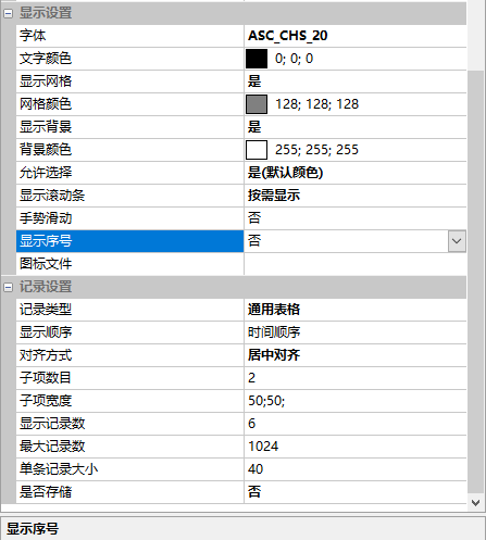
Font
Set the font size and style displayed in the data recording
When using font styles, users need to consider the height value of each row in the table. If the font is set too large and exceeds the height of a row in the table, the text will be "not displayed"
Text color
Set the color displayed by the font
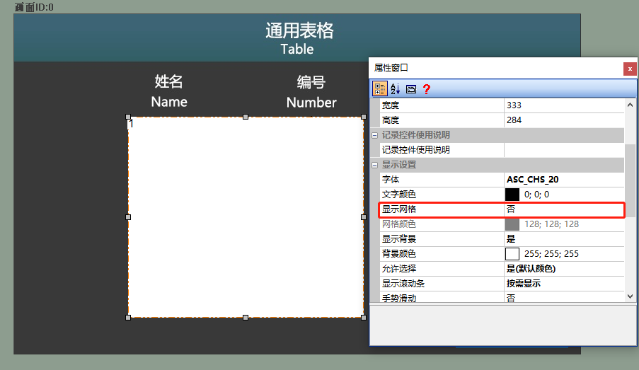
Display Grid
Set grid display, selectable between "Yes" and "No".
[Yes]: Set to "Yes", as shown below
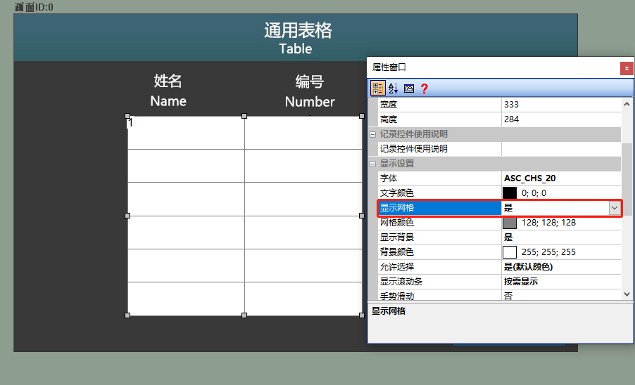
[No]: Set to "No", as shown below
Grid Color
Set the color of the grid display
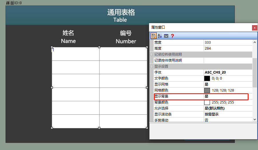
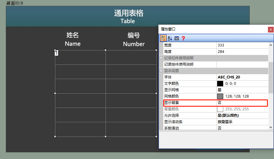
Display Background
Set the display of the background, selectable between "Yes" and "No"
[Yes]: The default background displayed by the control is white, as shown below
[No]: When the background is set to not be displayed, the background content of the screen will be directly displayed, as shown below
Background Color
Set the background color of the table, selectable between "Yes" and "No"
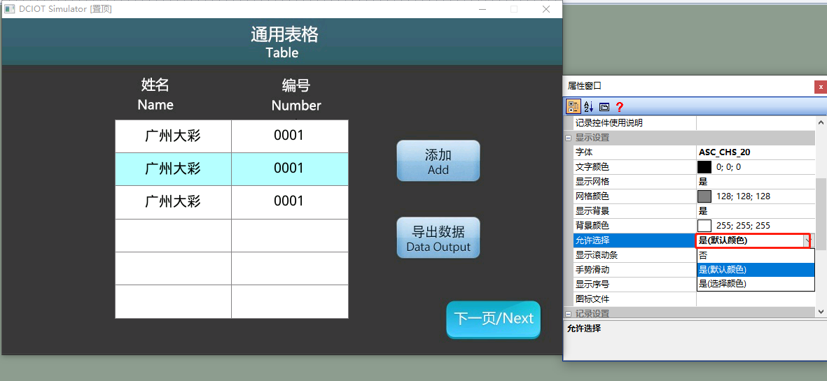
Allow selection
Set to allow selection of the row where the data is located. After running, selecting a sub-item of the data record control will add a background color to the sub-item, as shown below
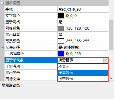
Display scroll bar
Set whether to display the scroll bar status. Options include "Do not display", "Display on demand", or "Fixed display", as shown below
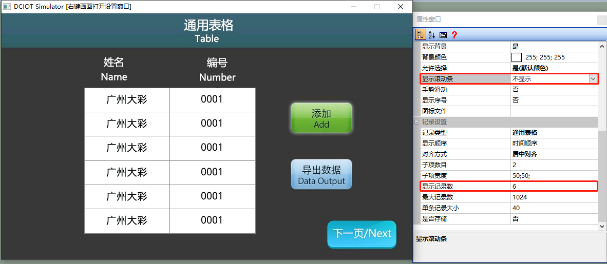
Do not display
When "Display records" is set to "6", if the "Display records" is greater than "6", the first 6 pieces of data will still be displayed, as shown below
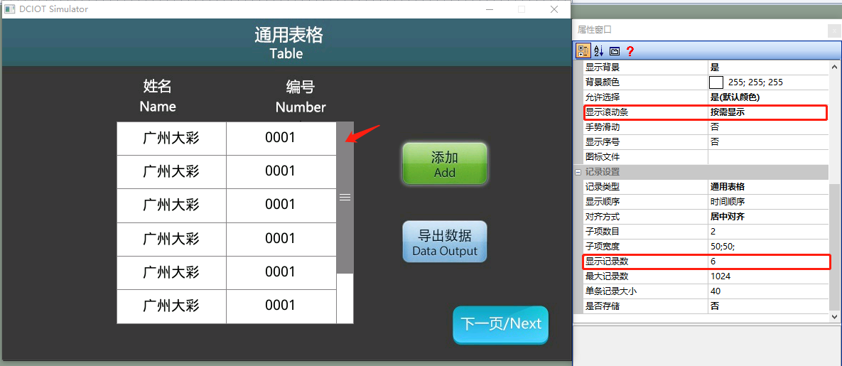
Display on demand
When "Display records" is set to "6", if the number of displayed data is less than "6", the fixed bar will not be displayed; if the number of displayed data is greater than "6", the scroll bar will be displayed and can be dragged to view the data, as shown below
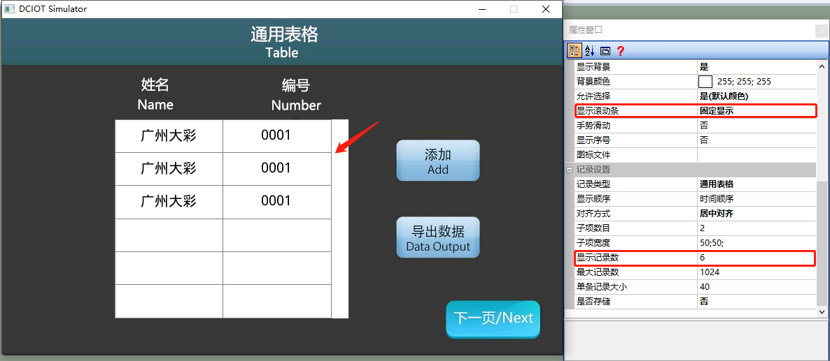
Fixed display
When "Display records" is set to "6", if the number of displayed data is less than "6", the scroll bar box will be displayed; if the number of displayed data is greater than "6", the scroll bar will be displayed in the scroll bar box and can be dragged to view the data, as shown below
Gesture sliding
Set to slide the data record control to view data. Options include "Yes" or "No". When the number of data is greater than the "Display records", clicking and dragging the data record control can view the data
Display Sequence Number
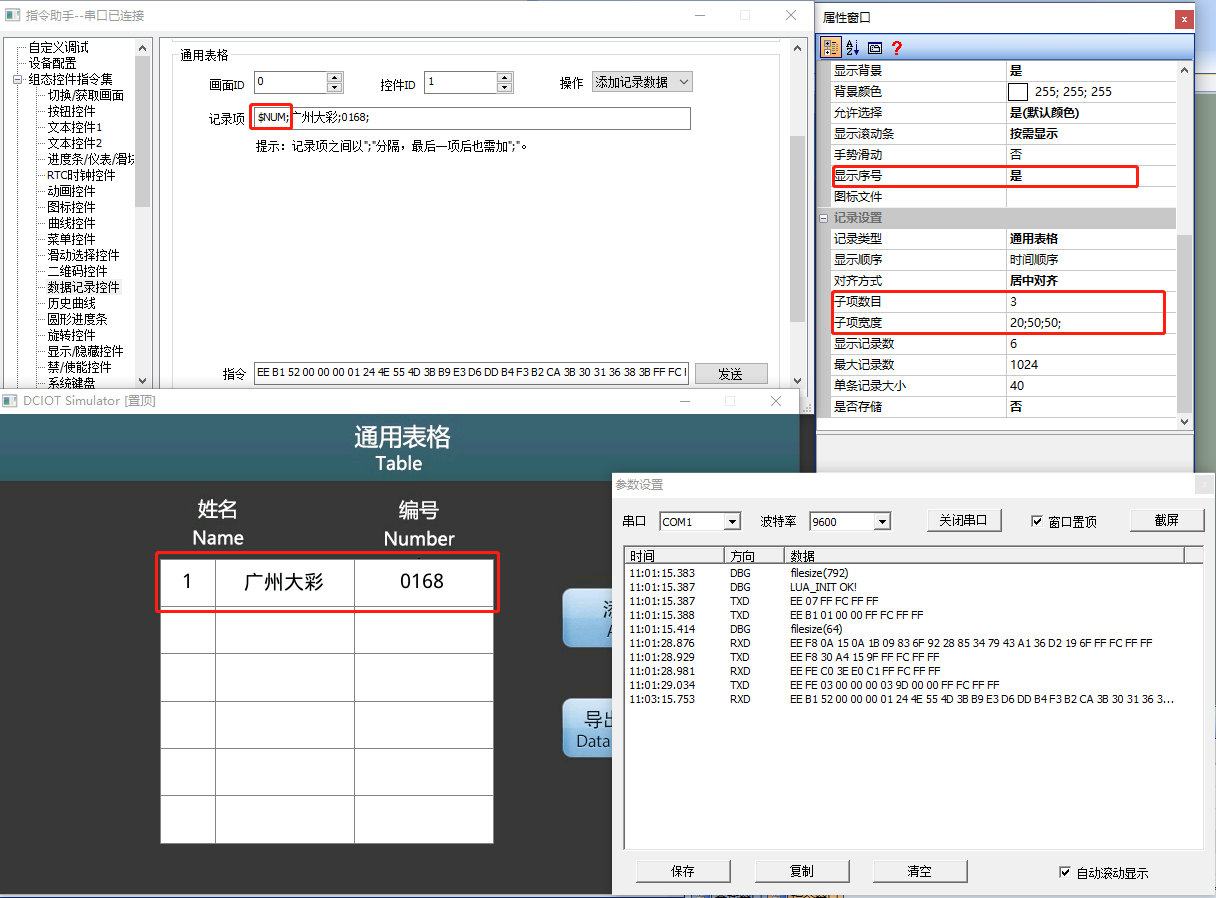
Set the sequence number to be added to each record, with options of "Yes" or "No". This parameter setting takes effect only when the record type is "General Table". The sequence number starts from "1". If you need to display sub-item content in two columns, when adding the sequence number display, you need to set the "Number of Sub-Items" to 3 columns, as shown below
Basic Platform
If you need to display "1 Guangzhou Dacai 0001" on the screen, the data content sent is ";Guangzhou Dacai;0001", and the "Sequence Number" sub-item content is fixed to ";"
F-Type and W-Linked Platform
When setting to add sequence number display, if you need to display "1 Guangzhou Dacai 0168" on the screen, the data content sent is "$NUM;Guangzhou Dacai;0168", and the "Sequence Number" sub-item content is fixed to "$NUM;"
Note: Each sub-item (each column) is separated by the English symbol ";"
Icon File
Set the icon to be added to each record, and you can add the icon path. This parameter setting takes effect only when the record type is "General Table". As shown below
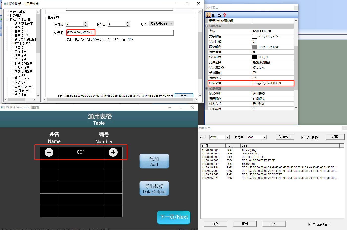
When setting to add icon display, if you need to display the first frame of the icon for the first item (column) and display "001" for the second item, and display the second frame of the icon for the first item (column), the data content sent is "$ICON0;001;$ICON1", and the "Sequence Number" sub-item content is fixed to "$ICONx;" x represents the frame number of the icon file
Note: The size of the set icon should not exceed the height and width of the data record control row, otherwise it may display abnormally or not display at all
Record Type
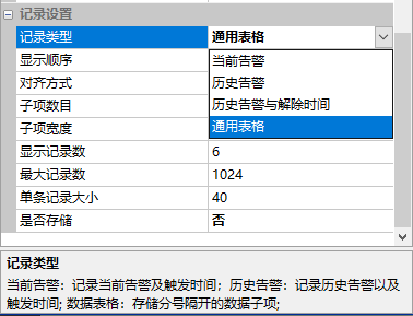
Set different record types, which can be selected as "Current Alarm", "Historical Alarm", "Historical Alarm and Dismissal Time", or "General Table". As shown below
Current Alarm
The number of sub-items is fixed at two (i.e., two columns), with the first item being the alarm event and the second item being the alarm time. When an alarm is generated, the data recording control displays the current alarm and trigger time; when the alarm is dismissed, the data recording control does not display the alarm information. As shown below
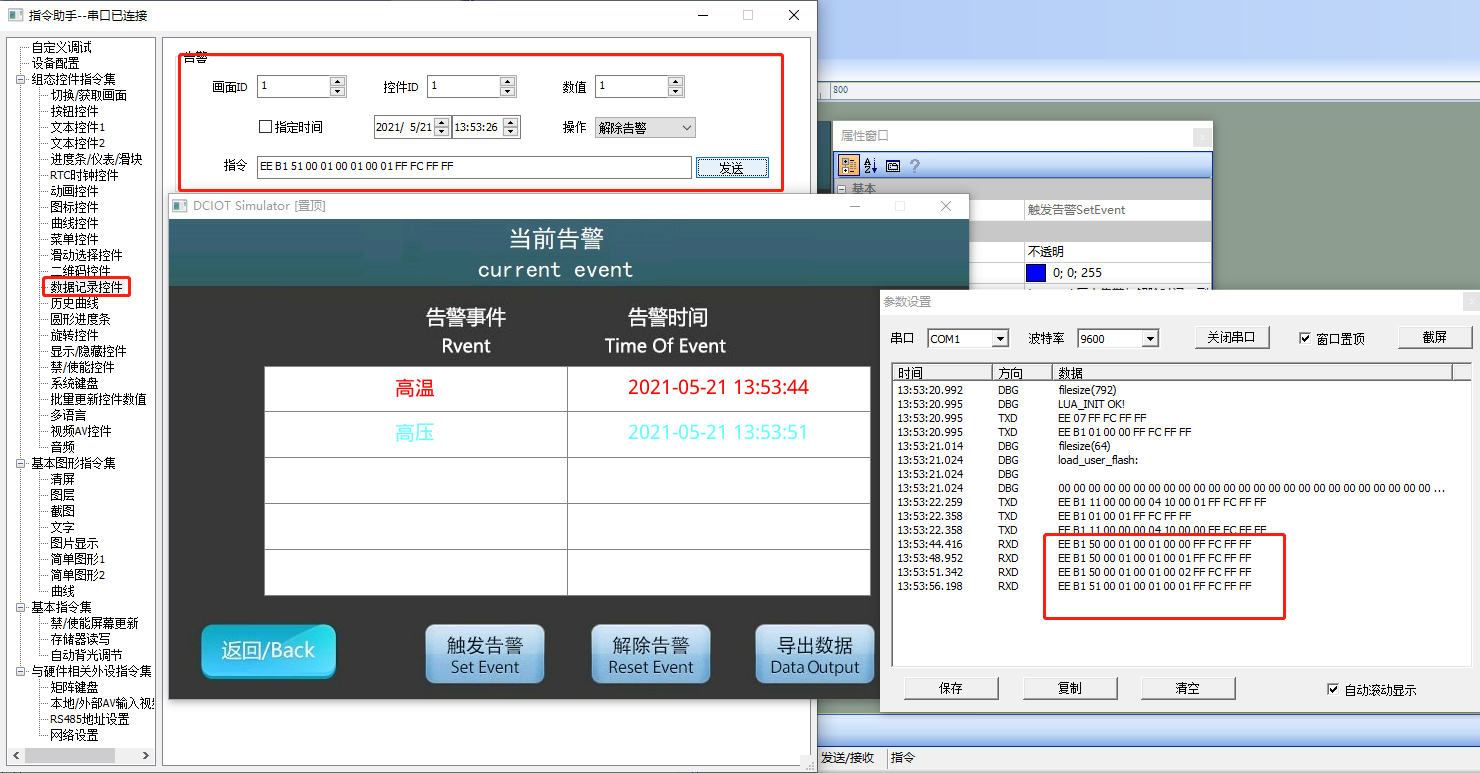
Historical Alarm
The number of sub-items is fixed at two (i.e., two columns), with the first item being the alarm event and the second item being the alarm time. When an alarm is generated, the data recording control displays the alarm and trigger time; when the alarm is dismissed, the alarm data still displays in the table, and past alarm information can be viewed through the scroll bar. As shown below
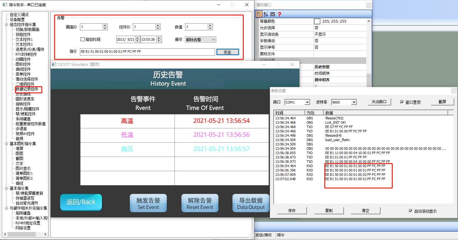
Historical Alarm and Dismissal Time
The number of sub-items is fixed at three (i.e., three columns), with the first item being the alarm event, the second item being the alarm time, and the third item being the dismissal time. When an alarm is generated, the data recording control displays the alarm and trigger time; when the alarm event is dismissed, the dismissal time is displayed, and the alarm data still displays in the table, and past alarm information can be viewed through the scroll bar. As shown below
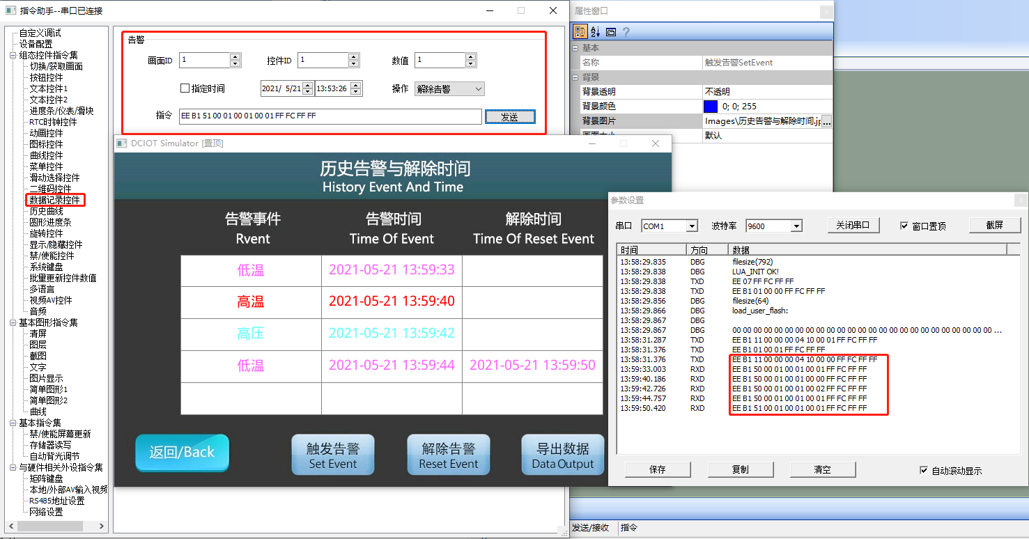
General Table
The number of sub-items is set to two by default (i.e., two columns), and can be set to a maximum of "10" items (columns), which can be used for recording data. The recorded content can be Chinese, letters, or numbers, as shown below
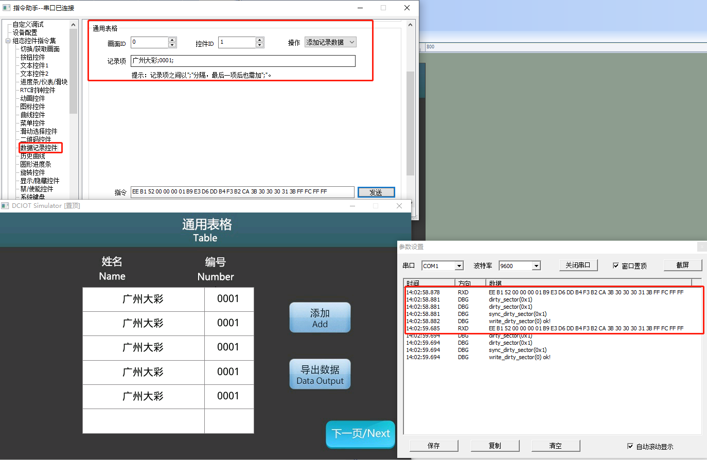
Display Order
Set the display order, which can be selected as "Time Order" or "Time Reverse Order"
Alignment
Set the alignment method for data display, which can be selected as "Left Alignment", "Center Alignment", or "Right Alignment"
Number of Sub-Items
Set the number of sub-items included in each record. This parameter is only valid when the record type is set to "General Table"
Sub-Item Width
Set the width ratio of each sub-item, for example, set to "30;40;50"
Display Record Count
Set the number of records displayed by the control, which is the number of rows displayed. If set to "10", it will display as follows
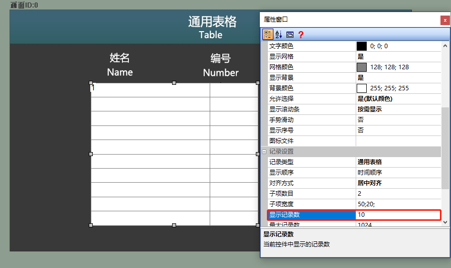
Maximum Record Count
Set the maximum number of records. When full, old records are overwritten. The default is 1024 records
Single Record Size
Set the size of a single record, with a maximum of 256 bytes. This parameter is only valid when the record type is set to "General Table"
Whether to Store
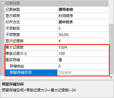
Set whether the recorded data is stored in FLASH (power-off retention), with options of "Yes" or "No". The storage address shares a storage area with the user's 128K storage space, protocol and variable storage, and historical curves.
- Storage Address: Each time a data recording control is placed, the storage address must be reset to avoid overlapping storage addresses.
Reserved Storage Space
The size of the reserved storage space for this "data recording control"
This parameter is automatically calculated by VisualTFT, with reserved storage space = size of a single record * maximum number of records + 24. As shown below, if the size of a single record is "100" bytes and the maximum number of records is 1024, then 102424 bytes need to be reserved for this control.
- Current Alarm: Fixed at 6 bytes, non-changeable, and does not support power-off retention.
- Historical Alarm: Fixed at 6 bytes, non-changeable, and supports power-off retention.
- Historical Alarm and Release Time: Fixed at 10 bytes, non-changeable, and supports power-off retention.
- General Table: Default is 100 bytes, maximum is 256 bytes, depending on the number of data bytes sent by the user's MCU. Supports power-off retention.
Note: The data recording control and historical curve share a storage block. When enabling data storage, the storage address should be set, otherwise data storage and display anomalies may occur.
Data Storage Address Calculation:
Data control storage size = maximum number of records * size of a single record + 24 (unit: bytes)
Historical curve storage size = number of sampling points + 30 (unit: bytes)
Alarm parsing
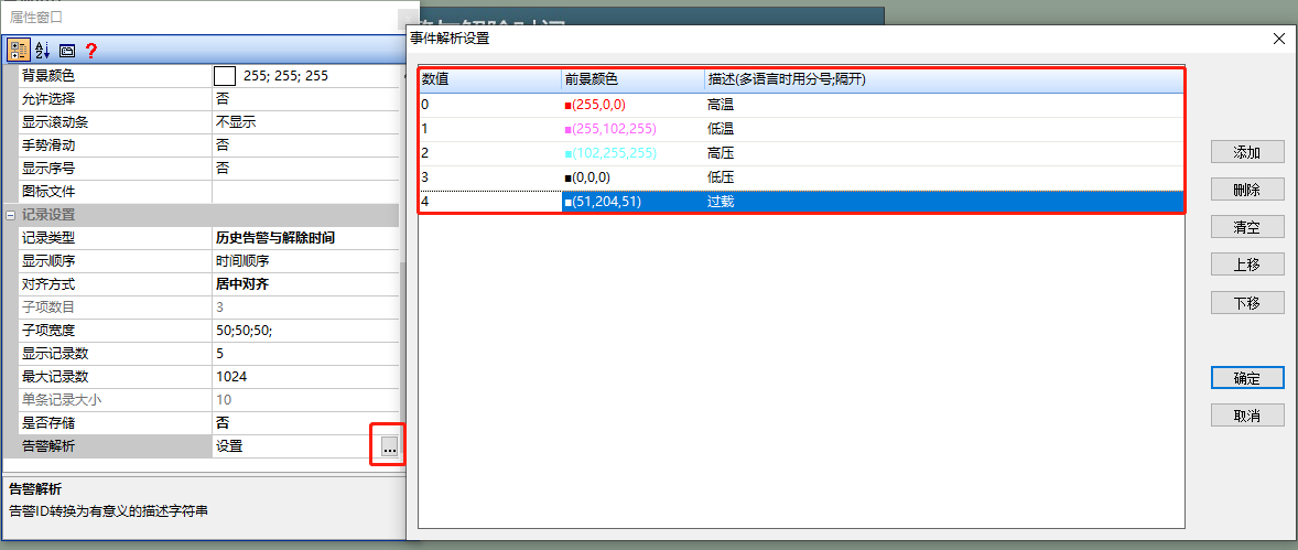
When the record type is "Current Alarm", "Historical Alarm", or "Historical Alarm and Dismiss Time", alarm parsing can be defined. The alarm is displayed in text. If a value of 0 is defined, it is displayed as "High Temperature" in red, as shown below
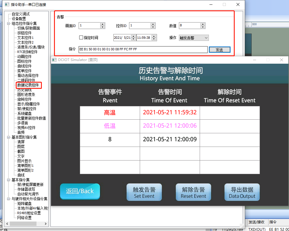
When sending values 0, 1, and 8 to this control, as shown below, the defined values 0 and 1 display the parsed content of the alarm, while the undefined value 8 is still displayed as a numerical value
13.2 General Table
Screen Configuration
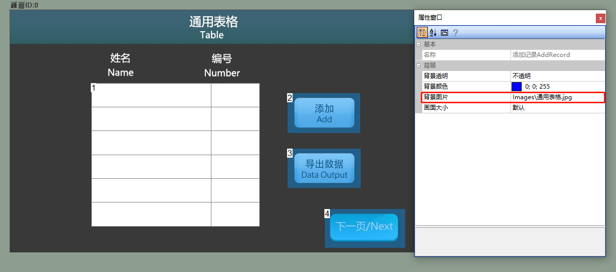
Import the corresponding artwork image in the "Background Image" of the "General Table" screen. Add one data record control (control ID: 1) and three button controls (control IDs: 2-4) to the screen, as shown below
Attribute Configuration
Data Record Control Attributes
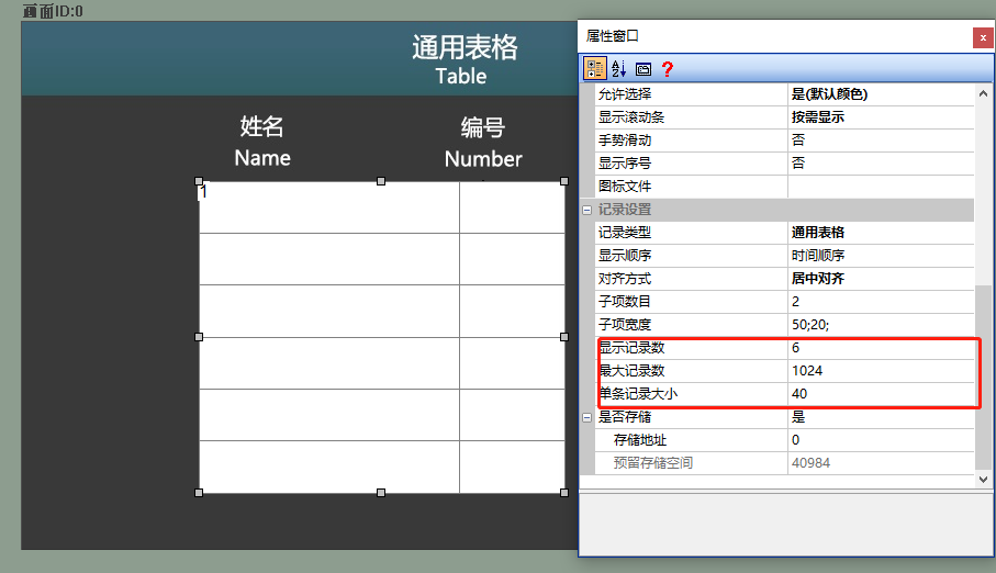
In the attribute window of the data record control, set "Display Record Count" to "6" and "Number of Records per Record" to "40". The attribute configuration is shown below
Add Record Button
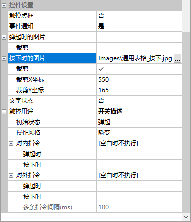
Used to add an alarm record. In the attribute window of the button control (control ID: 2), set "Touch Dotted Box" to "No", "Image when pressed" to the corresponding material path, and "Crop" to "Check". The attribute configuration is shown below
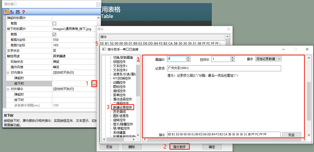
Fill in the internal command for pressing the "Add" button:
- Click on "Internal Command" → "When pressed"
- The command filling box pops up, select "Command Assistant"
- In the Command Assistant interface, select "Data Record Controls" from the left navigation bar
- Set the command parameters in the "Data Record Control" area. As in the example routine, add a record of "Guangzhou Dacai;0001;"
- Copy the command and fill it in the button's internal command, as shown below
Export Data Button
Similarly, the "Export Data" button is used to export CSV files to a USB flash drive or SD card. In the "Internal Commands" section, under "When pressed", find the "2.79 Data Record Control - SD Card Export Command (CSV format)" in the "Jumpy Symbol Serial Port Screen Command Set" document, copy the command, and the command format is as shown below. As in this example, the command is: EE B1 5C 00 00 00 01 FF FC FF FF
| Frame Header | Configuration Command | Function Code - Export to CSV format | Screen ID | Control ID | Frame Tail |
|---|---|---|---|---|---|
| EE | B1 | 5C | 00 00 | 00 01 | FF FC FF FF |
Run Preview
Run the virtual screen, and establish a connection between VisualTFT software and the virtual screen using a "virtual serial port".
On screen control
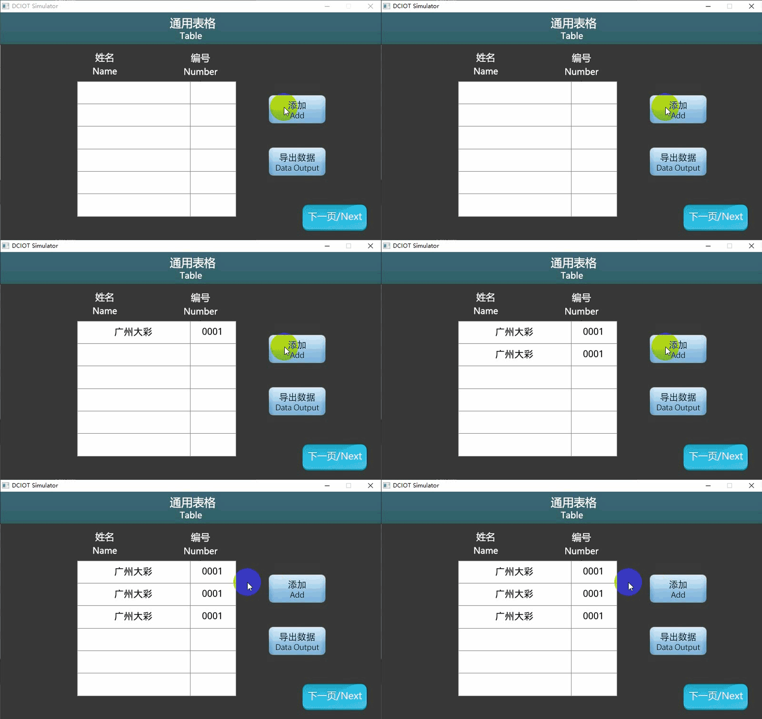
Press the "Add" button, and the first row and column of the data recording control will display "Guangzhou Dacai", and the second column will display "0001". Press the "Add" button again, and the second row of the data recording control will display the same record; When the "Export Data" button is pressed, a CSV file will be displayed in the root directory of the computer's D drive, as shown below
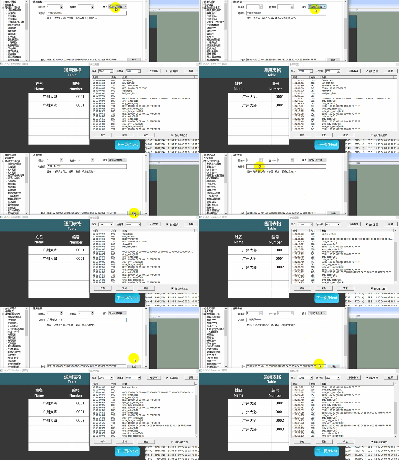
command to add record data
. Select the "Data Record Control" on the left navigation bar and set the command parameters for the "General Table" area. As in the routine, set the data recording control (control ID: 1) in the "General Table" screen, add the recorded data as "Guangzhou Dacai; 0002;" and "Guangzhou Dacai; 0003", click "Send", and the running effect is as follows
Modify a row of record by command
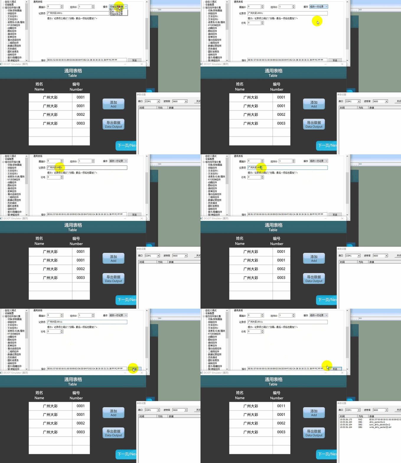
Select "Data Record Control" from the left navigation bar and set the command parameters in the "General Table" area. As in the example routine, modify the number of the first row of data to "0011" and click "Send"; the running effect is shown below
The general table also includes functions such as "Clear Record Data", "Set Position Offset", "Get Record Count", "Read a Row of Record", "Delete a Row of Record", "Insert a Row of Record", "Select a Row of Record", and "Add Multiple Records". Users can experience online debugging through commands and refer to the command set documentation
External MCU Control
For the program of user microcontroller controlling the data record control update, refer to the function declarations in the him.dever.h file and the definitions in the him.dever.c file in the development package Keil program.
Add a Data Record
The code for adding a record is shown below
/**********************************************************************
** Function name: void Record_Add(uint16 screen_id,
**                                uint16 control_id,
**                                uint8 *record);
** Descriptions    :    添加一条数据
** input parameters:    screen_id:     画面ID
**                      control_id:    控件ID
**                      record:    一条记录(字符串),子项通过分号隔开,
**                                 例如:第一项;第二项;第三项;
** output parameters:    无
** Returned value   :    无
*********************************************************************/
{
    ……
    Record_Add (0,1,”广州大彩;0001”);//设置画面0、控件1,第一行显示广州大彩  0001
    ……
}
Modify a Row of Data Record
The code for modifying a row of record is shown below
/**********************************************************************
** Function name:    void Record_Modify(uint16 screen_id,
**                                      uint16 control_id,
**                                      uint8 *record,
**                                      uint16 line_id);
** Descriptions    :    修改一条数据记录
** input parameters:   screen_id:    画面ID
**                          control_id:    控件ID
**                          record:    一条记录(字符串),子项通过分号隔开,
**                                       例如:第一项;第二项;第三项;
**                          line_id    修改的行号
** output parameters:    无
** Returned value:       无
*********************************************************************/
{
    ……
    Record_Modify (0,1,”广州大彩;0088”,1);//修改画面0、控件1,
                                                //第2行数据为“广州大彩;0088”
    ……
}
Export Data Record
The code for exporting to a USB flash drive or SD card in *.csv format is shown below
/**********************************************************************
** Function name:    void Record_Output(uint16 screen_id,
**                                      uint16 control_id);
** Descriptions    :    导出数据记录控件到SD卡,文件格式为CVS
** input parameters:    screen_id :    画面ID
**                      control_id:    控件ID
** output parameters:    无
** Returned value   :    无
*********************************************************************/
{
    ……
    Record_Output (0,1);// 导出画面0、控件1的数据记录控件到SD卡
    ……
}
13.3 Historical Alarms and Release Time
Screen Configuration
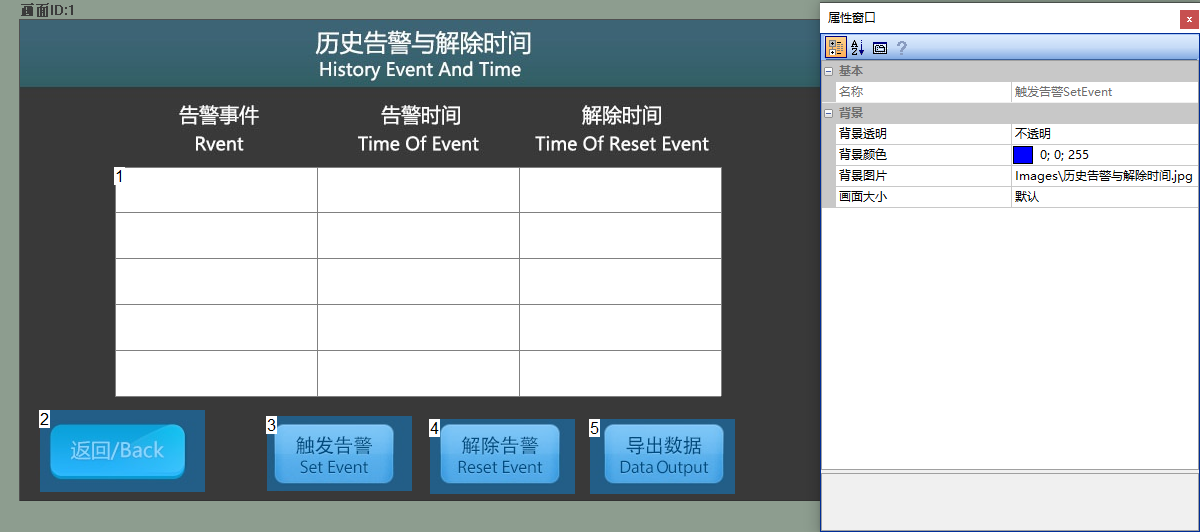
Import the corresponding art design image in the "Background Image" of the "Historical Alarms and Clearance Time" screen, and add one data record control (Control ID: 1) and four button controls (Control IDs: 2-5) to the screen, as shown below
Attribute Configuration
Data Record Control
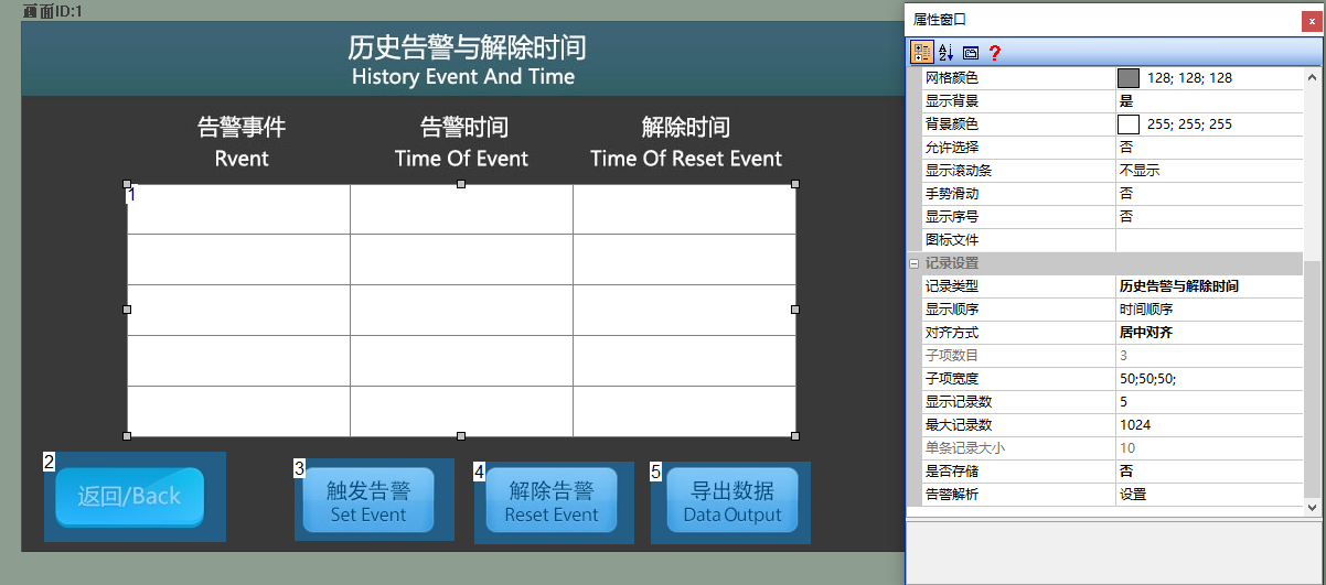
In the attribute window of the data record control, set the "Record Type" to "Historical Alarms and Clearance Time", and set the "Display Record Count" to "5". The attribute configuration is shown below
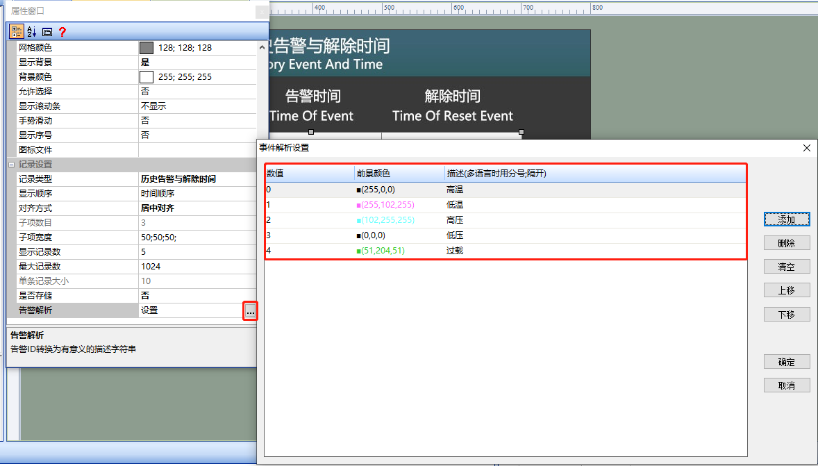
Click on "Alarm Analysis" to display the alarm text, for example: Define value 0 as "High Temperature" with a red color, as shown below. Define the analysis and color for values 1-4 in turn
"Trigger Alarm" Button Control
In the attribute window of the button control (Control ID: 2), set "Touch Dotted Box" to "No", "Image when pressed" to the corresponding material path, and "Crop" to "Check". Fill in "Internal Command" → "When pressed" as "Trigger Alarm Command", as shown below

"Clear Alarm" Button Control
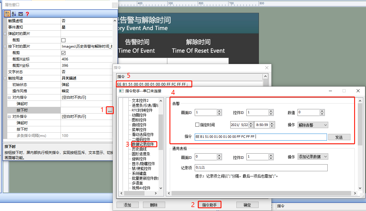
In the attribute window of the button control (Control ID: 3), set "Touch Dotted Box" to "No", "Image when pressed" to the corresponding material path, and "Crop" to "Check". Fill in "Internal Command" → "When pressed" as "Clear Alarm Command", as shown below
"Export Records" Button Control
Refer to "13.2 General Table"
Run Preview
Run Virtual Screen. Establish a connection between VisualTFT software and the virtual screen using "Virtual Serial Port"
On-screen Control
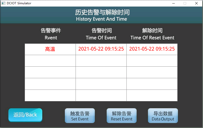
Press the "Trigger Alarm" button. The first line of the data recording control displays "High Temperature and Time" records. Press the "Disarm Alarm" button. The first line of the data recording control displays "Disarm Time". When pressing "Export Data", the file displayed in the root directory of the U-disk/SD is a "CSV file named after the exported RTC time", as shown below
Command to Trigger/Disarm Alarm
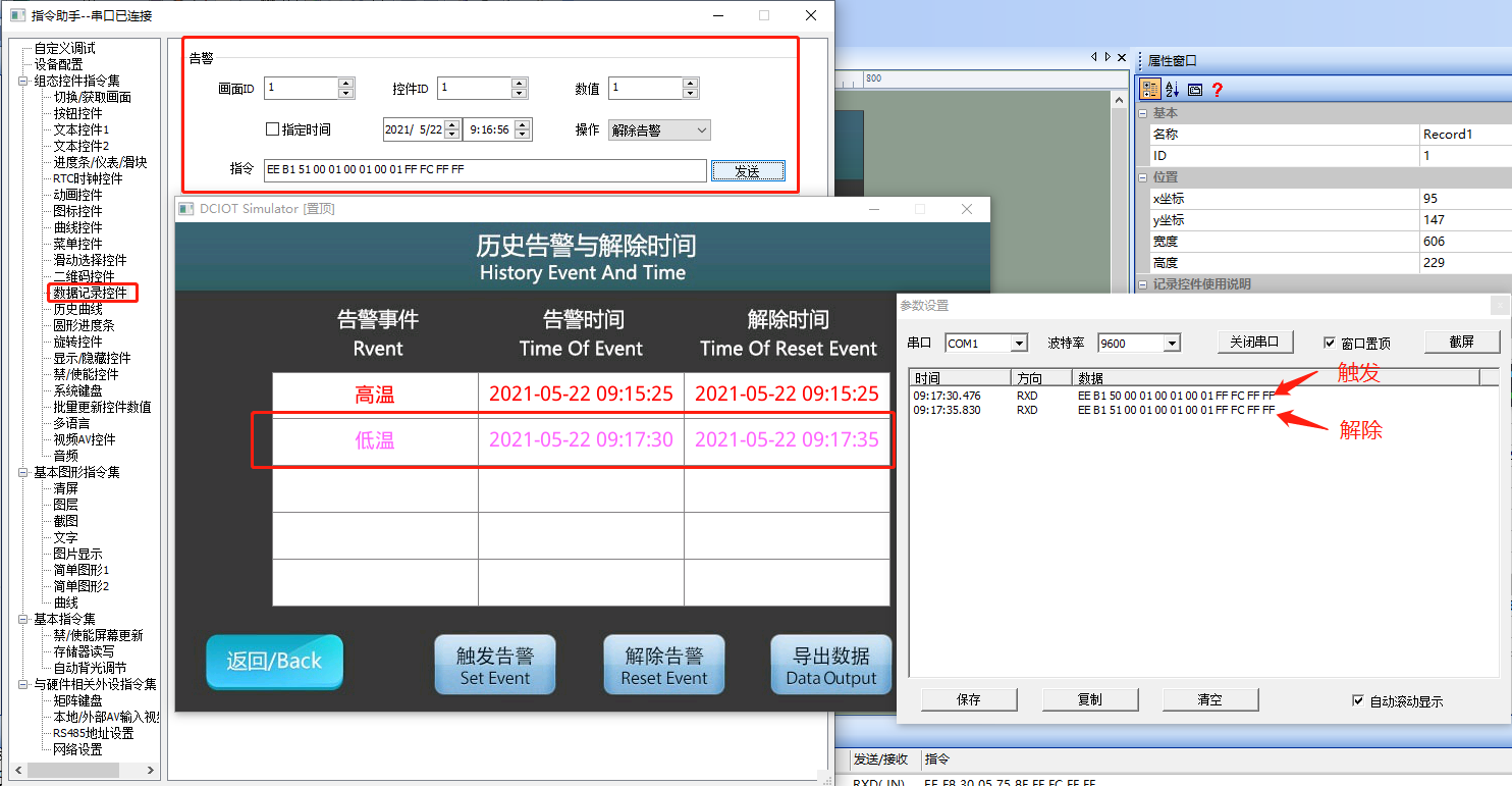
Select "Data Recording Control" from the left navigation bar and set the command parameters in the "Alarm" area. As in the example routine, set the data recording control (control ID: 1) in the "Historical Alarms and Disarm Times" section, trigger an alarm with a trigger value of 1, and click "Send". Then select "Disarm Alarm", as shown below
Single-chip Program
The program for the user's single-chip to control the data recording control. Refer to the function declarations in the him.dever.h file and the definitions in the him.dever.c file in the development package Keil program. The program to trigger an alarm is shown below
/**********************************************************************
** Function name:    Record_SetEvent(uint16 screen_id,
**                                   uint16 control_id,
**                                   uint16 value,
**                                   uint8 *time);
** Descriptions    :     触发警告
** input parameters:     screen_id:  画面ID
**                       control_id:  控件ID
**                       value:  告警值
**                       time:  告警产生的时间,为0时使用屏幕内部时间
** output parameters:    无
** Returned value   :    无
*********************************************************************/
{
    ……
    Record_SetEvent(1,1,0,0);//设置画面1控件1的告警值为0,告警时间为屏的内部时间
    ……
}
The program to disarm an alarm is shown below
/**********************************************************************
** Function name: Record_ResetEvent(uint16 screen_id,
**                                  uint16 control_id,
**                                  uint16 value,
**                                  uint8 *time);
** Descriptions    :    解除警告
** input parameters:    screen_id :    画面ID
**                      control_id:    控件ID
**                      value:  告警值
**                      time : 告警解除的时间,为0时使用屏幕内部时间
** output parameters:   无
** Returned value   :   无
*********************************************************************/
{
  ……
  Record_ResetEvent (1,1,0,0);// 设置画面1控件1的告警值为0
                              // 解除时间为屏的内部时间
  ……
}

Leave a Reply