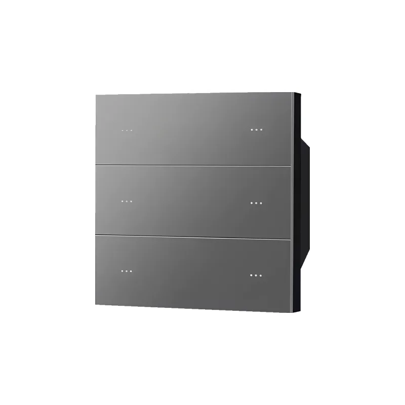
1. Product Overview
485 intelligent panel is an industrial grade control terminal based on RS485 bus, supporting dual versions of weak current (DC12/24V) and strong current (AC220V), suitable for smart home, industrial automation, building control and other scenarios. The core functions include:
- Button customization instructionSupports ASCII string/hexadecimal instructions, multi action triggering (press/release/long press), and cyclic sending of two sets of instructions.
- Flexible Control: Independently manage backlight, button indicator lights, and 4-channel relays.
- Dual Protocol Support: Compatible with standard Modbus RTU and manufacturer defined protocols.
- Remote Management: Modify parameters, upgrade firmware, and debug devices through software configuration.
II. Product Specifications
1. Hardware Type
| Project | Weak current panel | Strong current panel |
|---|---|---|
| Power supply | DC12/24V | AC220V |
| Relay | No (requires external actuator) | 4-channel independent relay output |
| Wiring terminal | VCC, A, B, GND | L/N (power supply), A/B (485), L1-L4 (relay) |
| Communication interface | RS485 (A/B line) | RS485 (A/B line) |
2. Technical Parameters
| project | parameter |
|---|---|
| Address Range | 1-42 (0x01~0x2A), broadcast address 0xFF |
| Default parameters for serial port | Baud rate 9600, 8 data bits, 1 stop bit, no checksum |
| Custom Storage | NR-X9P: 256 bytes; NR-SWRS series: 512 bytes |
| instruction delay | Unified delay (global) or independent delay (per instruction) |
3, Installation and wiring
1. Wiring of weak current panel
- Terminal Definition:
VCC(Positive pole of power supply)GND(Power Ground)A(RS485 A line)B(RS485 B line). - Wiring steps:
- Connect VCC/GND to DC12/24V power supply.
- A/B is connected to the RS485 bus.
2. Strong current panel wiring
- Terminal Definition:
L/N: Connect AC220V live/neutral wire.A/B: Connected to RS485 bus.L1-L4: 4-channel relay output (connected to load).- Wiring steps:
- Connect L/N to an AC220V power supply.
- A/B is connected to the RS485 bus.
- L1-L4 is connected to load equipment (such as lamps, motors).
IV. Function Configuration
1. Address Setting
- Software Modification:
- Connect the panel to the computer using a USB to 485 cable.
- Open the "Smart Panel" software, select the serial port number and start.
- Enter the current address ->click "modify" ->enter a new address ->save.
Note: When the address is unknown, it can be modified by broadcasting the address
0xFF.
- Manual modification:
- Press and hold the setting button for 5 seconds to enter the setting mode (indicator light flashes).
- Press the settings key to increase the address value (automatically saved each time you press).
- Automatically exits after 5 seconds of inactivity.
- Restore default: In the setting mode, press and hold the setting key again for 5 seconds to restore the address to
0x01.
2. Work mode setting
through the register0x1003Configuration:
| Position | Function | Description |
|---|---|---|
| Bit9 | Protocol Selection | 0: Manufacturer Protocol;1: Standard Modbus RTU |
| Bit8 | Key Sending Protocol | 0: Modbus format;1: Custom Data |
| Bit5 | Release button to actively send | 1: Enable;0: Prohibit |
| Bit3 | Backlight Delay Extinguish | 1: Extinguish after 10 seconds without operation;0: Always on |
| Bit2 | Press the button to actively send | 1: Enable;0: Prohibit (Host Polling) |
| Bit0 | Demo mode | 1: Key control backlight/relay;0: Normal Mode |
Configuration Example:
正常模式+主动发送+背光延时熄灭 → 01 06 10 03 02 14 7C 65V. Detailed Explanation of Core Functions
1. Button Custom Instructions
Supports 4 Action Trigger Instructions:Press, Short Press Release, Long Press, Long Press Release.
- Instruction Type:
- ASCII string(e.g.
"开灯n",nis a carriage return). - Hexadecimal(such as
01 06 10 31 00 01 1D 05). - Advanced Function:
- Loop Sending: Two sets of instructions are triggered alternately (first press send group 1, then press send group 2 again).
- Delay Control:
- Unified Delay: All instruction intervals are the same (global setting).
- Independent Delay: Set the delay independently after each instruction (e.g. 50ms → 100ms → 150ms).
- Extra Long Instruction: A single action can span multiple storage spaces (up to 512 bytes).
Configuration steps:
- Open the "Parameter Configuration. exe" software and connect to the panel.
- Select button → Check action type → Enter instruction content → Set delay → Save.
2. Backlight and indicator light control
- Unified control register (
0x1008: Simultaneously control the backlight and 8 button lights.
所有背光亮+按键1灯亮 → 01 06 10 08 01 01 CC 98- Independent Control:
- Backlight: Register
0x1020(1lights up,0goes out). - Button light: Register
0x1021~0x1028(buttons 1-8, supports2flip state).
3. Relay Control
- Unified Control Register (
0x100A: Simultaneously controls 4 relays (Bit0~Bit3 correspond to relays 1~4).
继电器1导通 → 01 06 10 0A 00 01 6C C8- Independent control: Register
0x1031~0x1034(relays 1-4, supporting2flip state).
VI. Protocol Docking
1. Standard Modbus RTU Protocol
- Host Read Button Status:
  发送:01 03 13 10 00 08 41 4D
返回:01 03 10 00 00 00 00 00 ...(16字节状态数据)- Button Active Reporting(Enable Bit2/Bit5):
按键按下:01 03 00 02 02 02 64 AB // 绝对键值=(地址-1)*6+按键号2. Manufacturer Protocol
- Data Length Field is2 bytes(Standard Modbus is 1 byte), all other formats are the same.
7. Debugging and Maintenance
1. Real time Debugging
By configuring the software:
- Monitor button status (active/passive mode).
- Manual control of backlight/relay.
- Send custom command test.
2. Serial port parameter settings
onlyNR-SWRS seriesSupport:
- Baud rate: 300~115200
- Parity: None/Odd/Even
- Configuration method: Select parameters in the software → click "Write".
3. Firmware Upgrade
- Click on "Device Search" → Select Target Panel.
- Click on "Firmware Upgrade" ->select the. bin firmware file.
- Check "Restore default parameters" (optional) → Start upgrade.
Note: If the upgrade fails, please retry. After success, it is recommended to restore the factory settings.
4. Factory Reset
- Software Operation: Click "Factory Reset" → Device will automatically restart.
- Effect: Address, parameters, and protocol all return to default values.
VIII. Appendix
1. Version Update Record
| Version | Date | Update Content |
|---|---|---|
| V1.0 | 2023-08-22 | Initial Version Release |
| V1.1 | 2024-01-31 | 1. Added custom button sending 2. Supports standard Modbus 3. Firmware upgrade function |
| V1.2 | 2024-12-14 | 1. Instruction delay setting 2. Two sets of instruction loop sending 3. Supports ultra long instructions 4. Serial port parameter setting |


Leave a Reply