
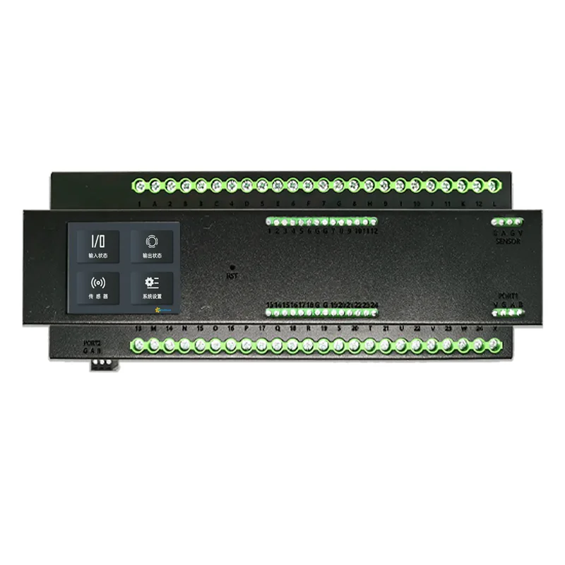
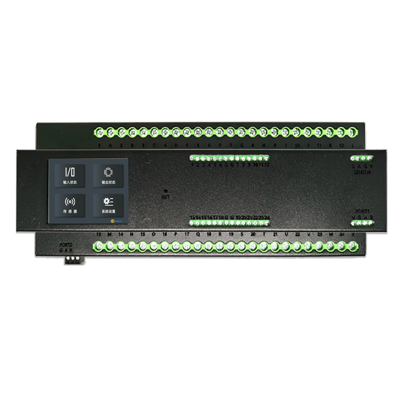
Product Description
M24162 is a multifunctional 24 circuit intelligent relay module with 16A self holding relay and LCD touch display. It has DI input function and sensor access function, two 485 ports, and port 2 can choose multiple communication connections (RS485/RS232/LORAMESH/4GCAT1/NET) for external communication. It supports standard Modbus Rtu/Modbus Tcp communication protocol.
Product purchase:https://www.modbus.cn/product/31033.html
Selection Suggestions
is widely applicable to various scenarios where the switch power is not high enough, such as homes, office buildings, hotels, banks, hospitals, schools, airports, museums, laboratories, factories, etc. It can also be used as a common spare part for professionals such as building integrators and smart home solution engineers to solve unexpected problems on site.
Product Parameters
- Product Name:24 Channel Relay Module
- Product Model:M24162
- Inductive Load:5A
- Resistive Load:10A
- Shell Material:Sheet Metal Spray Metal Shell
- 2.4-inch Screen: Resolution: 240 *320
- Relay: 16A Self Holding Non Heating
- Product Size:228* 85 * 57mm
- Product Weight:1.15kg
- Input voltage:DC12V
- Communication protocol:Modbus RTU
- Baud rateDefault 9600 8N1 (modifiable)
- Input circuit:24 channel DI (optocoupler isolation)
- Installation method:Installation of DN35 guide rail
- Port 1:485
- Port 2:Standard 485, optional RS232/LORA MESH/4GCAT1/NET
- Sensor:Support optional carbon monoxide/temperature and humidity/in body counting/lighting
Product Features
- 1. Adopting Hongfa's high-quality 16A self-sustaining non heating relay
- 2. All 24 DI inputs adopt optocoupler isolation input circuit
- 3. The appearance of the side should be consistent with the standard air opening shape, and the guide rail should be installed.
- 4. Equipped with a color touch LCD screen, easy and simple on-site operation and configuration
- 5. Port 1 comes standard with 485, while Port 2 offers optional communication with RS232/LORA MESH/4G CAT1/NET.
- 6. Both IO support dual register reading, support 01/02/05 coil reading and writing function codes, and also support 03/06/10 function code reading and writing. 7. Supports multiple communication baud rates and can be directly modified through the touch screen.
- 7. Supports multiple communication baud rates and can be directly modified through the touch screen.
- 8. Comes with 4 sensors (carbon monoxide, temperature and humidity, human counting, lighting) linked together, and the output of the linked relay can be configured through the touch screen.
- 9, Sheet metal spray painted metal shell, and 5.08 large terminal independent terminal post.
- 10. The touch screen supports multiple languages in Chinese and English, with standard Modbus protocol.
Screen operation
① Local color screen intelligent processing:The device's built-in 2.4-inch screen can display the input and output status of 24 circuits in real time, and the linkage of input and output can be set through the screen.
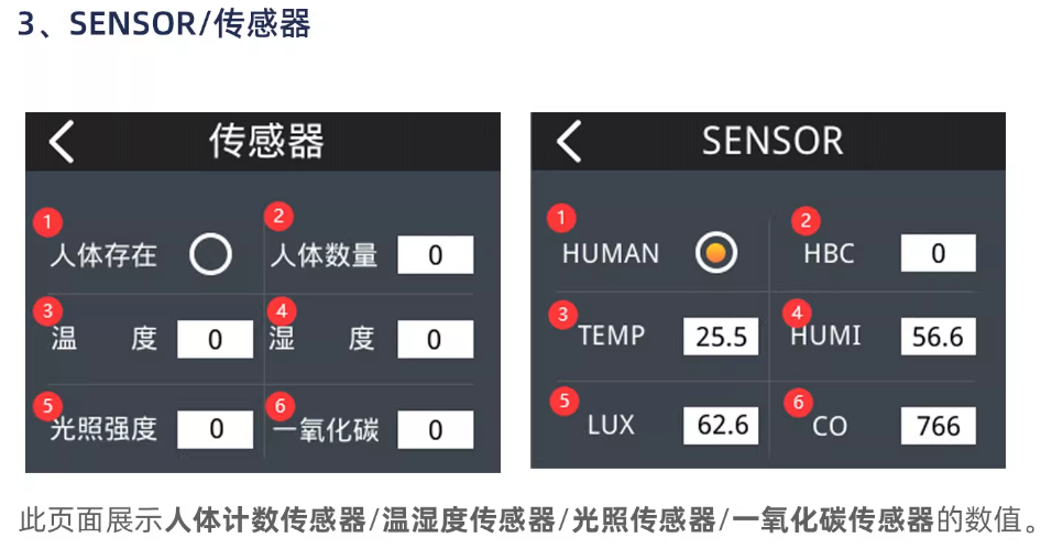
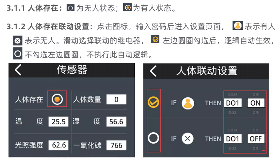
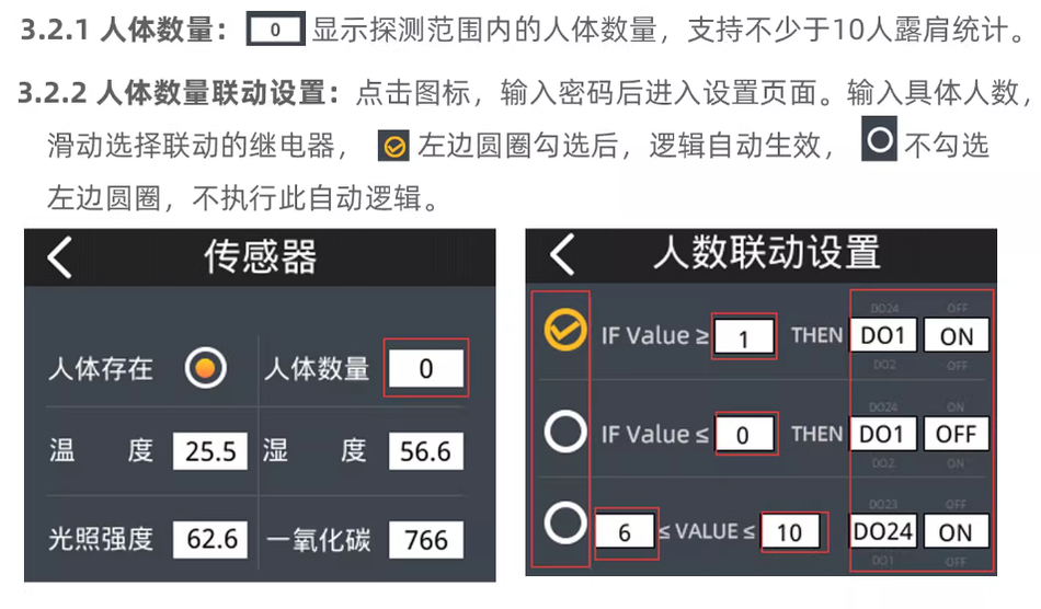
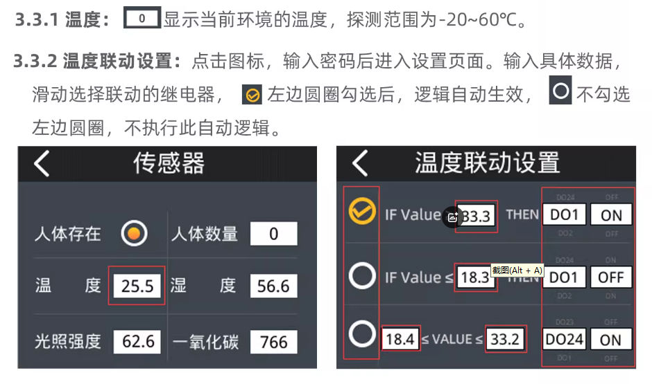
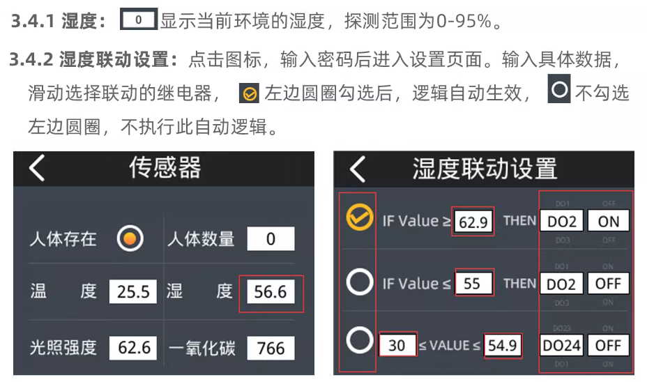
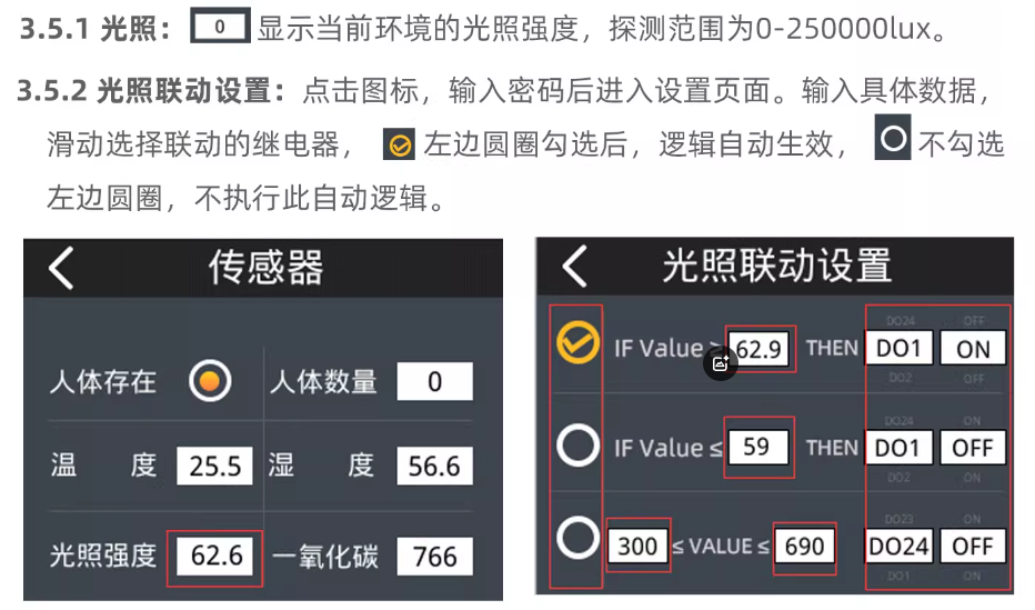
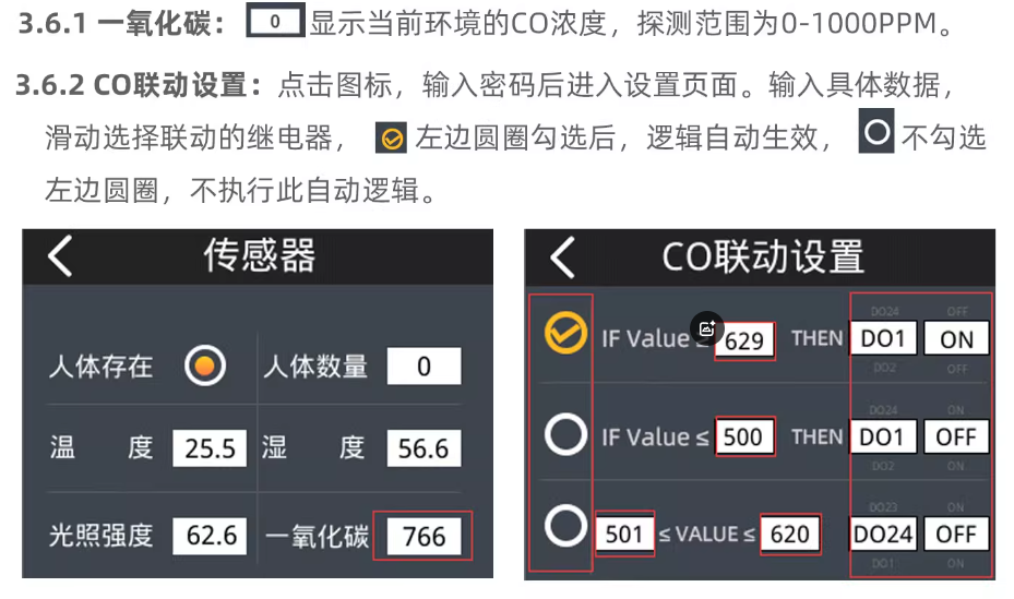
② External sensors:Supports the integration of external human counting sensors, temperature and humidity sensors, lighting sensors, and carbon monoxide sensors. Through a color screen automation system, real-time collection and intelligent response of sensor data are achieved.
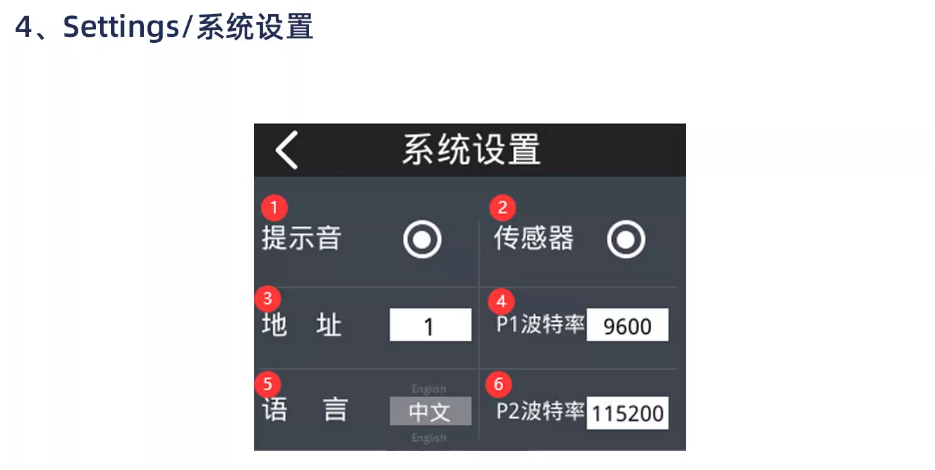
③ Multi language switching:The system language supports switching between Chinese and English,
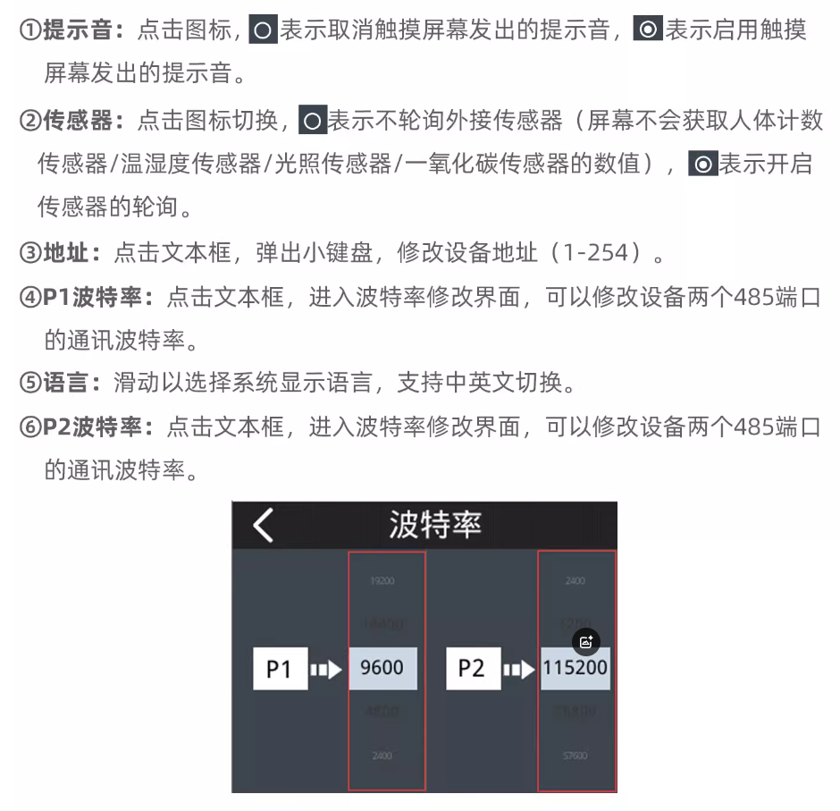
④ Baud rate modification:Directly modify the baud rate of two 485 ports through the local color screen, making the operation more convenient.
⑤ Device Address Modification:Modifying device address through local color screen makes the operation more convenient.
* 24 independent high-power 16A relay, supporting 24 digital signal input detection, real-time data display and parameter configuration through local color touch screen, without relying on the cloud, directly setting values, delay actions, linkage strategies through the screen, suitable for intelligent room management, production line equipment control, building automation and other application scenarios.
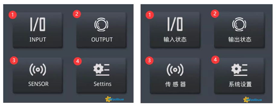
① INPUT/Input Status:Click to enter the "24 Input Status Display Page"
② OUTPUT/Output Status:Click to enter the "24 Output Status Display Page"
③ Sensor/Sensor:Click to enter the "Sensor Status/Numerical Display Page"
④ Settings/System Settings:Click to enter the system settings.
Setting Guide
1. INPUT/Input Status
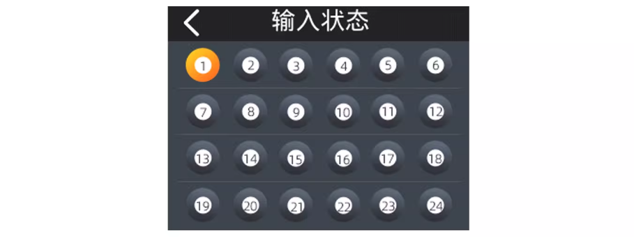
① This page displays the status of 24 DIs. When a DI is connected, the corresponding icon's outer circle is displayed in yellow; When DI is disconnected, the outer circle of the corresponding icon is displayed in black.
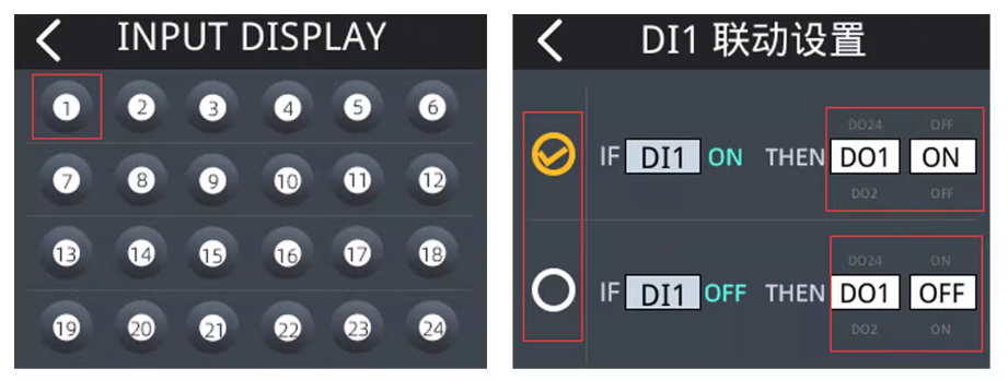
② Click on the corresponding icon, enter the password, and enter the DI linkage settings page. After sliding and selecting the left circle of the linked relay, this logic will automatically take effect. If the left circle is not selected, this automatic logic will not be executed.
2. OUTPUT/Output Status
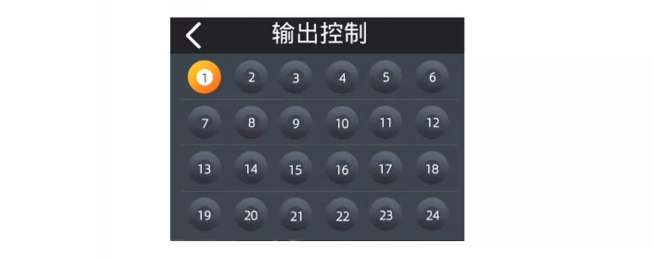
① This page displays the status of 24 relays D0. When the relay is turned on, the outer circle of the corresponding icon displays yellow. When the relay is turned off, the outer circle of the corresponding icon displays black.
Communication Protocol
| Register Address Memory Mask | |||||||
| Function Code FUNCTION | Register Name NAME | Read/Write R/W | Register Address Decimal Register Add (DEC) | register address hexadecimal Register Add (HEX) | Value Value | Value meaning Value meaning | Remark Remarks |
| 03 Read Holding Registers (4x) ____________ 06 Write single register | Address address | Read/Write | 0000 | 0x0000 | 00 01 | Address Range 01-FE Address range 01-FE | |
| Port2- Baud Rate | Read/Write | 0001 | 0x0001 | 00 06 | 00-115200 Baud 01-76800 Baud 02-57600 Baud 03-38400 Baud 04-19200 Baud 05-14400 Baud 06-9600 Baud 07-4800 Baud 08-2400 Baud 09-1200 Baud | ||
| INTER(no change) | Read/Write | 0002 | 0x0002 | no change | no change | no change | |
| Port1 Baud Rate | Read/Write | 0003 | 0x0003 | 00 06 | 00-115200 Baud 01-76800 Baud 02-57600 Baud 03-38400 Baud 04——19200 Baud 05——14400 Baud 06——9600 Baud 07——4800 Baud 08——2400 Baud 09——1200 Baud | ||
| 03 Read Holding Registers (4x) ____________ 06 Write single register | OUTPUT1 | R/W | 0016 | 0x0010 | 00 01 | 00: close 01: OPen | |
| OUTPUT2 | R/W | 0017 | 0x0011 | 00 01 | 00: close 01: OPen | ||
| OUTPUT3 | R/W | 0018 | 0x0012 | 00 01 | 00: close 01: OPen | ||
| OUTPUT4 | R/W | 0019 | 0x0013 | 00 01 | 00: close 01: OPen | ||
| OUTPUT5 | R/W | 0020 | 0x0014 | 00 01 | 00: close 01: OPen | ||
| OUTPUT6 | R/W | 0021 | 0x0015 | 00 01 | 00: close 01: OPen | ||
| OUTPUT7 | R/W | 0022 | 0x0016 | 00 01 | 00: close 01: OPen | ||
| OUTPUT8 | R/W | 0023 | 0x0017 | 00 01 | 00: close 01: OPen | ||
| OUTPUT9 | R/W | 0024 | 0x0018 | 00 01 | 00: close 01: OPen | ||
| OUTPUT10 | R/W | 0025 | 0x0019 | 00 01 | 00: close 01: OPen | ||
| OUTPUT11 | R/W | 0026 | 0x001A | 00 01 | 00: close 01: OPen | ||
| OUTPUT12 | R/W | 0027 | 0x001B | 00 01 | 00: close 01: OPen | ||
| OUTPUT13 | R/W | 0028 | 0x001C | 00 01 | 00: close 01: OPen | ||
| OUTPUT14 | R/W | 0029 | 0x001D | 00 01 | 00: close 01: OPen | ||
| OUTPUT15 | R/W | 0030 | 0x001E | 00 01 | 00: close 01: OPen | ||
| OUTPUT16 | R/W | 0031 | 0x001F | 00 01 | 00: close 01: OPen | ||
| OUTPUT17 | R/W | 0032 | 0x0020 | 00 01 | 00: close 01: OPen | ||
| OUTPUT18 | R/W | 0033 | 0x0021 | 00 01 | 00: close 01: OPen | ||
| OUTPUT19 | R/W | 0034 | 0x0022 | 00 01 | 00: close 01: OPen | ||
| OUTPUT20 | R/W | 0035 | 0x0023 | 00 01 | 00: close 01: OPen | ||
| OUTPUT21 | R/W | 0036 | 0x0024 | 00 01 | 00: close 01: OPen | ||
| OUTPUT22 | R/W | 0037 | 0x0025 | 00 01 | 00: close 01: OPen | ||
| OUTPUT23 | R/W | 0038 | 0x0026 | 00 01 | 00: close 01: OPen | ||
| OUTPUT24 | R/W | 0039 | 0x0027 | 00 01 | 00: close 01: OPen | ||
| 03 Read Holding Registers (4x) | Input1 | R | 0041 | 0x0029 | 00 00 | 00: close 01: OPen | |
| Input2 | R | 0042 | 0x002A | 00 00 | 00: close 01: OPen | ||
| Input3 | R | 0043 | 0x002B | 00 00 | 00: close 01: OPen | ||
| Input4 | R | 0044 | 0x002C | 00 00 | 00: close 01: OPen | ||
| Input5 | R | 0045 | 0x002D | 00 00 | 00: close 01: OPen | ||
| Input6 | R | 0046 | 0x002E | 00 00 | 00: close 01: OPen | ||
| Input7 | R | 0047 | 0x002F | 00 00 | 00: close 01: OPen | ||
| Input8 | R | 0048 | 0x0030 | 00 00 | 00: close 01: OPen | ||
| Input9 | R | 0049 | 0x0031 | 00 00 | 00: close 01: OPen | ||
| Input10 | R | 0050 | 0x0032 | 00 00 | 00: close 01: OPen | ||
| Input11 | R | 0051 | 0x0033 | 00 00 | 00: close 01: OPen | ||
| Input12 | R | 0052 | 0x0034 | 00 00 | 00: close 01: OPen | ||
| Input13 | R | 0053 | 0x0035 | 00 00 | 00: close 01: OPen | ||
| Input14 | R | 0054 | 0x0036 | 00 00 | 00: close 01: OPen | ||
| Input15 | R | 0055 | 0x0037 | 00 00 | 00: close 01: OPen | ||
| Input16 | R | 0056 | 0x0038 | 00 00 | 00: close 01: OPen | ||
| Input17 | R | 0057 | 0x0039 | 00 00 | 00: close 01: OPen | ||
| Input18 | R | 0058 | 0x003A | 00 00 | 00: close 01: OPen | ||
| Input19 | R | 0059 | 0x003B | 00 00 | 00: close 01: OPen | ||
| Input20 | R | 0060 | 0x003C | 00 00 | 00: close 01: OPen | ||
| Input21 | R | 0061 | 0x003D | 00 00 | 00: close 01: OPen | ||
| Input22 | R | 0062 | 0x003E | 00 00 | 00: close 01: OPen | ||
| Input23 | R | 0063 | 0x003F | 00 00 | 00: close 01: OPen | ||
| Input24 | R | 0064 | 0x0040 | 00 00 | 00: close 01: OPen | ||
| 03 Read Holding Registers (4x) | TEMP | R | 0100 | 0x0064 | 00 00 | temperature | The device address is fixed at 01 range:-20~60℃ |
| HUMI | R | 0101 | 0x0065 | 00 00 | Humidity | The device address is fixed at 01 range:0~95% | |
| CO | R | 0102 | 0x0066 | 00 00 | CO concentration | The device address is fixed at 02 range:0-1000PPM | |
| LUX-HI | R | 0103 | 0x0067 | 00 00 | LUX-HI: High bit register LUX Lo: Low Bit Register Light intensity calculation formula: Lux=(illuminance data Hl * 65536+illuminance data Lo)/100 Then: Lux=(0 * 65536+6960)/100=69.6 (lux) | The device address is fixed at 03 range:0~250000lux | |
| LUX-Lo | 0104 | 0x0068 | 00 00 | ||||
| Human existence | R | 0105 | 0x0069 | 00 00 | 00: nobady 01: somebody | The device address is fixed at 04 Human Presence | |
| Human Body Count | R | 0106 | 0x006A | 00 00 | Number of detected human bodies | The device address is fixed at 04 Number of detected human bodies | |
01 Read Coils (0x) —————— 05 Write Single Coil | OUTPUT1 | R/W | 0000 | 0x0000 | 00 00 | 00: close 01: OPen | |
| OUTPUT2 | R/W | 0001 | 0x0001 | 00 00 | 00: close 01: OPen | ||
| OUTPUT3 | R/W | 0002 | 0x0002 | 00 00 | 00: close 01: OPen | ||
| OUTPUT4 | R/W | 0003 | 0x0003 | 00 00 | 00: close 01: OPen | ||
| OUTPUT5 | R/W | 0004 | 0x0004 | 00 00 | 00: close 01: OPen | ||
| OUTPUT6 | R/W | 0005 | 0x0005 | 00 00 | 00: close 01: OPen | ||
| OUTPUT7 | R/W | 0006 | 0x0006 | 00 00 | 00: close 01: OPen | ||
| OUTPUT8 | R/W | 0007 | 0x0007 | 00 00 | 00: close 01: OPen | ||
| OUTPUT9 | R/W | 0008 | 0x0008 | 00 00 | 00: close 01: OPen | ||
| OUTPUT10 | R/W | 0009 | 0x0009 | 00 00 | 00: close 01: OPen | ||
| OUTPUT11 | R/W | 0010 | 0x000A | 00 00 | 00: close 01: OPen | ||
| OUTPUT12 | R/W | 0011 | 0x000B | 00 00 | 00: close 01: OPen | ||
| OUTPUT13 | R/W | 0012 | 0x000C | 00 00 | 00: close 01: OPen | ||
| OUTPUT14 | R/W | 0013 | 0x000D | 00 00 | 00: close 01: OPen | ||
| OUTPUT15 | R/W | 0014 | 0x000E | 00 00 | 00: close 01: OPen | ||
| OUTPUT16 | R/W | 0015 | 0x000F | 00 00 | 00: close 01: OPen | ||
| OUTPUT17 | R/W | 0016 | 0x0010 | 00 00 | 00: close 01: OPen | ||
| OUTPUT18 | R/W | 0017 | 0x0011 | 00 00 | 00: close 01: OPen | ||
| OUTPUT19 | R/W | 0018 | 0x0012 | 00 00 | 00: close 01: OPen | ||
| OUTPUT20 | R/W | 0019 | 0x0013 | 00 00 | 00: close 01: OPen | ||
| OUTPUT21 | R/W | 0020 | 0x0014 | 00 00 | 00: close 01: OPen | ||
| OUTPUT22 | R/W | 0021 | 0x0015 | 00 00 | 00: close 01: OPen | ||
| OUTPUT23 | R/W | 0022 | 0x0016 | 00 00 | 00: close 01: OPen | ||
| OUTPUT24 | R/W | 0023 | 0x0017 | 00 00 | 00: close 01: OPen | ||
| 02 Read Discrete Inputs (1x) | Input1 | R | 0000 | 0x0000 | 00 00 | 00: close 01: OPen | |
| Input2 | R | 0001 | 0x0001 | 00 00 | 00: close 01: OPen | ||
| Input3 | R | 0002 | 0x0002 | 00 00 | 00: close 01: OPen | ||
| Input4 | R | 0003 | 0x0003 | 00 00 | 00: close 01: OPen | ||
| Input5 | R | 0004 | 0x0004 | 00 00 | 00: close 01: OPen | ||
| Input6 | R | 0005 | 0x0005 | 00 00 | 00: close 01: OPen | ||
| Input7 | R | 0006 | 0x0006 | 00 00 | 00: close 01: OPen | ||
| Input8 | R | 0007 | 0x0007 | 00 00 | 00: close 01: OPen | ||
| Input9 | R | 0008 | 0x0008 | 00 00 | 00: close 01: OPen | ||
| Input10 | R | 0009 | 0x0009 | 00 00 | 00: close 01: OPen | ||
| Input11 | R | 0010 | 0x000A | 00 00 | 00: close 01: OPen | ||
| Input12 | R | 0011 | 0x000B | 00 00 | 00: close 01: OPen | ||
| Input13 | R | 0012 | 0x000C | 00 00 | 00: close 01: OPen | ||
| Input14 | R | 0013 | 0x000D | 00 00 | 00: close 01: OPen | ||
| Input15 | R | 0014 | 0x000E | 00 00 | 00: close 01: OPen | ||
| Input16 | R | 0015 | 0x000F | 00 00 | 00: close 01: OPen | ||
| Input17 | R | 0016 | 0x0010 | 00 00 | 00: close 01: OPen | ||
| Input18 | R | 0017 | 0x0011 | 00 00 | 00: close 01: OPen | ||
| Input19 | R | 0018 | 0x0012 | 00 00 | 00: close 01: OPen | ||
| Input20 | R | 0019 | 0x0013 | 00 00 | 00: close 01: OPen | ||
| Input21 | R | 0020 | 0x0014 | 00 00 | 00: close 01: OPen | ||
| Input22 | R | 0021 | 0x0015 | 00 00 | 00: close 01: OPen | ||
| Input23 | R | 0022 | 0x0016 | 00 00 | 00: close 01: OPen | ||
| Input24 | R | 0023 | 0x0017 | 00 00 | 00: close 01: OPen | ||


Leave a Reply