

I. Introduction to the tutorial case
This case will demonstrate how to configure theNA111 serial port server to access the ModBus IoT platform, enabling the ModBus IoT platform to collect DI status and control DO output of the MA01-AXCX4020 device.

II. Relationship diagram
Relationship diagram of the NA111 serial port server and MA01-AXCX4020 connected to the ModBus IoT platform:

III. Preparation for the serial port server device
One NA111 serial port server;
One MA01-AXCX4020 serial port IO networking module;
One network cable;
RS485Several communication cables;
Two 12V switching power supplies;
IV. ModBus IoT Platform
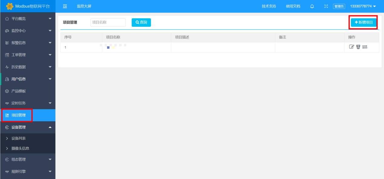
1. Create a project, fill in the corresponding information in the new project, and save it, as shown in the figure:
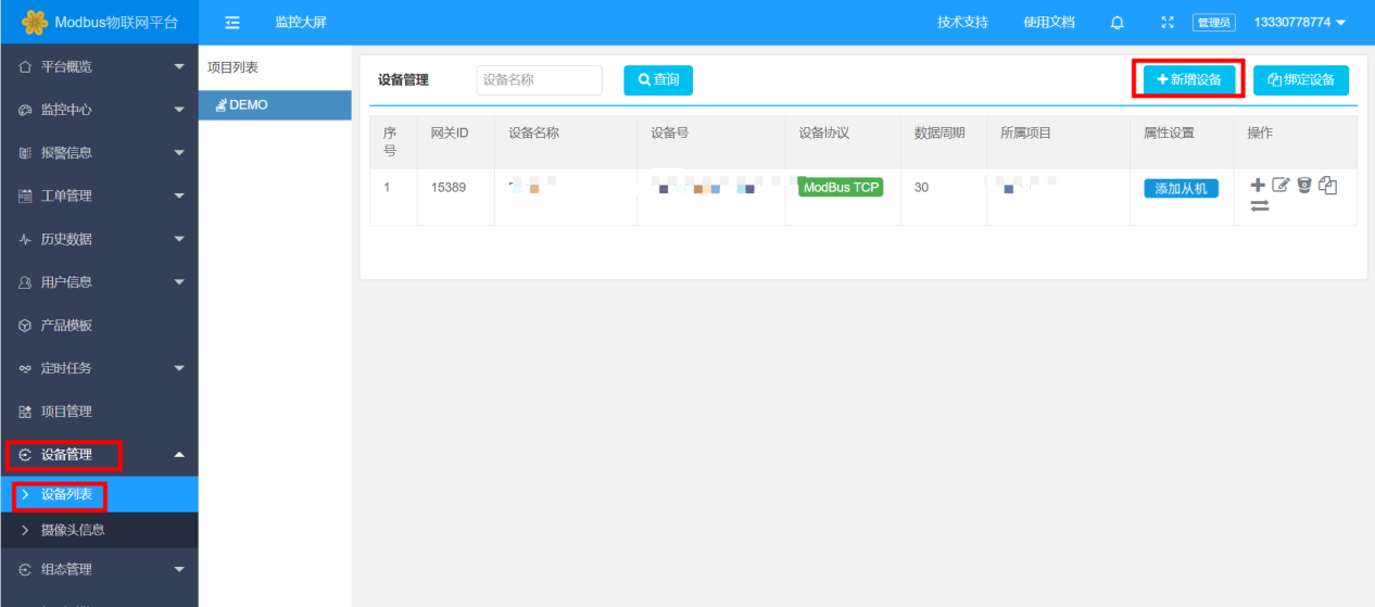
2. Create a device. Click on the device list in Device Management to add a new device, as shown in the figure:
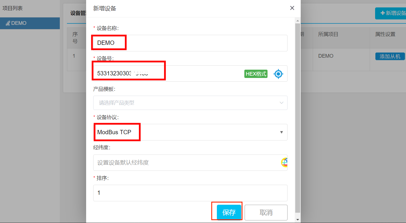
3. Fill in the device name, either manually (customized) or randomly generate a device number SN (copy the device number SN for backup). Select ModBus TCP in the device protocol, and leave the other fields blank. Then save it, as shown in the figure:
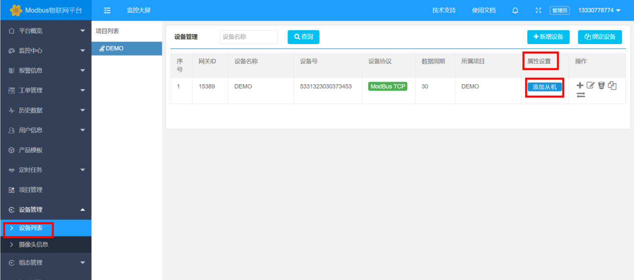
4. Add the RS-485 connected MA01-AXCX4020 device. Find theserial port serverdevice just created in the device list. Then in the property settings, click to add a slave device, as shown in the figure:
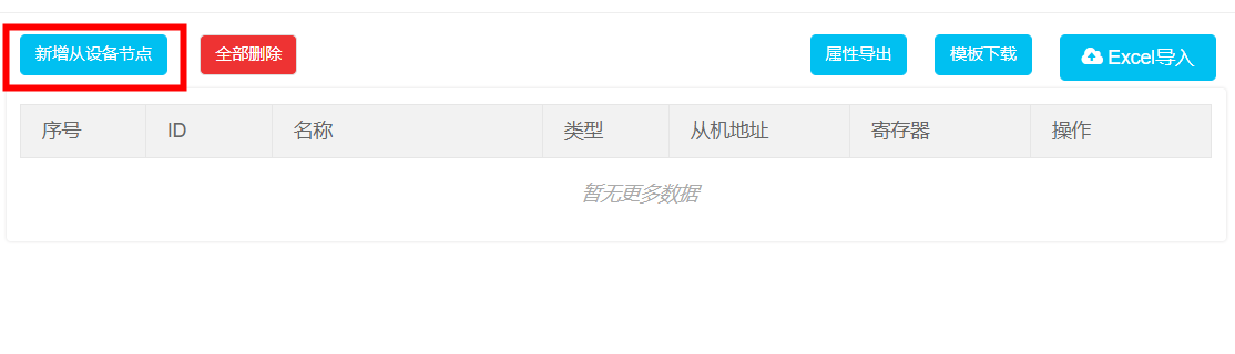
5. After a dialog box pops up, click to add a new slave device node, as shown in the figure:
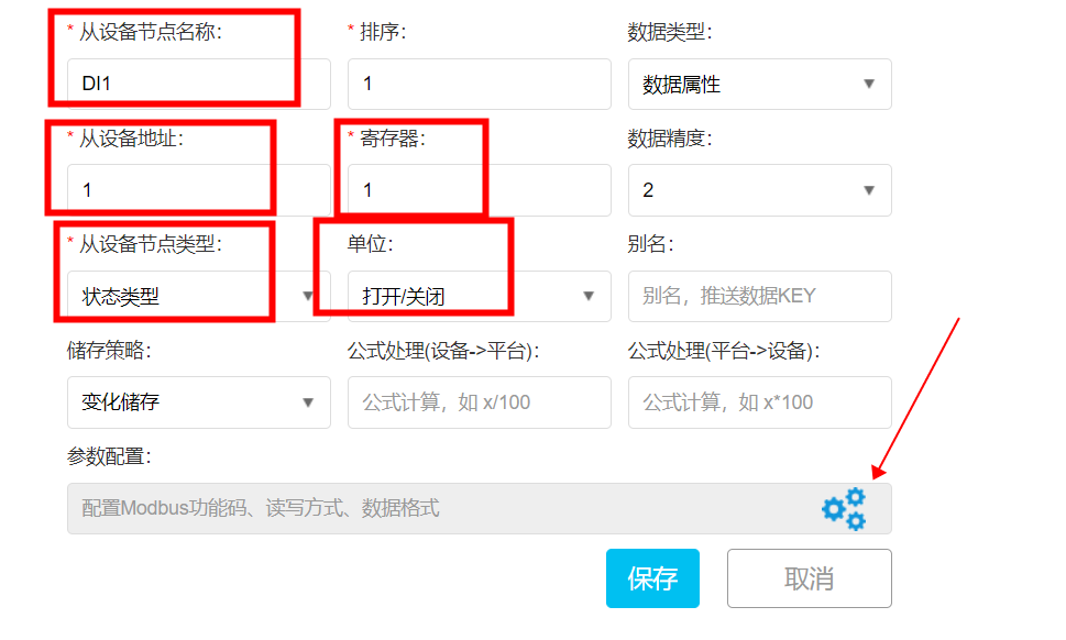
6. Add a DI channel, with slave name: DI1, slave address: 1 (corresponding to the device address of MA01-AXCX4020), register: 1 (corresponding to the register address of DI1 of MA01-AXCX4020), slave node type selection: status type, unit selection: open/close. Finally, click the icon for parameter configuration, as shown in the figure:
Note: To query the hardware register addresses of the MA01-AXCX4020 device, download the user manual from the product details on the Ebyte official website (https://www.ebyte.com) to find the register addresses.
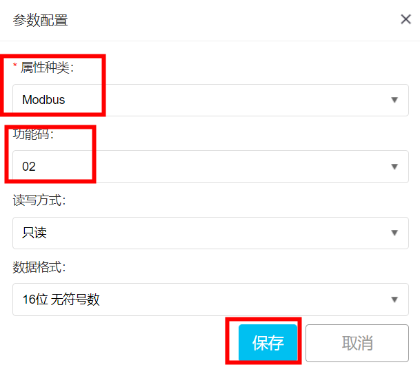
7. In the pop-up parameter configuration dialog box, select ModBus for attribute type and 02 for function code, and then click "Save", as shown in the figure:
8. Finally, click "Save" to configure one DI channel, as shown in the figure:
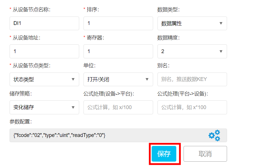
After saving, it will be as shown in the figure:

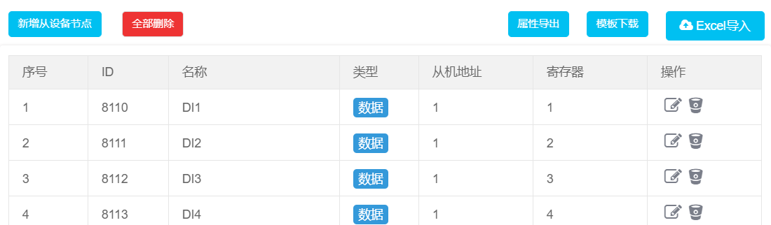
9. Add four DI channels in sequence, only needing to modify the register address, as shown in the figure:
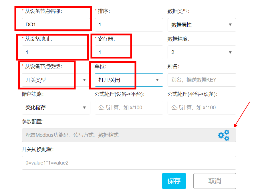
10. Add one DO channel, with node name: DO1, device address: 1 (corresponding to the device address of MA01-AXCX4020), register: 1 (corresponding to the register address of DO1 in MA01-AXCX4020), node type: switch type, unit: open/close, and finally click the icon for parameter configuration, as shown in the figure:
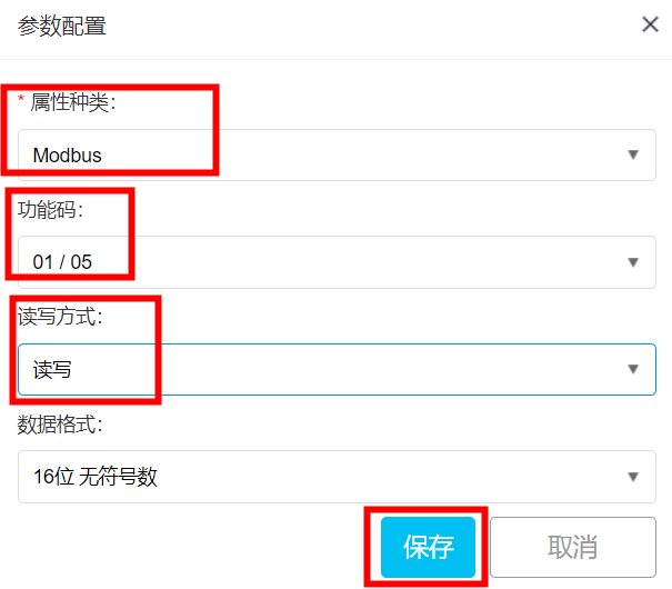
11. In the pop-up parameter configuration dialog box, select ModBus for attribute type, 01/05 for function code, and read-write mode for read-write mode, and then click "Save", as shown in the figure:
12. Add two DO channels in sequence, only needing to modify the register address, as shown in the figure:

13. This completes the configuration of all data points for MA01-AXCX4020.
V. NA111 Serial Server Configuration
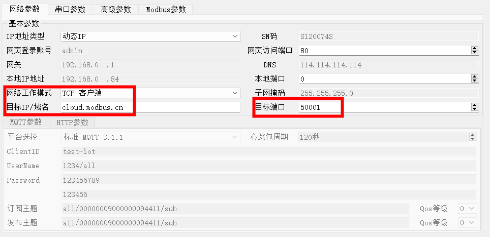
1. Open the upper computer ofNA111 Serial Server(available for download from the corresponding location on the Ebyte official website) to configure network parameters, changing the network working mode to TCP client, target IP/domain name: cloud.ModBus.cn, target port: 50001 (ModBus)Connection parameters of the IoT platform, as shown in the figure:
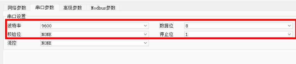
2. Click on Serial Port Parameters and configure the serial port parameters as: 9600-8N1 (consistent with the MA01-AXCX4020 serial port parameter configuration, so the configuration of MA01-AXCX4020 serial port parameters will not be further described), as shown in the figure:
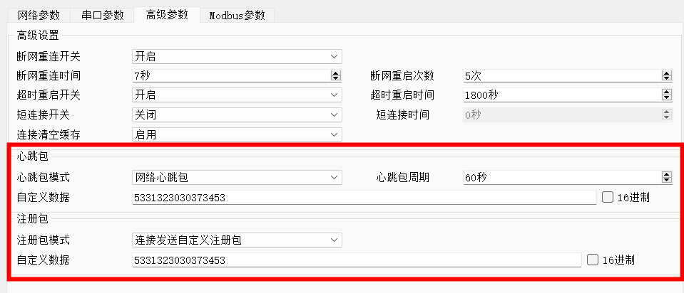
3. Click on Advanced Parameters and configure the heartbeat packet mode as: Network Heartbeat Packet, heartbeat cycle: 60 seconds, and fill in the custom data of the heartbeat packet with the device number SN backed up in the cloud platform: 5331323030373453; configure the registration packet mode as: Send Custom Registration Packet on Connection, and fill in the custom data of the registration packet with the device number SN backed up in the cloud platform: 5331323030373453, as shown in the figure:
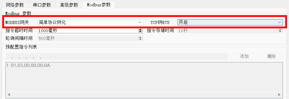
4. Click on ModBus Parameters and turn on theSimple Protocol Conversionfunction of the ModBus gateway, and enable TCP to RTU conversion, as shown in the figure:
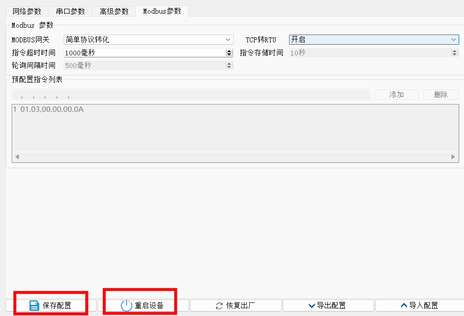
5. After completing all configurations, click on Save Configuration, and after saving, restart the device, as shown in the figure:
VI. Function Demonstration
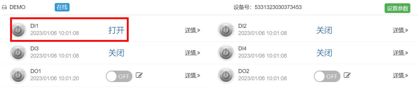
1. Collect DI Status: Change the status of DI1 of the MA01-AXCX4020 device, and the ModBus IoT platform will collect the status of DI1 of the MA01-AXCX4020 device through the NA111 serial port server, as shown in the figure:
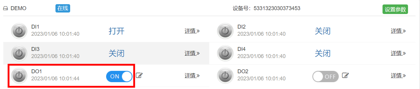
2. Control DO Output: The ModBus IoT platform issues an open command and controls the status of DO1 of the MA01-AXCX4020 device through the NA111 serial port server, as shown in the figure:
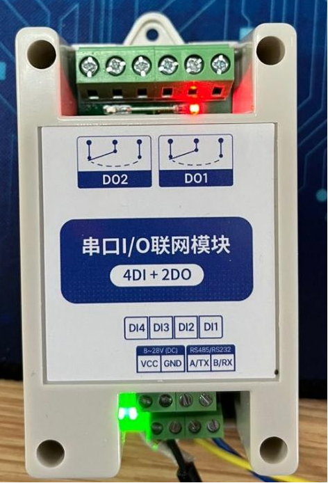
Thus, the ModBus IoT platform is implemented throughSerial port servercollects DI status and controls DO output of MA01-AXCX4020 device.
Article source: https://baijiahao.baidu.com/s?id=1757064560035187477&wfr=spider&for=pc


Leave a Reply