
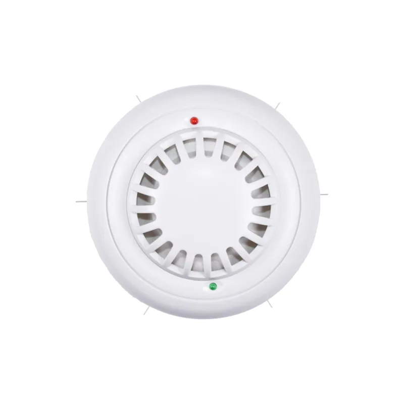
JT-S1603B adopts the industrial universal standard RS485 bus MODBUS-RTU protocol interface, which facilitates the integration of various instruments or systems such as PLC and DCS for monitoring smoke status variables. Internally, high-precision sensing cores and related components are used to ensure high reliability and excellent long-term stability of the product. Multiple output modes such as RS232, CAN, Lora, WIFI, GPRS, NB-IOT can be customized.
Read the baud rate encoding of the current device. Baud rate encoding: 1 is 2400; 2 is 4800; 3 is 9600; 4 is 19200; 5 is 38400; 6 is 115200.
1, Add anti reverse protection for sensor power supply, Industrial site surge protection.
2, The product is equipped with a high decibel buzzer alarm and LED LED light prompt
3, RS485 Communication interface, Asynchronous half duplex mode, Support secondary development.
4, Communication baud rate 2400, 4800, 9600, 19200, 38400, 115200bp s Can be set,
The factory default value is 9600 bp s.
5, Has a wide measurement range, High precision, Good linearity, Good universality.
6, RS485(MODBUT-RTU Multi sensor networking communication protocol, 1200 Meter long distance transmission. 7, The ceiling mounted circular shell is easy to use, Easy to install.
8, The shell adopts ABS Flame retardant material, High temperature resistance, Not easily corroded, Not easily deformed.
Technical parameters
| Smoke measurement range | 0~2000PPM |
| Maximum allowable error for smoke | ±7% |
| Error in smoke repeatability testing | ±5% |
| Smoke sensitive body | Thermally responsive semiconductor |
| Communication interface | RS485 (MODBUT-RTU) |
| Default baud rate | 9600(Default)8,n,1 |
| Power supply | DC12~24V |
| Display resolution | 1PPM |
| power waste | ≤0.1W |
| Operating environment | -30~80℃,0~100RH%(No anti condensation measures) |
| External dimensions |
Product selection
The product has been designed RS485, 4~20MA, DC0~5V Multiple output modes, According to the output method
Same, The products are divided into the following models:.
| Product model | Parameter combination | Output method |
| JT-S1603B | RS485 Smoke | RS485 (MODBUT-RTU) Bus |
| JT-S1603M | Current type smoke | 4~20MA |
| JT-S1603V-5 | Voltage type smoke | DC0~5V |
| JT-S1603V-10 | RS485 Smoke, Temperature, Humidity | RS485 (MODBUT-RTU) Bus |
Product wiring
| Sensor lead color | definition | remarks |
| Red line | Positive pole of power supply DC5~24V | DC power supply |
| Green line | Negative pole of power supply | |
| Yellow line | RS485 A+ | |
| Blue line | RS485 B- |
RS485 Type: Communication protocol
Product usage RS485 MODBUS-RTU Standard protocol format, all operation or reply commands are 16 Binary data. The default device address when the device leaves the factory is 1, The default baud rate is 9600,8,n,1.
1. Read data ( Function code 0x03)
Inquiry frame (hexadecimal) , Send examples: Query 1#Equipment 1 Data is collected and commands are sent by the upper computer: 01 03 00 00 00 01 84 0A .
| Address | Function code | Starting address | Data length | Verification code |
| 01 | 03 | 00 00 | 00 01 | 84 0A |
For the correct query frame, The device will respond to data: 01 03 02 01 F4 B8 53 , Response format:
| Equipment address | Function code | Data length | data Smoke 1 (Verification code) | Data Description: The data in the command is in hexadecimal format |
| 01 | 03 | 06 | 01 F4 | B8 53 |
Using data, Smoke 1 Convert to decimal number, 01 F4 The value is The data magnification is 500,The true value is 1, The smoke concentration value is 500/1=500, Data address table 500PPM.
2. Configuration address
| Register address | Register description | Data type | Value range | Smoke register |
| 40001 | 00 00 | Read only | Smoke alarm status output | 0~65535 |
| 40004 | 00 03 | Read only | Model code | 0~1 |
| 40101 | 00 64 | Read/write | Total number of measuring points | 0~65535 |
| 40102 | 00 65 | Read/write | Equipment address | 1~20 |
| 40103 | 00 66 | Read/write | Baud rate | 1~249 |
| 40104 | 00 67 | Baud rate | Read/write | 1~6 |
| 40105 | 00 68 | Communication mode | Read/write | 1~4 |
| 40106 | 00 69 | Protocol type | Read/write | 1~10 |
| 40107 | 00 6A | Upload time setting | Read/write | 1~3600 |
| 40108 | 00 6B | Smoke correction value | Read/write | -1000~1000 |
| 40112 | 00 6F | Alarm action threshold | Read/write | 1~5000 |
| 40122 | 00 79 | When the buzzer stops alarming and resets Between | Read/write | 1~65535 |
| 40123 | 00 7A | Buzzer alarm stops | Read/write | 1 |
3 .The alarm buzzer is turned off
(1) Send the command to turn off the buzzer alarm sound
The upper computer sends data format commands 01 06 00 7A 00 01 69 D3
| Equipment address | Function code | Starting address | Data length | Verification code |
| 01 | 06 | 00 7A | 00 01 | 69 D3 |
(2) Buzzer stop alarm reset time command
Customers can send a command to turn off the alarm buzzer when setting an alarm, The duration of the alarm not sounding Can be set 1~65535 Seconds, After the time has passed, if the smoke concentration exceeds the alarm threshold, the buzzer will continue to sound call the police, The smoke concentration is below the alarm threshold, and the buzzer does not sound an alarm. Set the time as listed 100 Send command in seconds 01 06 00 79 00 64 59 F8
| Equipment address | Function code | Starting address | Data length | Verification code |
| 01 | 06 | 00 79 | 00 64 | 59 F8 |
4 Read and modify device addresses
(1) Read or query device address
If the current device address is unknown, When there is only one device on the bus, It can be done through commands FA 03 00 64 00 02 90 5F Query device address.
| Equipment address | Function code | Starting address | Data length | Verification code |
| FA | 03 | 00 64 | 00 02 | 90 5F |
FA That is 250 For a universal address, Can be used when the address is unknown 250 This address is used to obtain authenticity Equipment address,00 64 Register for device model.
For the correct query command, The device will respond, For example, the response data is:: 01 03 04 1E 8C 00 02 BC 31, The format analysis is shown in the table below:
| Equipment address | Function code | Data length | Model code | Verification code |
| 01 | 03 | 04 | 00 01 00 01 | BC 31 |
Response to data, The first byte 01 The real address of the current device is represented as, 55 3C transformation For 10 The base number is 1 It means that the current device's main model is 1,The last two bytes 00 01 Indicate the device Model prefix YSAT.
(2) Change the device address
For example, the current device address is 1, We would like to change it to: 02, The command is:: 01 06 00 66 00 02 E8 14 .
| Equipment address | Function code | Register address | Target address | Verification code |
| 01 | 06 | 00 66 | 00 02 | E8 14 |
After successful modification, The device will return information: 02 06 00 66 00 02 E8 27, The format analysis is shown in the following table As shown:
| Equipment address | Function code | Register address | Target address | Verification code |
| 02 | 06 | 00 66 | 00 02 | E8 27 |
In response data, After successful modification, The 1 One byte is the new device address, General device address After modification, Effective immediately, At this point, users need to make corresponding changes to their software's query commands simultaneously.
5 Read and modify baud rate
(1) Read baud rate
The default factory baud rate of the device is 9600, If changes are needed, According to the table below and the corresponding communication protocol Perform change operations. For example, reading the baud rate of the current device ID, The command is:: 01 03 00 67 00 01 35 D5 , The format is parsed as follows:.
| Equipment address | Function code | Starting address | Data length | Verification code |
| 01 | 03 | 00 67 | 00 01 | 35 D5 |
Read the baud rate encoding of the current device. Baud rate encoding: 1 For 2400; 2 For 4800;3 for 9600;4 For 19200;5 For 38400;6 For 115200.
For the correct query command, The device will respond, For example, the response data is:: 01 03 02 00 03 F8 45,The format analysis is shown in the table below:
| Equipment address | Function code | Data length | Baud rate encoding | Verification code |
| 01 | 03 | 02 | 00 03 | F8 45 |
Encoding based on baud rate, 03 For 9600, The baud rate of the current device is 9600.
(2) Change the baud rate
For example, changing the baud rate from 9600 Change to 2400, The code is about to be released from 3 Change to 1, The command is:: 01 03 00 67 00 01 35 D5.
| Equipment address | Function code | Register address | Target baud rate | Verification code |
| 01 | 06 | 00 66 | 00 01 | 35 D5 |
Adjust the baud rate from 9600 Change to 2400, The code is about to be released from 3 Change to 1. The new baud rate will Effective immediately, At this point, the device will lose response, The baud rate of the query device needs to be modified accordingly.
6 Read the correction value
(1) Read the correction value
When there is an error between the data and the reference standard, We can make adjustments“Correction value”To reduce display errors. The correction difference can be modified within the range of positive and negative 1000, The value range is 0-1000 Or 64535-65535. For example, when the displayed value is too small 100 When we increase 100 To calibrate, the command is:: 01 03 00 6B 00 01
F5 D6 . In the command 100 I.e. hexadecimal 0x64;If it is necessary to reduce, Then negative values can be set, Compared to Like-100, The corresponding value for the sixteen system is FF 9C, The calculation method is: 100-65535=65435, Convert again Hexadecimal is 0x FF 9C. The equipment calibration value is from 00 6B Start, We will 1 The parameters are Provide examples to illustrate, The method for reading and modifying correction values when multiple parameters are present is the same.
| Equipment address | Function code | Starting address | Data length | Verification code |
| 01 | 03 | 00 6B | 00 01 | F5 D6 |
For the correct query command, The device will respond, For example, the response data is:: 01 03 02 00 00 B8
44 , The format analysis is shown in the table below:
| Equipment address | Function code | Data length | Correction value | Verification code |
| 01 | 03 | 02 | 00 00 | B8 44 |
In response data, The first byte 01 Indicate the real address of the current device, 00 6B For the first one State quantity correction value register. If the device has multiple parameters, The operation method for other parameters is the same, generally temperature, Humidity has this parameter.
(2) Change the correction value
For example, the current state quantity is relatively small, We hope to add its true value 100, Current value plus 100 Correction operation As a command: 01 06 00 6B 00 64 F9 FD.
| Equipment address | Function code | Register address | Target address | Verification code |
| 01 | 06 | 00 6B | 00 64 | F9 FD |
For example, the current state quantity is too large, We hope to reduce its true value 100, The current value decreases 100 Correction operation As a command: 01 06 00 6B FF 9C B9 8F .
| Equipment address | Function code | Register address | Target address | Verification code |
| 01 | 06 | 00 6B | FF 9C | F9 FD |
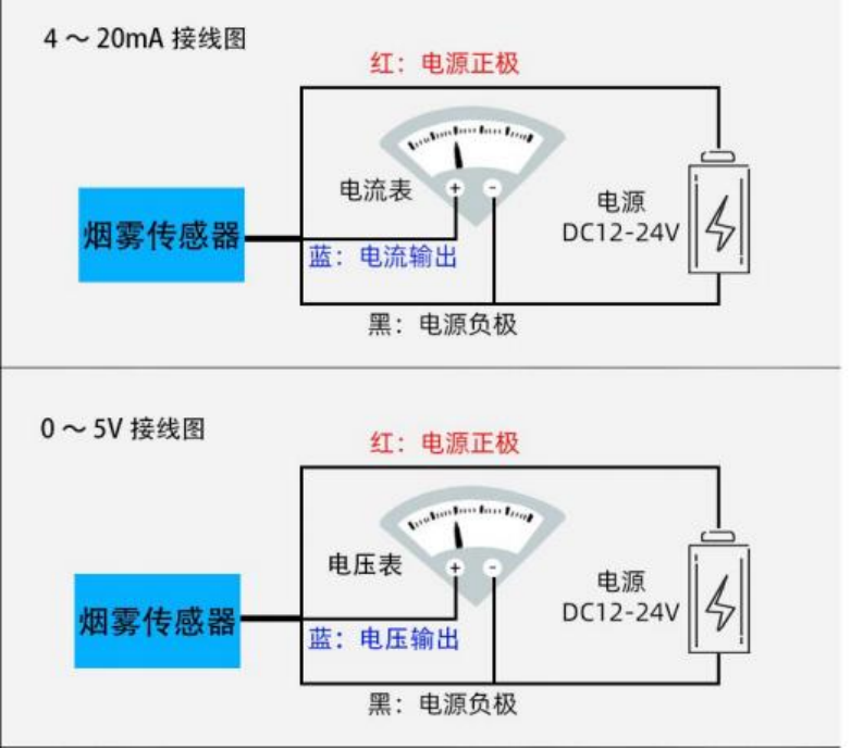
Current type 4~20mA Output, Voltage type 0~5V Output
(1) Wiring diagram
(2) 4~20mA Current type: Smoke and current calculation
Smoke range 0~2000PPM, The analog output is 4~20mA When there is a current signal, Smoke and electricity The formula for calculating the flow relationship: X= (2000-0) *(A-4)÷ (20-4) +0,
Among them 5000 For the upper limit of smoke range, 0 For the lower limit of the measuring range, 20 The upper limit of the current output range, 4 For Lower range limit, A For the current output value, X To calculate the smoke value.
List of commonly used numerical values:
| electric current A(mA) | Smoke value (PPM) | Calculation process |
| 4 | 0.0 | (2000-0) *(4-4)÷ (20-4) +0 |
| 5 | 125 | (2000-0) *(5-4)÷ (20-4) +0 |
| 6 | 250 | (2000-0) *(6-4)÷ (20-4) +0 |
| 7 | 375 | (2000-0) *(7-4)÷ (20-4) +0 |
| 8 | 500 | (2000-0) *(8-4)÷ (20-4) +0 |
| 9 | 625 | (2000-0) *(9-4)÷ (20-4) +0 |
| 10 | 750 | (2000-0) *(10-4)÷ (20-4) +0 |
| 11 | 875 | (2000-0) *(11-4)÷ (20-4) +0 |
| 12 | 1000 | (2000-0) *(12-4)÷ (20-4) +0 |
| 13 | 1125 | (2000-0) *(13-4)÷ (20-4) +0 |
| 14 | 1250 | (2000-0) *(14-4)÷ (20-4) +0 |
| 15 | 1375 | (2000-0) *(15-4)÷ (20-4) +0 |
| 16 | 1500 | (2000-0) *(16-4)÷ (20-4) +0 |
| 17 | 1625 | (2000-0) *(17-4)÷ (20-4) +0 |
| 18 | 1750 | (2000-0) | *(18-4)÷ | (20-4) | +0 |
| 19 | 1875 | (2000-0) | *(19-4)÷ | (20-4) | +0 |
| 20 | 2000 | (2000-0) | *(20-4)÷ | (20-4) | +0 |
As shown in the table, When measuring the current output value 8mA Time, The current smoke concentration value is 500PPM.
(3) 0~5V Voltage type: Smoke and voltage calculation
Smoke range 0~2000PPM, The analog output is 0~5V When there is a voltage signal, Smoke and voltage The formula for calculating the relationship: X=2000*V÷5
Among them 2000 For the upper limit of smoke range, 5 The upper limit of the voltage output range, V Output the current voltage value, X To calculate the smoke value
| Voltage V(V) | Smoke value (PPM) | Calculation process |
| 0 | 0.0 | 2000*0÷5 |
| 0.5 | 200 | 2000*0.5÷5 |
| 1 | 400 | 2000*1÷5 |
| 1.5 | 600 | 2000*1.5÷5 |
| 2 | 800 | 2000*2÷5 |
| 2.5 | 1000 | 2000*2.5÷5 |
| 3 | 1200 | 2000*3÷5 |
| 3.5 | 1400 | 2000*3.5÷5 |
| 4 | 1600 | 2000*4÷5 |
| 4.5 | 1800 | 2000*4.5÷5 |
| 5 | 2000 | 2000*5÷5 |
As shown in the table, When measuring the voltage output value 1.5V Time, The current smoke concentration value is 600PPM.


Leave a Reply