
Airport Site Selection and Aircraft Selection
Users should have prior knowledge of the national policies on unmanned aerial vehicle management and the delineation of local air traffic control areas, and understand the electromagnetic environment, meteorological and geographical conditions, tall trees, large facilities, and building distribution in the flight mission area. When selecting an unmanned aerial vehicle airport, attention should be paid to avoiding restricted flight zones, no fly zones, military control zones, and areas and airspace where strong winds and electromagnetic fields may interfere.
To ensure the safety of personnel, property, and facilities from the threat of unmanned aerial vehicles, avoid the obstruction and shielding of satellite positioning, remote control, and image transmission signals, and prevent buildings and obstacles from affecting the takeoff, landing, and flight safety of aircraft, airports should be installed in outdoor open spaces as far away as possible from crowds, sensitive equipment, cultural relics, valuable facilities, and buildings and obstacles higher than the installation location. Radio frequency ground stations should also be installed at high places as much as possible.
Users should determine the type of task, task area, application payload, range, and plan the route and elevation curve that need to be completed using the aircraft. They should calculate and measure the power consumption and endurance requirements, and include the normal capacity reduction of the battery after multiple cycles of charging and discharging in the analysis. Users should also obtain technical information such as data manuals for unmanned aerial vehicles, understand the takeoff conditions, return landing modes and positioning methods, positioning accuracy, wind resistance, operating temperature range, and other characteristics and performance indicators of the aircraft. The final selected unmanned aerial vehicle model should ensure that the automatic landing horizontal positioning accuracy is not inferior to ± 0.1 meters within the allowable wind speed and visibility range.
Users and installation construction units should carry the main task unmanned aerial vehicle models and related instruments to conduct on-site inspections of alternative airport addresses, traverse possible routes and task areas, measure the quality of geomagnetic disturbances and mobile wireless networks, satellite positioning signals, measure the strength of remote control and image transmission communication signals in various possible flight attitude and orientation conditions, confirm through data recording that geomagnetic disturbances meet the requirements of the extreme application parameters in this manual, and determine that the aircraft can be reliably controlled, images/data can be stably transmitted, and the satellite positioning device and geomagnetic navigation device of the aircraft can work stably without interference within the predetermined mission airspace range of the airport and surrounding areas.
The ground used for airport use should be a flat and open concrete surface with a flatness deviation of less than 5/1000 and not exceeding 10 millimeters. The surface should be free of vegetation, pipelines, ditches, foreign objects, and other equipment and facilities to prevent aircraft from tipping over or colliding with objects during emergency landing. Lightning protection facilities should be installed within a 10 meter radius of the site. The hangar should be located in the center of the largest rectangular area within the site, with the top cover extending parallel to the long side of the rectangle. The length and width of the rectangular area should be no less than 8 meters and 6 meters respectively, and the permanent load capacity of the ground or roof in the area should reach or exceed 10 kilonewtons per square meter. The concrete strength of the hangar support position should not be lower than C30. At least 30 days before installation at the airport, concrete ground should be laid on the newly built site on exposed soil, and a concrete load-bearing platform with the same size as the bottom of the hangar, a protrusion height of not less than 20 centimeters, and a strength of not less than C30 should be poured at the center of the site. The site and load-bearing platform shall not contain ferromagnetic materials such as steel bars and shall ensure that the horizontal slope of their upper surface is within ± 1 °. The scheduled installation location of the meteorological station should be 3 to 5 meters away from the hangar body. Sites with unstable airflow and significant changes in wind speed can consider installing multiple wind speed sensors.
The installation location of hangars and RF meteorological ground stations should have or install outdoor electrical facilities that meet the following requirements.
| Electrical Facilities | Facility Requirements |
| Power Supply | A 220V 50Hz 25A (root mean square effective value) single-phase AC distribution with an enclosure that meets IP54 protection level, good grounding, and leakage protection standards, including at least two national standard three socket outlets (one 25A for hangar use and one 10A for operation and maintenance backup) or providing wiring terminals for direct cable connection. |
| Broadband Network | A wired broadband network that meets IP54 protection level and has a minimum effective upstream and downstream bandwidth of 50Mbps for connection to the external network at any time, including at least one RJ45 socket or providing direct connection to Category 5e Ethernet cables. |
Site selection personnel should confirm that the broadband network can connect to the airport management system. When testing the uplink and downlink bandwidth, relevant tools should be used to measure the actual data upload and download speeds of the installation point network interface connected to the airport management server and video server at multiple different time periods, and obtain statistics on their average and minimum values. The local or internal network connection speed of the network access point cannot be used as an evaluation basis. The following construction layout diagram is for reference only, and the actual layout should be constructed according to the specific site conditions.
The following construction layout diagram is for reference only. The actual layout should be constructed according to the specific site conditions.
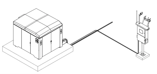
Hangar and RF Box Orientation Diagram 1
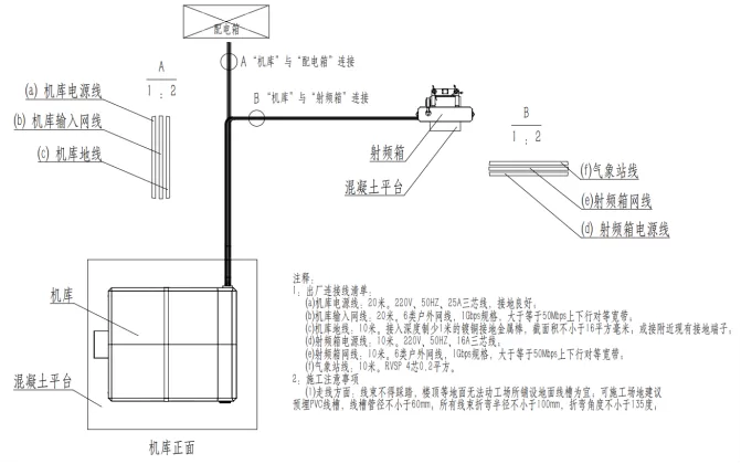
Hangar and RF Box Orientation Diagram 2
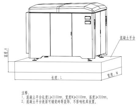
Hangar Placement Platform Diagram 1
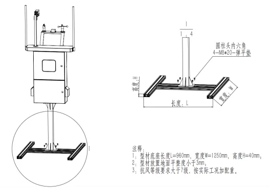
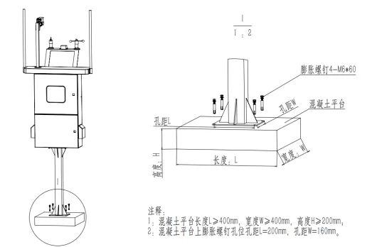
RF Box Installation Method 1
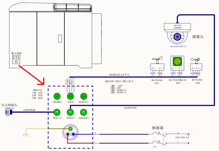
Hangar External Wiring Diagram
Equipment Lightning Protection Measures Plan
I. Lightning Protection Design Principles
Integration: Lightning protection design should comprehensively consider multiple aspects such as direct lightning protection, lightning electromagnetic pulse (LEMP) protection, equipotential connection, and shared grounding system. Scientificity: Based on the lightning activity patterns, topography, and climate conditions of the hangar location, scientifically plan the layout and selection of lightning protection facilities.
Scientificity: Based on the lightning activity patterns, topography, and climate conditions of the hangar location, scientifically plan the layout and selection of lightning protection facilities.
Reliability: Select lightning protection equipment with mature technology and stable performance to ensure the long-term reliable operation of the lightning protection system.
2, Direct lightning protection
1. Lightning rod/Lightning protection strip:
Install lightning rods or strips at the top or around the hangar to directly direct lightning into the ground, avoiding direct lightning strikes from damaging the hangar and its internal drones.
The design of lightning rods/lightning strips should comply with relevant standards to ensure that their protection range covers the entire hangar.
2. Down conductors and grounding devices:
Install sufficient and appropriately spaced down conductors to reliably connect lightning rods/strips to the grounding devices. The down conductor should be made of corrosion-resistant and conductive materials, such as copper or hot-dip galvanized steel. The grounding device should be buried in areas with low soil resistivity, and resistance reduction measures should be taken (such as using resistance reducing agents, expanding the grounding grid area, etc.) to ensure that the grounding resistance meets the specification requirements (generally less than 10 Ω), so that lightning current can quickly leak into the ground.
The grounding device should be buried in areas with low soil resistivity, and resistance reduction measures should be taken (such as using resistance reducing agents, expanding the grounding grid area, etc.) to ensure that the grounding resistance meets the specification requirements (generally less than 10 Ω), so that lightning current can quickly leak into the ground.
III. Lightning Electromagnetic Pulse (LEMP) Protection
1. Shielding Measures:
Perform electromagnetic shielding treatment on key equipment inside the hangar, such as drone charging systems, control systems, etc., to reduce the interference and damage of lightning electromagnetic pulses. The shielding layer can be made of conductive materials such as metal mesh and metal plate, and ensure good grounding.
2. Equipotential bonding:
Implement equipotential bonding measures inside the hangar, reliably connecting all metal components (such as metal doors and windows, pipelines, etc.) and electrical equipment casings to equipotential bonding strips or grounding devices to eliminate the hazards caused by potential differences. Through equipotential connection, it can ensure that the potential of each point inside the hangar is equal or similar, thereby avoiding the phenomenon of potential difference discharge caused by lightning electromagnetic pulses.
By using equipotential connection, it is possible to ensure that the potentials at various points inside the hangar are equal or similar, thereby avoiding the phenomenon of potential difference discharge caused by lightning electromagnetic pulses.
3. Overvoltage protection:
Install overvoltage protection devices (such as surge protectors) on the power lines, signal lines, and other incoming and outgoing lines of the drone hangar to prevent equipment damage caused by overvoltage caused by lightning electromagnetic pulses. The overvoltage protection device should have the characteristics of fast response, high reliability, and low residual voltage to ensure timely and effective protection of equipment safety in the event of lightning.
The overvoltage protection device should have the characteristics of fast response, high reliability, and low residual voltage to ensure timely and effective protection of equipment safety in the event of lightning.
IV. Regular Inspection and Maintenance
Lightning Protection Facility Inspection: Regularly inspect the lightning protection facilities of the hangar, including the integrity of lightning rods/lightning strips, the connection of down conductors, the grounding resistance of grounding devices, etc., to ensure their normal performance.
Maintenance: Perform necessary maintenance work on lightning protection facilities, such as cleaning debris on lightning rods/lightning strips, inspecting and tightening connecting bolts, etc., to ensure the stable operation of the lightning protection system.


Leave a Reply