
VisualHMI is a self-developed serial port screen development software by Dacai, featuring an embedded "virtual serial port screen" (which can simulate the operation of a physical screen on a computer). This article will thoroughly explain the various areas of the interface, engineering settings, and address ranges - address ranges are the foundation for all subsequent development, so it is essential to understand them.
1. Software Installation
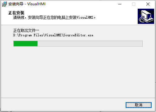
Follow the prompts to select the installation directory and click "Next" to complete the installation. The installation package is usually provided with the development materials or can be downloaded from the official website.
2. Opening the Software Interface
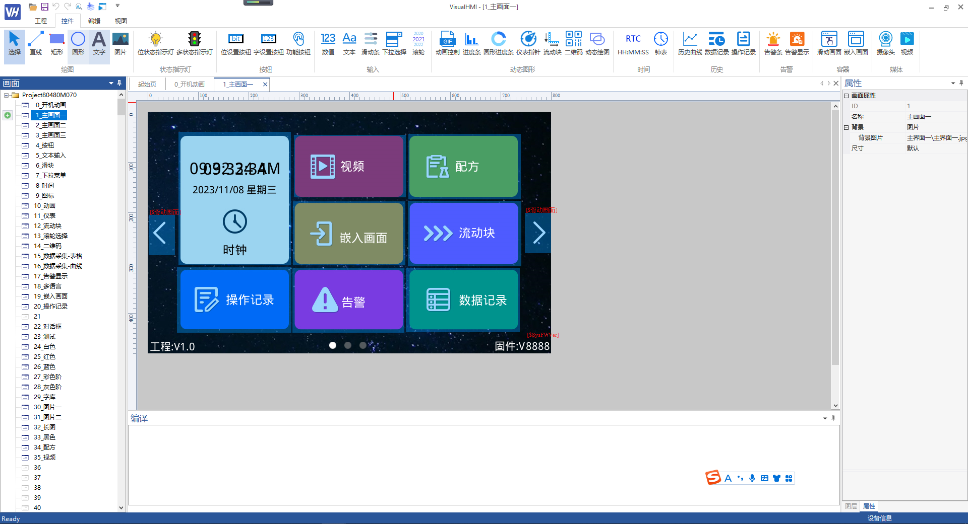
After installation, open an existing factory project, and the interface will appear as follows. It is divided into: top menu bar, left engineering/resource area, middle design area, right attribute/screen area, and bottom debugging area.
3. Engineering Area
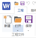
The "Engineering" menu is responsible for project management: new, open, save, save as, etc. When creating a new project, you need to select the resolution and size (corresponding to the physical screen model).

4. Engineering Settings (Key Point)
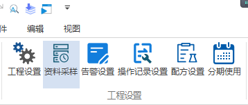
Select "Engineering" → "Engineering Properties" to open the system settings panel, with the core items as follows:
| Setting Item | Description |
|---|---|
| HMI Model | Select your screen model (e.g. HMI80480M070) |
| Flash size | Default 128Mbit, generally no need to change |
| Startup screen | The first screen automatically loaded upon power-on |
| Screen rotation | 0°/90°/180°/270°; for a 800×480 screen, 0° and 180° display 800×480, while 90° and 270° display 480×800 |
| Number of multi-language options | Supports up to 30 languages |
| Automatic standby | Automatically powers down after a set period of no touch activity |
| Baud rate | 9600~921600bps, data bits 7~8, parity odd/even/none, stop bits 1/2 |
| protocol | DCBUS, XGUS, Modbus (master/slave), FX2N, FX3U, Delta, Xinye, Siemens PPI, etc. |
| secure login configuration | permission management, see the "secure login" tutorial |
5. Address range (top priority)
There are two address systems in VisualHMI:HMI local variablesAnd PLC device addresses. Many novices confuse the two systems, leading to controls not refreshing. First, distinguish between them:
HMI local machine (LW / RW variables)
| type | address range (hexadecimal) | description |
|---|---|---|
| system variables | LW0100 ~ LW0FFF | system definitions, such as SysFWVer=LW0155; others reserved for future use |
| user variables | LW1000 ~ LWFFFF | freely usable by users, batch import and export, and address tagging allowed |
| power-down storage variables | RW0000 ~ RW7FFF | Power loss does not cause loss of stored parameters/recipes |
PLC device (taking Modbus as an example)
| Type | Address range (hexadecimal) | Corresponding Modbus zone |
|---|---|---|
| Coil | 0x0000 ~ 0xFFFF | 0x coil (readable and writable bit) |
| Discrete | 1x0000 ~ 1xFFFF | 1x discrete input (readable bit only) |
| Input | 3x0000 ~ 3xFFFF | 3x Input Registers (Read-Only Words) |
| Hold | 4x0000 ~ 4xFFFF | 4x Hold Registers (Read-Write Words) |
The writing method for "Read Address" in the control is like4x0000:4xrepresents the Modbus Hold Register Area, and0000is a hexadecimal address. Select the PLC device location, data type, and address, and the control is bound.
6. Compile/Download Area
- Compile: Check for project errors, and display error messages in the editing area if any
- Compile and run: Pop up a virtual screen, restore the effect of the physical screen 1:1, and can be used in conjunction with virtual serial ports and software for joint debugging
- Mass production guide: Generate download resource packages, support upgrading via SD card / USB flash drive / serial port
7. Resource area (image library / font library / keyboard / sound / tag)
- Image library: All image resources except for the screen background are placed here
- Font library: Vector fonts of any size without jagged edges; check whether the multi-language dependent font library contains the corresponding characters
- Keyboard: Customize the keyboard, up to 10
- Sound: Supports wav/mp3, can be used as keypad tones, startup music, and prompt tones
- Text Label: Centralizes management of multilingual entries, with controls referencing labels, making changes to one entry effective for all
- Address Label: Gives LW/RW/PLC addresses meaningful names (such as "Temperature Setting"), with batch import and export
8. Other Functional Areas
- Data Sampling: Forms a record of data from different registers at the same time for data recording controls/curve display
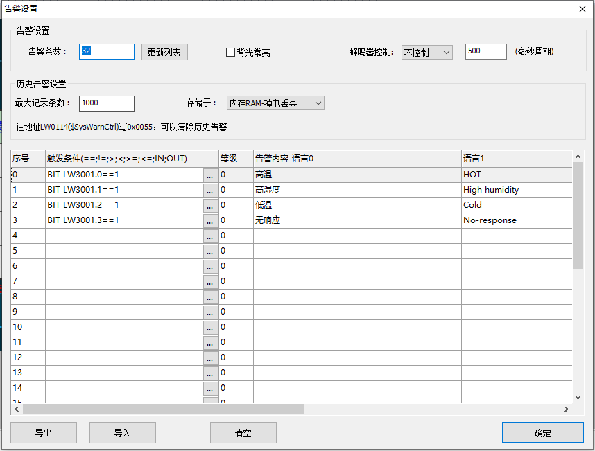
- Alarm Settings: Trigger abnormal prompts when register values change, supports alarms/historical alarms/alarm bars
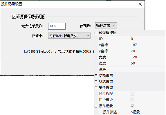
- Operation Records: Records user actions on controls in a table
- Recipe Settings: Different parameter sets for different products/processes, with one-click switching
- Installment Settings: In the context of equipment installment payment, a password prompt appears upon expiration, requiring the entry of the current password to continue usage
- Debugging Area: Select serial port for online debugging and downloading with physical or virtual screen
- Tool Area: LUA script programming, font library cropping entry
- Control Area: Over 30 types of configurable controls (bit status lights, numeric values, text, sliders, gauges, QR codes, videos, etc.)
- Layout Area: Control alignment, spacing, cascading, locking, multi-language preview
- View Area: Zoom Screen, Display Control Address/Comment/ID/Touch
- Screen Area: On the right side, up to 999 screens; the new project by default includes a full keyboard screen 101 (800×480) and a keypad screen 100 (320×240)
Compiled from Guangzhou Dacai Technology VisualHMI Development Documentation (hmi-doc.gz-dc.com) Quick Start "Software Interface", copyright belongs to Dacai Technology.


Leave a Reply