
1
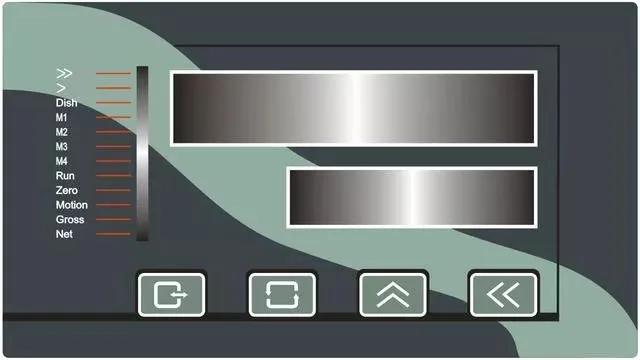
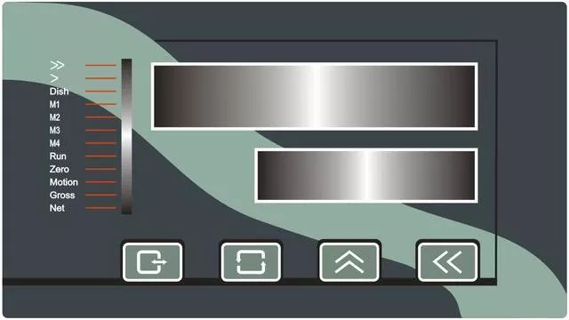
A weighing instrument supporting Modbus protocol
A weighing instrument supporting Modbus protocol
2
Set the communication parameters of the instrument
It can be adjusted according to your own requirements, as long as it is consistent with the PLC side
Baud rate: 9600
Data format: 8n1: 8-bit data/no parity bit
Communication method: Modbus protocol
Checksum: OFF
Instrument communication address: 1
3
Determine the variable address to be read
Here we only need to read the current real-time weight of the instrument

The address of the instrument's real-time weight is 0, corresponding to 40001 in Modbus communication
4
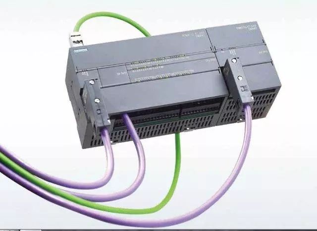
200 smart PLC one unit
5
Connection port
Connect the RS485 interfaces A and B on the instrument side to the DB9 interface on the PLC side (pin 3 of the DB9 interface corresponds to A, and pin 8 corresponds to B).
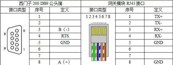
If A and B cannot communicate, they can be swapped.
Preparations are complete. Next, we will start our PLC programming. Since the 200smart software comes with a built-in Modbus protocol library, there is no need to add it separately. Below, we will introduce how to program.
6
Initialize the master station instruction
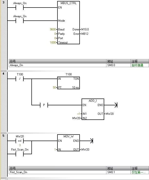
The value entered for "Mode" is used to select the communication protocol. When the input value is 1, the CPU port is assigned to the Modbus protocol and enabled.
The parameter "Parity" should be set to match the parity of the Modbus slave device. 0 (no parity)
The parameter "Port" sets the physical communication port (0 = RS-485 integrated in the CPU).
The parameter "Timeout" is set to the number of milliseconds to wait for a response from the slave. The typical value is 1000 ms (1 s).
When the MBUS_CTRL instruction is completed, the instruction returns "TRUE" to the "Done" output.
The "Error" output contains the result of the instruction execution.
The above parameter settings correspond to the weighing instrument end
7
Polling access of two instruments
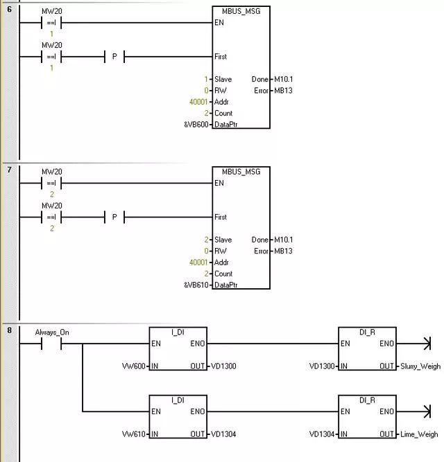
The "Slave" parameter is the address of the Modbus slave device. The allowed range is 0 to 247. Address 0 is a broadcast address. Only use address 0 for write requests. The system will not respond to broadcast requests to address 0. Not all slave devices support broadcast addresses. The S7-200 SMART Modbus slave library does not support broadcast addresses.
Use the RW parameter to indicate whether to read or write the message. 0 (read)
The parameter address (Addr) is the starting Modbus address. The register address is 0, corresponding to address 40001 in Modbus communication
The "Count" parameter is used to allocate the number of data elements to be read or written in the request. The number of register words held in the reading instrument.
The DataPtr parameter is an indirect address pointer that points to the V memory in the CPU associated with the data requested for read. Set DataPtr to the first CPU memory location used to store data read from the Modbus slave.
Instrument data for address 1 is stored in VW600, and instrument data for address 2 is stored in VW610.
Programming completed, let's look at the monitoring results.
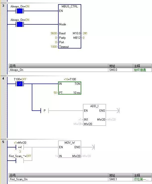
The master initialization command runs normally, with no errors reported
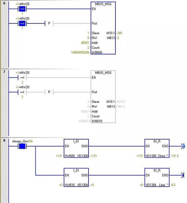
Instrument data for address 1 is 131, and instrument data for address 2 is 0


Leave a Reply