
(I) Overview
Modbus has two serial transmission modes: ASCII and RTU. Modbus is a master-slave communication mode with a single master station. Only one master station can exist on the Modbus network, and the master station does not have an address on the Modbus network. Each slave station must have a unique address, with the address range of 0 - 247, where 0 is the broadcast address, and the actual address range of the slave station is 1-247. Modbus RTU communication performs data transmission in a master-slave manner. During transmission, the Modbus RTU master station is the initiator, that is, the master station sends data request messages to the slave station, and the Modbus RTU slave station returns response messages. The following modules of S7-1200 support Modbus RTU communication:
| Communication module/communication board | Order number |
| CM1241 RS232 | 6ES7241-1AH32-0XB0 |
| CM1241 RS422/485 | 6ES7241-1CH32-0XB0 |
| CB 1241 RS485 | 6ES7241-1CH30-1XB0 |
Note:
(1) When using the communication module CM 1241 RS232 as the Modbus RTU master station, it can only communicate with one slave station.
(2) When using the communication module CM 1241 RS485 as a Modbus RTU master, it is allowed to establish communication with up to 32 slaves.
(3) When using the communication board CB 1241 RS485, the CPU firmware must be V2.0 or higher, and the software used must be STEP 7 Basic V11 or STEP 7 Professional V11 or a later version.
(II) Modbus RTU Instruction Versions and Restrictions
With the continuous updates of the Siemens Simatic Automation Suite (Simatic) software and S7-1200 CPU firmware, different versions of the S7-1200 Modbus RTU instructions have emerged. Users need to correctly select and use the appropriate S7-1200 Modbus RTU instructions according to the software and hardware they are using to implement Modbus RTU communication. The software and hardware requirements and instruction version descriptions are as follows.
(1) Modbus RTU Instructions in Simatic
Simatic provides two versions of Modbus RTU instructions. As shown in Figure 1 below:
- The early version of the Modbus RTU instructions (MODBUS (V2.2) in Figure 1) can only be used for Modbus RTU communication through the CM1241 communication module or CB1241 communication board.
- The new version of the Modbus RTU instructions (MODBUS(RTU) V3.0 in Figure 1) expands the functionality of Modbus RTU. In addition to supporting the CM1241 communication module and CB1241 communication board, this instruction also supports Modbus RTU communication through the PTP communication module on the PROFINET or PROFIBUS distributed I/O rack.
(2) Restrictions on the use of new version Modbus RTU commands
When the new version of Modbus RTU instructions are used for Modbus RTU communication through the CM1241 communication module or CB1241 communication board, the following conditions must be met:
The firmware version of the S7-1200 CPU must not be lower than V4.1
b. CM1241 communication module version 2.1 or above, or CB1241
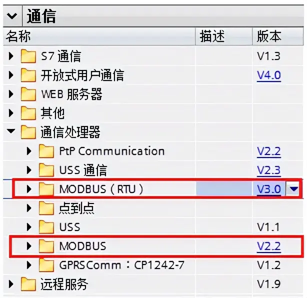
Figure 1. Two Versions of Modbus RTU Instructions
(III) Common Issues
(1) Does the S7-1200 support Modbus ASCII communication mode?
Siemens does not provide ready-made instructions supporting the above communication mode, and users need to program in free port mode.
(2) What is the difference between Modbus RTU Instruction Versions V1 and V2?
Modbus RTU Instruction Version V2 adds the parameters "REQ" and "DONE" to the "MB_COMM_LOAD" instruction. Furthermore, the "MB_ADDR" parameter of the "MB_MASTER(Image)" and "MB_SLAVE" instructions now allows a UInt value for extended addressing.
(3) Can different versions of Modbus RTU instructions, V1 and V2, be used simultaneously in the same CPU program?
It is not possible to use both V1 (V1.x) and V2 (V2.y) instruction versions simultaneously in the same CPU program. The Modbus instructions in the user program must have the same major version number; instructions within the same major version group can have different minor version numbers.
(4) Can the S7-1200 communication module CM1241 be used as a Modbus RTU master or as a Modbus RTU slave?
The S7-1200 communication module CM1241 can be configured and programmed to call the "MB_COMM_LOAD" instruction, setting it to Modbus RTU communication mode. By programming and calling the "MB_MASTER" instruction, the S7-1200 communication module CM1241 can be used as a Modbus RTU master, or by calling the "MB_SLAVE" instruction, it can be used as a Modbus RTU slave.
Note:Regardless of whether the S7-1200 communication module CM1241 is used as a Modbus RTU master or slave, it is necessary to call the "MB_COMM_LOAD" instruction for programming.
(5) Does the S7-1200 CM1241/CB1241 Modbus RTU communication support two stop bits?
Yes, it does.
Note:The stop bits can be set in the properties of the S7-1200 CM1241/CB1241, but when this module is used for Modbus communication, the set stop bits are invalid. It is necessary to modify the STOP_BITS stop bit value to 2 in the background DB of the Modbus_Commload instruction. As shown in Figure 2-3 below:
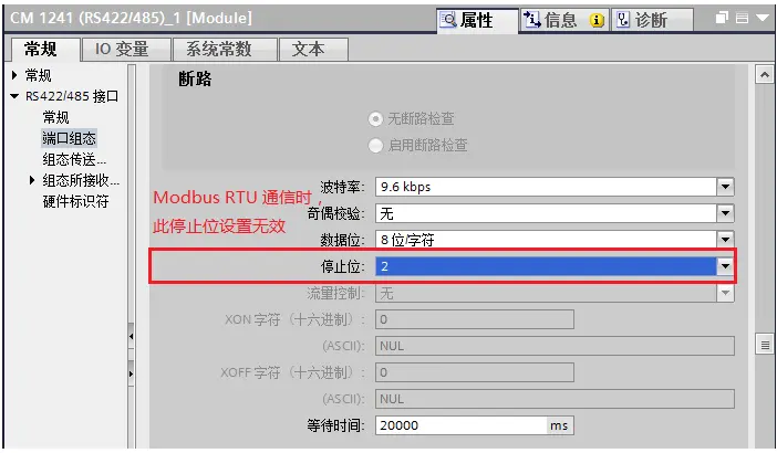
Figure 2. CM1241 Stop Bit Configuration Parameters
Modify the STOP_BITS stop bit value to 2 (default value=1) in the background DB of the Modbus_Commload instruction
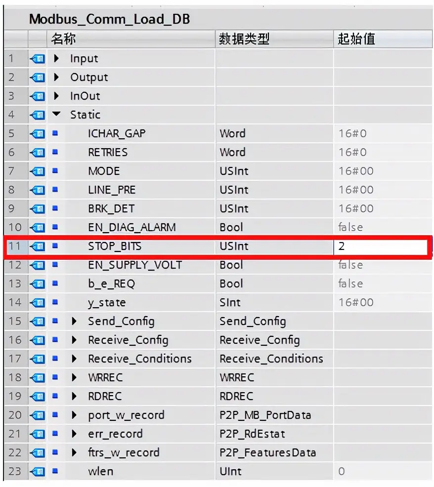
Figure 3. Modify the Modbus RTU Communication Stop Bits
Part II: V3 Instruction Functions
(I) Overview of Modbus RTU Instructions
The software in the B&R V13 SP1 version provides two versions of Modbus RTU instructions:
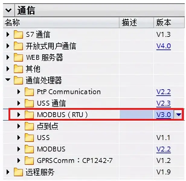
Figure 1. Two Versions of Modbus RTU Instructions
(1) The early version of Modbus RTU instructions (MODBUS (V2.2) in Figure 1) can only perform Modbus RTU communication through the CM1241 communication module or CB1241 communication board.
(2) The new version of Modbus RTU instructions (MODBUS(RTU) V3.0 in Figure 1) extends the functionality of Modbus RTU. In addition to supporting the CM1241 communication module and CB1241 communication board, this version also supports the PTP communication module on the PROFINET or PROFIBUS distributed I/O rack for Modbus RTU communication.
(3) The PTP modules supported by the new version of Modbus RTU instructions are shown in Figure 2 below:
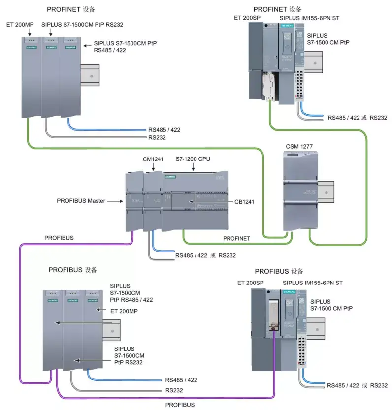
Figure 2. PTP Modules Supported by the New Version of Modbus RTU Instructions
(II) Introduction to the Modbus RTU Instruction Instance Environment
The new version of Modbus RTU instructions includes both Modbus RTU master and slave instructions. This article takes the CPU1217C+CM1241 RS422/485+ET200SP CM PTP module as an example to introduce the programming steps for master-slave communication using the new version of Modbus RTU instructions. In this configuration, the CPU rack CM1241 RS422/485 serves as the Modbus RTU slave, and the CMPTP module in the distributed rack ET200SP serves as the Modbus RTU master.
1. The network structure diagram is as follows:
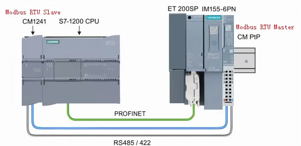
Figure 3. Modbus RTU Network Communication Structure Diagram
2. The hardware and software used in this project are as follows:
(1) Hardware:
① CPU1217C (order number: 6ES7 217-1AG40-0XB0), firmware version V4.1.3
② CM1241 RS422/485 module (order number: 6ES7 241-1CH32-0XB0), firmware version V2.1
③ 24V power supply PS307 (order number: 6ES7307-1KA02-0AA0)
④ ET200 SP IM155-6PN HF (order number: 6ES7155-6AU00-0CN0)
⑤ CM PTP module (order number: 6ES7137-6AA00-0BA0)
(2) Software:
① Siemens Simatic S7-1200 SP1 UP 9
(III) Device configuration of the instance
1. Configure the CM1241 RS422/485 module
(1) Open the device view, add the S7-1200 CPU, and navigate to "Communication Modules" → "Point-to-Point" → "CM1241 (RS422/485)" in the hardware directory. Drag this module to the left side of the CPU, as shown in Figure 4 below:
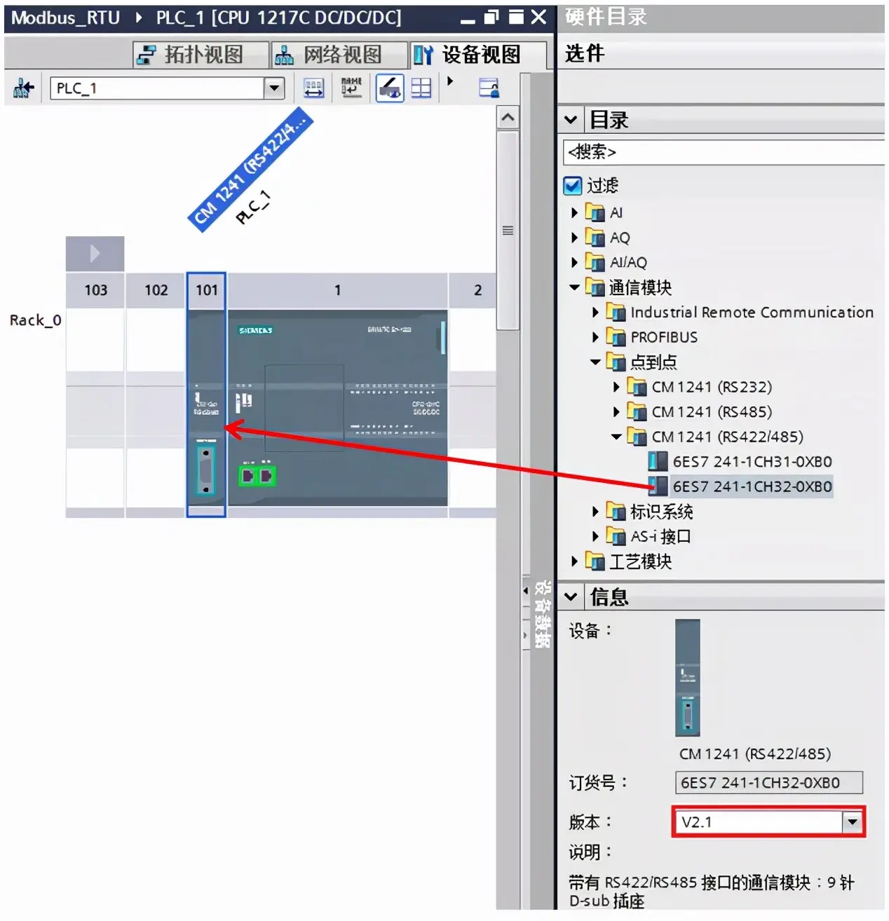
Figure 4. Adding CM 1241 RS422/485 module
Note: Only CM 1241 RS422/485 modules with firmware version >= V2.1support the new version of Modbus RTU instructions.
(2) Next, select the CM1241 (RS422/485) module in the "Device View" with the mouse, and configure the hardware interface parameters of this module in "Properties" → "Port Configuration". In this example, the transmission rate is set to 9.6Kbps, parity is set to "No Parity", data bits are set to "8-bit characters", and stop bits are set to "1". The CM1241 port configuration is shown in Figure 5 below:
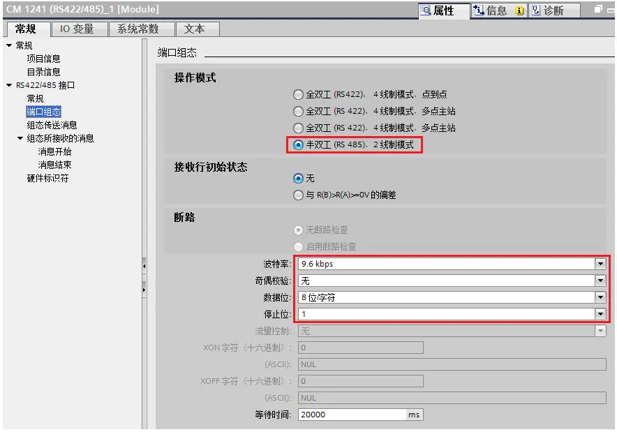
Figure 5. Port Configuration of CM1241 RS422/485 Module
(3) Finally, confirm that the hardware identifier is 269 (this parameter will be used in program programming) in "Hardware Identifier", as shown in Figure 6 below:
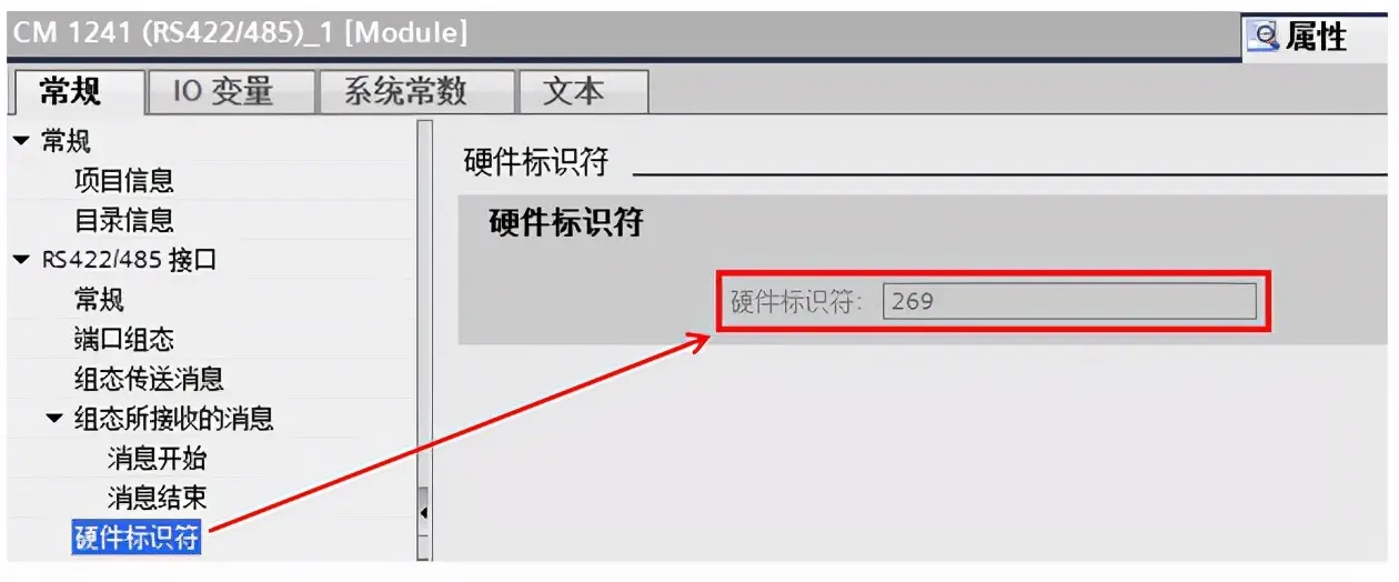
Figure 6 Hardware Identifier
(4) In addition, the S7-1200 also provides system and clock memory functions. To facilitate subsequent instructions, it is recommended to enable this function. Enable the system and clock memory functions in the CPU "Properties" → "General" → "System and Clock Memory", as shown in Figure 7.
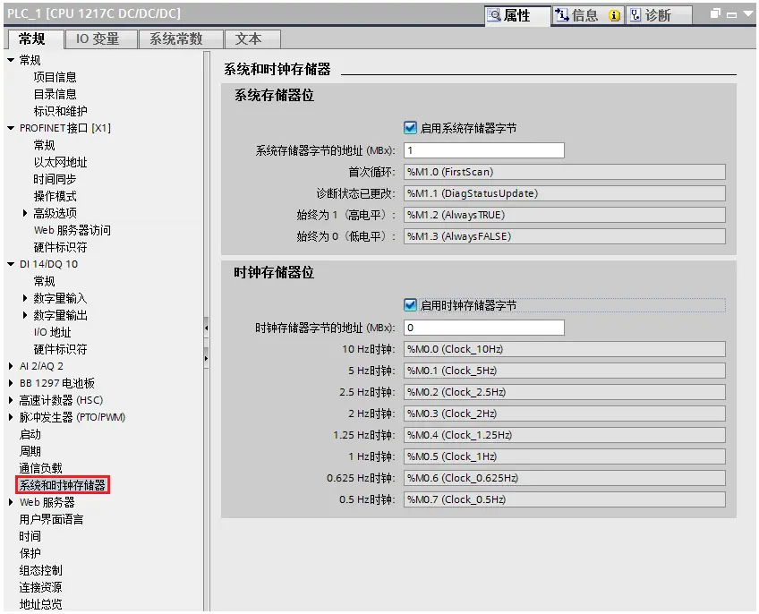
Figure 7. System and Clock Memory Function
2. Configure ET200 SP CM PtP Module
(1) Insert an ET200SP distributed site, open the network view, drag in an ET200SP site, and assign it to the corresponding IO controller (in this example, CPU1217C is the IO controller), as shown in Figure 8:
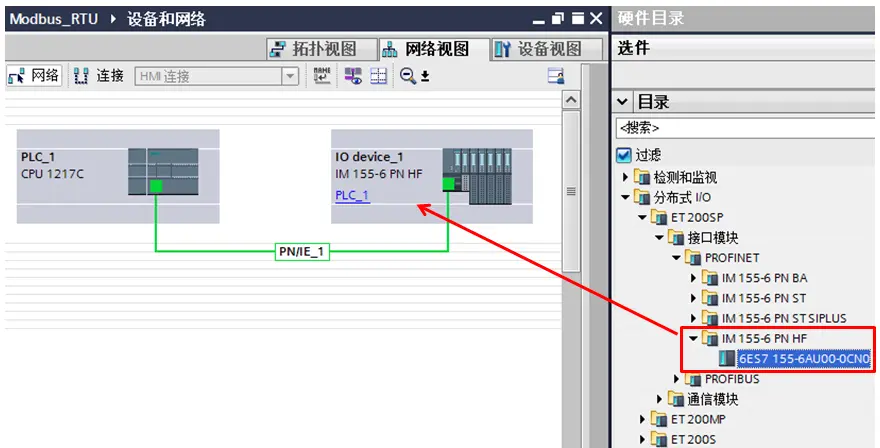
Figure 8. Insert ET200SP Site
(2) Configure the ET200SP site. In the ET200SP "Device View" environment, add signal, communication, and server modules to the ET200SP site. In this example, only the CM PTP module and server module are added.
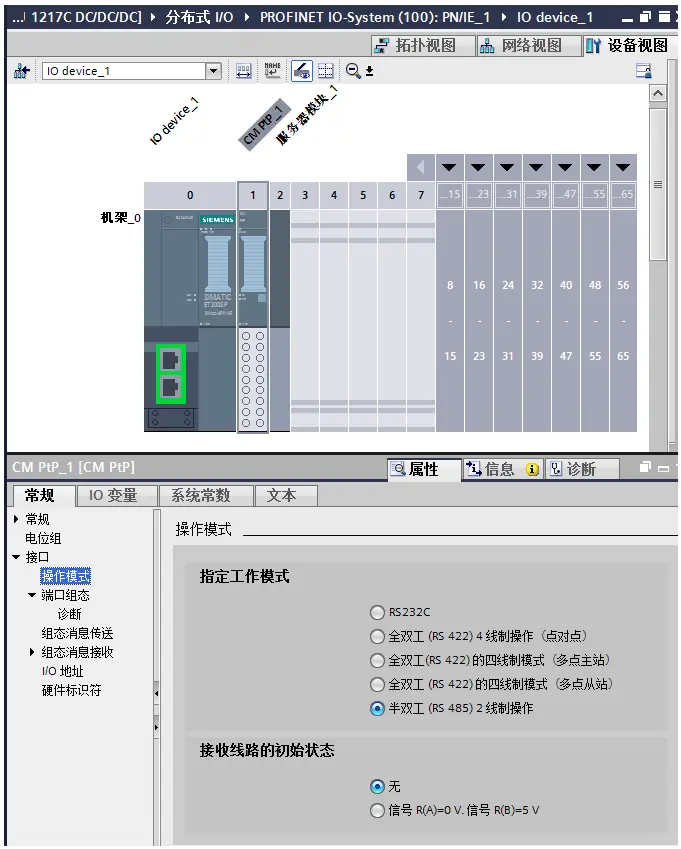
Figure 9. CM PTP Operation Mode
Note: In the ET200SP station, the server module must be configured. The server module is purchased together with the interface module and does not need to be purchased separately.The ET200SP interface module requires an IP address and a Device Name to be assigned. For detailed steps on configuring the ET200 SP distributed IO, please refer to the "Quick Start Guide for ET200 SP". This example will not cover the related settings and steps for Profinet IO communication. Download link for "Quick Start Guide for ET200 SP":
https://support.industry.siemens.com/cs/cn/zh/view/78304711
(3) Next, configure the port configuration parameters of this module in "Properties" → "General" → "Interfaces" → "Port Configuration". In this example, the "Protocol" is set to "Freeport/Modbus"; the "Port Parameters" are set as follows: Transmission Rate = 9.6Kbps, Parity = No Parity, Data Bits = 8 Bits, Stop Bits = 1. The port configuration settings are shown in Figure 10 below:
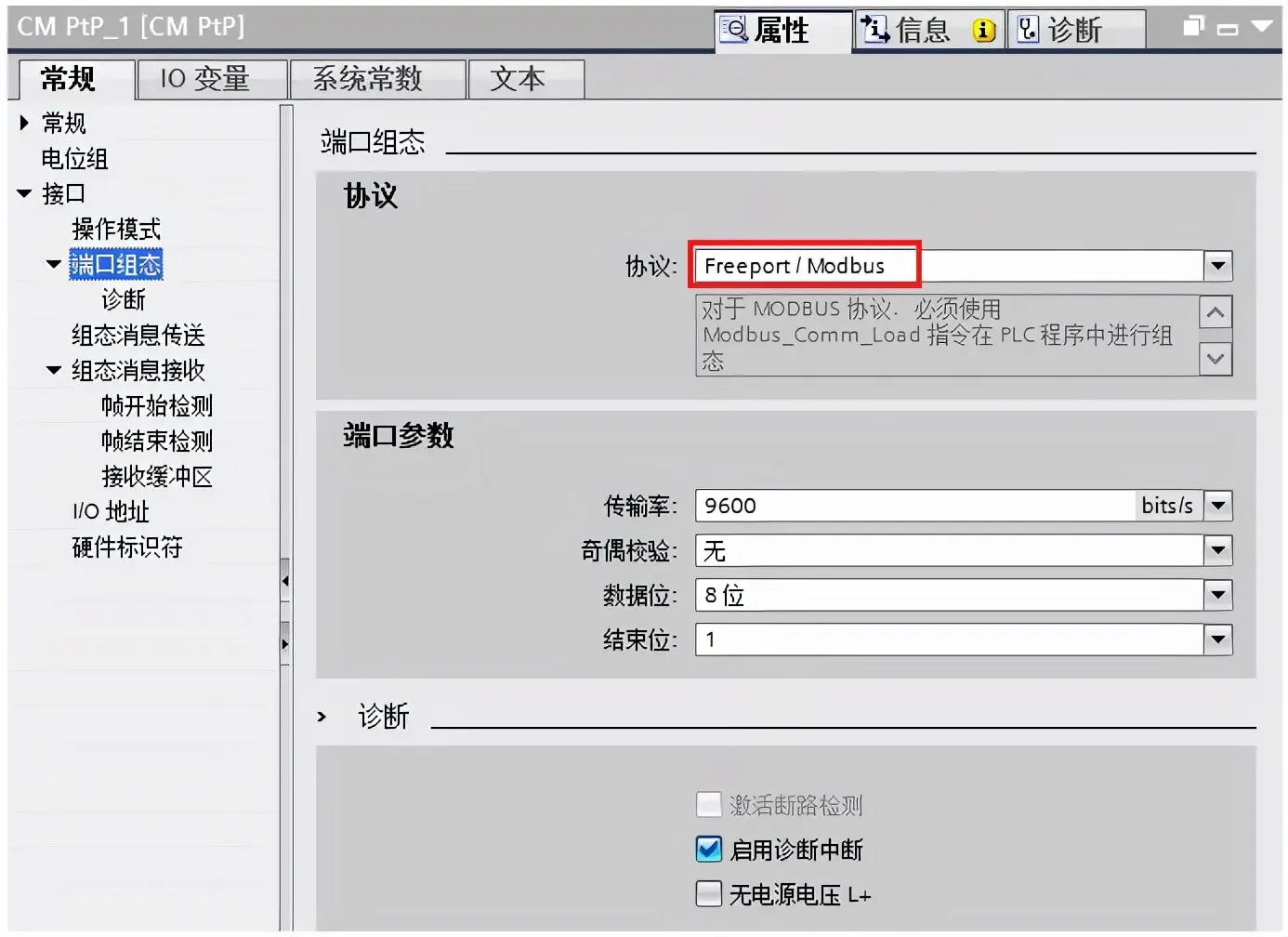
Figure 10. CM PTP Port Configuration
(4) Finally, confirm the hardware identifier of the CM PTP module in the "Hardware Identifier" field, as this parameter will be used in program programming.
(IV) Software Programming for Instance
1. Modbus RTU Master Programming
Modbus RTU master programming requires the use of the Modbus_Comm_Load and Modbus_Master instructions. The Modbus_Comm_Load instruction configures the communication module through the Modbus RTU protocol, while the Modbus_Master instruction can communicate as a Modbus master through the port configured by the Modbus_Comm_Load instruction. The MB_DB parameter of the Modbus_Comm_Load instruction must be connected to the (static) MB_DB parameter of the Modbus_Master instruction. In this example, the CM PTP module in the distributed rack ET200SP serves as a Modbus RTU master, and the relevant programming steps are as follows:
(1) Insert an FC function in OB1, and drag the Modbus_Comm_Load and Modbus_Master instructions into the function.
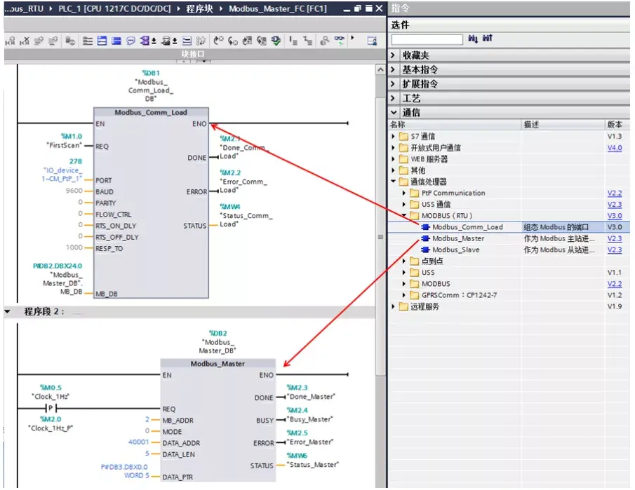
Figure 11. Drag-in Modbus RTU Master Command
The meanings of the parameters for the Modbus_Comm_Load command are shown in Table 1 below:
| pin | Description |
| REQ | Rising edge trigger |
| PORT | Hardware identifier of the communication port |
| BAUD | Baud rate selection: 3600, 6000, 12000, 2400, 4800, 9600, 19200, 38400, 57600, 76800, 115200 |
| PARITY | Parity check selection: 0 - None; 1 - Odd parity; 2 - Even parity |
| FLOW_CTRL | Flow control selection: 0 - (Default) No flow control |
| RTS_ON_DLY | RTS delay selection: 0 - (Default) |
| RTS_OFF_DLY | RTS off delay selection: 0 - (Default) |
| RESP_TO | Response timeout: Default = 1000 ms. The time allowed by MB_MASTER for a slave response, in milliseconds. |
| MB_DB | Reference to the background data block of a Modbus_Master or Modbus_Slave instruction. The MB_DB parameter must be connected to the static variable MB_DB parameter in the Modbus_Master or Modbus_Slave instruction. |
| DONE | If the previous request is completed without error, the DONE bit will become TRUE and remain so for one cycle. |
| ERROR | If the previous request is completed with an error, the ERROR bit will become TRUE and remain so for one cycle. The error code in the STATUS parameter is only valid during the cycle when ERROR = TRUE. |
| STATUS | Port configuration error codes, please refer to the TIA software online help or the S7-1200 system manual. |
Table 1: Meaning of MB_COMM_LOAD instruction parameters
Meaning of each parameter of the Modbus_Master instruction is shown in Table 2 below:
| Pin | Description |
| EN | Enable terminal |
| REQ | TRUE = Request to send data to a Modbus slave, recommended to use rising edge triggering. |
| MB_ADDR | Modbus RTU slave address. Default address range: 0 to 247; Extended address range: 0 to 65535. The value 0 is reserved for broadcasting messages to all Modbus slaves. |
| MODE | Mode selection: Specify the request type (read or write). |
| DATA_ADDR | Starting address in the slave: Specify the starting address of the data to be accessed in the Modbus slave. |
| DATA_LEN | Data length: Specify the number of bits or words to be accessed in this request. |
| DATA_PTR | Data pointer: Point to the tag or data block address where data writing or data reading is to be performed. |
| DONE | DONE bit: After the previous request has been completed without errors, the DONE bit will remain TRUE for one scan cycle. |
| BUSY | FALSE – Modbus_Master has no active command: TRUE – Modbus_Master command execution in progress |
| ERROR | Reference to the background data block of the Modbus_Master or Modbus_Slave instruction. The MB_DB parameter must be connected to the static variable MB_DB parameter in the Modbus_Master or Modbus_Slave instruction. |
| STATUS | If the previous request is completed without error, the DONE bit will become TRUE and remain TRUE for one cycle. |
| ERROR | If the previous request is completed with an error, the ERROR bit will become TRUE and remain TRUE for one cycle. The error code in the STATUS parameter is only valid during the cycle when ERROR = TRUE. |
| STATUS | Error code |
Table 2: Meaning of Modbus_Master instruction parameters
Note:
① The Modbus_Comm_Load instruction is not recommended to be called in the startup block OB100, and it is recommended to call it in OB1. When the Modbus_Comm_Load instruction is called in OB1, its input bit "REQ" needs to be triggered by a rising edge, and in this example, the input bit uses the "FirstScan" system memory bit.
② The static variable "MODE" in the background data block of the Modbus_Comm_Load instruction is used to describe the working mode of the PTP module, and the valid working modes include:
- 0 = Full duplex (RS232)
- 1 = Full duplex (RS422) four-wire mode (point-to-point)
- 2 = Full-duplex (RS 422) 4-wire mode (Multi-drop Master, CM PtP (ET 200SP))
- 3 = Full-duplex (RS 422) 4-wire mode (Multi-drop Slave, CM PtP (ET 200SP))
- 4 = Half-duplex (RS485) 2-wire mode
The default value of the static variable "MODE" is 0 (RS232 full-duplex mode). This value needs to be modified according to the actual configuration of the CM PTP module. In this example, the CM PTP module operates in RS485 half-duplex mode, so the value needs to be changed to 4, as shown in Figure 12:
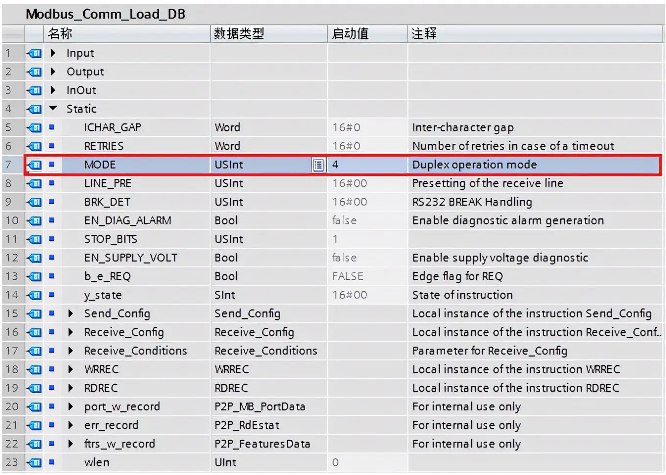
Figure 12. Modify the static variable "MODE" of the Modbus_Comm_Load background data block to
③ The "DATA_PTR" parameter of the Modbus_Master instruction is used to point to the address of the data area where data is to be written or read. This data area supports optimized access data blocks or non-optimized (standard) data blocks. It is recommended to use non-optimized access data blocks.
In this example, the data area used is a non-optimized access data block. To modify the data block to a non-optimized access data block, simply cancel "Optimized Block Access" in the data block's properties (right-click on the data block, select "Properties", and cancel "Optimized Block Access"), as shown in Figure 13:
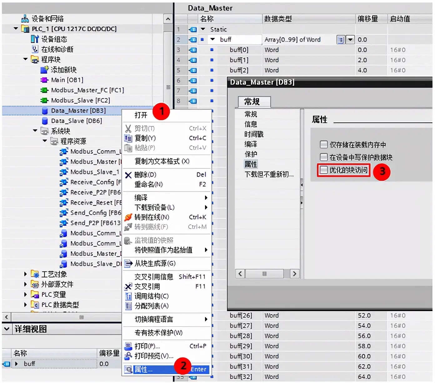
Figure 13. Set the data block to non-optimized access
When the "DATA_PTR" of the Modbus_Master instruction points to a non-optimized access data block, this input parameter needs to be filled in using a pointer format, such as P#DB3.DBX0.0 WORD 5.
④ When there are multiple Modbus RTU slaves or a single Modbus RTU slave in the Modbus RTU network that requires both read and write operations simultaneously, multiple Modbus_Master instructions need to be called, and these Modbus_Master instructions need to be called using a polling method.
The following Figure 14 describes the polling method for calling two Modbus_Master instructions.
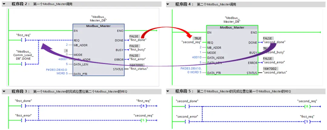
Figure 14. Modbus_Master polling call method
(2) Insert "Pull or plug of modules" to interrupt OB83
In this example, the Modbus RTU master module is installed on a distributed IO site, so the program needs to consider faults such as distributed IO site failures and CM PTP module insertion and removal. When modules are plugged in or out of the distributed IO site, the operating system will call OB83 once. The faulty module and type can be determined through the input variable "16#Event_Class" in the OB83 interface area: event type 16#39 indicates that the module has been pulled out, and event type 16#38 indicates that the module has been plugged in. When the CM PTP module is re-plugged in, the Modbus_Comm_Load instruction needs to be called in the interrupt OB83 to reconfigure the communication module, as shown in Figure 15.
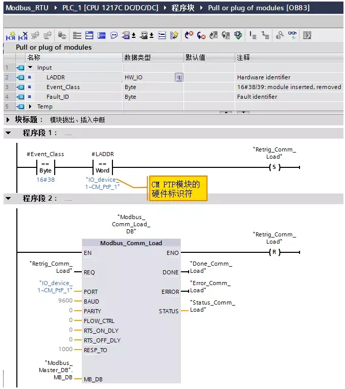
Figure 15. Re-calling Modbus_Comm_Load instruction in OB83
Note:
① The background data block for calling the Modbus_Comm_Load instruction in OB83 needs to be the same as the background data block for calling the Modbus_Comm_Load instruction in OB1.
② The hardware identifier of the CM PTP module can also be queried in "PLC Variables" ---> "System Constants", as shown in Figure 16:
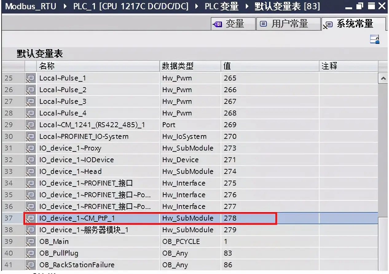
Figure 16. System Constants
(3) Insert "Rack or Station failure" to interrupt OB86
When the distributed IO site fails and recovers, the operating system will call OB86 once. The faulty module and type can be determined through the input variable "16#Event_Class" in the OB86 interface area: event type 16#39 indicates site failure, and event type 16#38 indicates site recovery.
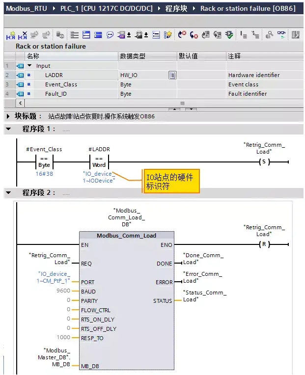
Figure 17. Calling the Modbus_Comm_Load instruction in OB86
Note:
① The background data block for the Modbus_Comm_Load instruction called in OB86 must be the same as the background data block for the Modbus_Comm_Load instruction called in OB1.
② The hardware identifier of the distributed IO site can also be queried in "PLC Variables" ---> "System Constants".
2. Modbus RTU Slave Programming
Modbus RTU slave programming requires the use of the Modbus_Comm_Load and Modbus_Slave instructions. The Modbus_Comm_Load instruction configures the communication module through the Modbus RTU protocol, while the Modbus_Slave instruction enables communication as a Modbus slave through the port configured by the Modbus_Comm_Load instruction. The MB_DB parameter of the Modbus_Comm_Load instruction must be connected to the (static) MB_DB parameter of the Modbus_Slave instruction. In this example, the CPU rack CM1241 RS422/485 serves as a Modbus RTU slave, and the relevant programming steps are as follows:
(1) Insert an FC function in OB1, and drag the Modbus_Comm_Load and Modbus_Slave instructions into the function. As shown in Figure 18:
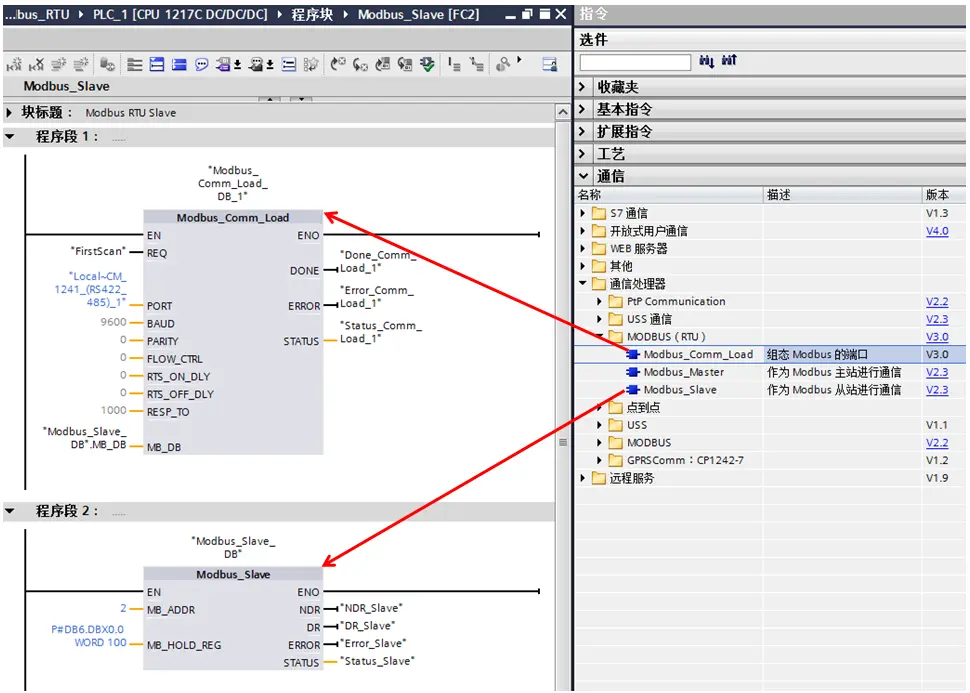
Figure 18. Dragging the Modbus RTU Slave Instruction
The parameters of the Modbus_Slave instruction are described in Table 3 below:
| Pin | Description |
| MB_ADDR | Standard addressing for Modbus slaves: Standard addressing range (1 to 247) Extended addressing range (0 to 65535) |
| MB_HOLD_REG | Data pointer, pointing to the address of the Modbus hold register, which can be either the M memory area or the DB data area. If the Modbus hold register is in the DB data area, the DB data area supports optimized access data blocks or non-optimized access data blocks, and it is recommended to use non-optimized access data blocks. |
| NDR | Available new data: FALSE - No new data TRUE - Indicates that new data has been written by the Modbus master. If the previous request is completed without errors, the NDR bit will become TRUE and remain TRUE for one cycle. |
| DR | Read data: FALSE - No new data TRUE - Indicates that the instruction has stored the data received by the Modbus master in the target area. If the previous request is completed without errors, the DR bit will become TRUE and remain TRUE for one cycle. |
| ERROR | If the previous request is completed with errors, the ERROR bit will become TRUE and remain TRUE for one cycle. If the execution is terminated due to an error, the error code in the STATUS parameter is only valid during the cycle when ERROR = TRUE. |
| STATUS | Error code |
Table 3: Meaning of Modbus_Slave instruction parameters
Note:
① The Modbus_Comm_Load instruction is not recommended to be called in the startup organization block OB100, and it is recommended to call it in OB1. When the Modbus_Comm_Load instruction is called in OB1, its input bit "REQ" needs to be triggered by a rising edge, and in this example, this input bit uses the "FirstScan" system memory bit.
② The static variable "MODE" in the background data block of the Modbus_Comm_Load instruction is used to describe the working mode of the PTP module. Valid working modes include:
- 0 = Full-Duplex (RS232)
- 1 = Full-Duplex (RS422) 4-Wire Mode (Point-to-Point)
- 2 = Full-Duplex (RS 422) 4-Wire Mode (Multi-Drop Master, CM PtP (ET 200SP))
- 3 = Full-Duplex (RS 422) 4-Wire Mode (Multi-Drop Slave, CM PtP (ET 200SP))
- 4 = Half-Duplex (RS485) 2-Wire Mode
The default value of this static variable "MODE" is 0 (RS232 Full-Duplex mode). This value needs to be modified according to the actual configuration of the CM1241 RS422/485 module. In this example, where the CM1241 RS422/485 module is operating in RS485 Half-Duplex mode, the value should be changed to 4. How to modify the "MODE" static variable is shown in Figure 12.
③ The "MB_HOLD_REG" of the Modbus_Slave instruction is used to point to the address of the data area of the Modbus Hold Register. This data area supports optimized access data blocks or non-optimized (standard) data blocks. It is recommended to use non-optimized access data blocks. In this example, the data area used is a non-optimized access data block, so this input parameter needs to be filled in using a pointer, such as P#DB6.DBX0.0 WORD 100. How to cancel "Optimized Block Access" in the data block properties is shown in Figure 13. Download the program to the PLC and connect the CM1241 RS422/485 to the CM PTP serial port module using a Profibus DP communication cable to test Modbus RTU communication.
(V) Common Problems
1. Are there any restrictions on the use of the new version of Modbus RTU instructions?
When the new version of Modbus RTU instructions are used for Modbus RTU communication through the CM1241 communication module or CB1241 communication board, the following conditions must be met:
a. The firmware version of the S7-1200 CPU must not be lower than V4.1;
b. The firmware of the CM1241 communication module or CB1241 communication board cannot be lower than V2.1.
The firmware CPU of S7-1200 V4.0 can be updated to version V4.1 through firmware update, and the CM1241 communication module with firmware V2.0 can also be updated to version V2.1 through firmware update. For the method of firmware update, please refer to S7-1200 firmware update.
2. What is the role of the static variable "MODE" in the background data block of the Modbus_Comm_Load instruction? Why is it necessary to modify this variable in general projects?
The new version of the Modbus RTU instruction extends the functionality of Modbus RTU. In addition to supporting the CM1241 communication module and CB1241 communication board, this instruction also supports the PTP communication module on the PROFINET or PROFIBUS distributed I/O rack for Modbus RTU communication. The PTP communication module on the distributed I/O rack supports multiple working modes. Taking the ET200SP CM PtP module (order number: 6ES7137-6AA00-0BA0) as an example, it supports multiple working modes such as RS232, RS485, and RS422. The static variable "MODE" in the background data block of the Modbus_Comm_Load instruction is used to define the working mode of the PtP module. The default value of "MODE" is 0, representing the "full duplex (RS232)" working mode. In actual project configuration, this variable needs to be modified according to the actual working mode.
3. Can the Modbus_Comm_Load instruction be called in the start-up block OB100?
It is not recommended to call the Modbus_Comm_Load instruction in the start-up block OB100. The new version of the Modbus RTU instruction extends the functionality of Modbus RTU. This instruction supports the PtP communication module on the PROFINET or PROFIBUS distributed I/O rack for Modbus RTU communication. The operating system needs to call instructions such as reading data records and writing data records to achieve Modbus RTU communication with the PtP module on the distributed I/O rack.
4. How to query the error code in case of Modbus RTU communication error?
Taking the Modbus_Master instruction as an example, when a communication error occurs, the "ERROR" output bit of the Modbus_Master instruction will become TRUE but only remain TRUE for one scanning cycle. Therefore, the error cannot be queried when monitored through the TIA software program. The error code in the "STATUS" parameter of the Modbus_Master instruction is only valid during the scanning cycle when "ERROR" = TRUE. To obtain the error code of a Modbus RTU communication error, we can program using the method shown in Figure 19 below.
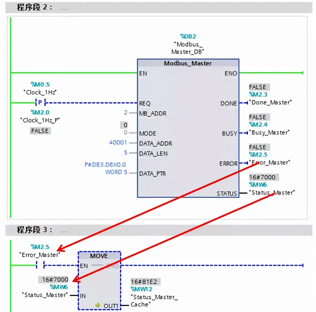
Figure 19. Obtaining STATUS


Leave a Reply