
2 How to create associated variables
Jump symbol serial port screen modbus protocol supports the creation of coils, discrete inputs, holding registers, input registers, content variables, and system variables, as shown below

| Variable type | Related description |
|---|---|
| Coils | Participating in communication: 0x01/0x05/0x0F |
| Discrete Input | Participating in communication: 0x02 |
| Holding Register | Participating in communication: 0x03/0x06/0x10 |
| Input Register | Participating in communication: 0x04 |
| Memory variables | do not participate in communication: used as intermediate variables, to record some information, etc. |
| System variables | do not participate in communication: such as system baud rate, running time, etc. |
The screen configuration in this chapter is set to host mode, introducing the creation and binding of coils, discrete inputs, hold registers, input registers, and system variables.
Scope of application: full series.
For protocol activation and variable-related instructions, refer to the link: "Modbus Basic Parameter Description".
2.1 Coils
The [Coil] interface is used to display and control the state of the "Coil" variable in the MODBUS protocol. The button control is directly bound to the "Coil" type variable. The state of the coil is 0 or 1, corresponding to the button being up (0) or pressed (1). After running, when the "Coil" value at that address changes, the state of the button control changes in real time. Similarly, by clicking the button, the state of the coil variable type corresponding to the address in the slave device can be changed
Variable configuration
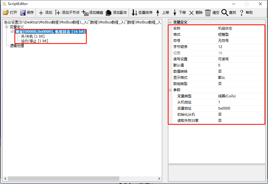
Create a "unit status" variable, set the variable type to "coil", add child nodes "on/off" and "run/stop", configure the variable address to 0x0000, and refer to the Modbus Basic Parameter Description for detailed settings, as shown below.
Screen configuration
Add a button control (Control ID: 1) to the screen. In the property panel of the button control, set the associated variable to "Unit Status/On/Off". The operation style of the button is a switch, as shown below

Run Preview
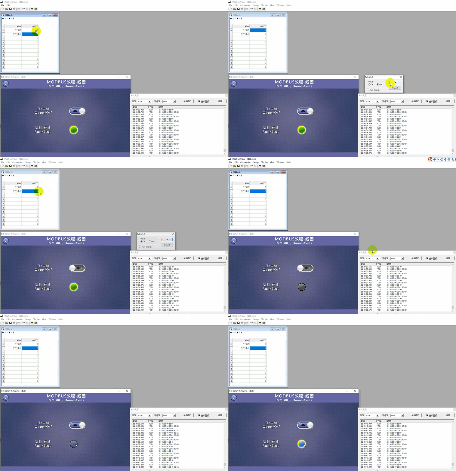
Through the above two steps, the button control with Control ID 1 is associated with the variable "Unit Status/On/Off". At this point, compile the project and run the virtual serial port screen, establishing a connection with the MODBUS Slave software. The button control displays the status of "Unit Status/On/Off". Simultaneously, clicking the button control changes the state of the variable "Unit Status/On/Off". Similarly, the button control with Control ID 2 is associated with the variable through the above method, achieving corresponding status display and control functions. As shown below
2.2 Discrete Input
The [Discrete Input] screen displays the status of the "discrete input" variable in the MODBUS protocol. The icon control is directly bound to the "discrete input" type of variable. The icon control will display the status of the variable, and when the value of the "discrete input" at that address changes, the icon control will correspondingly change
Variable Configuration
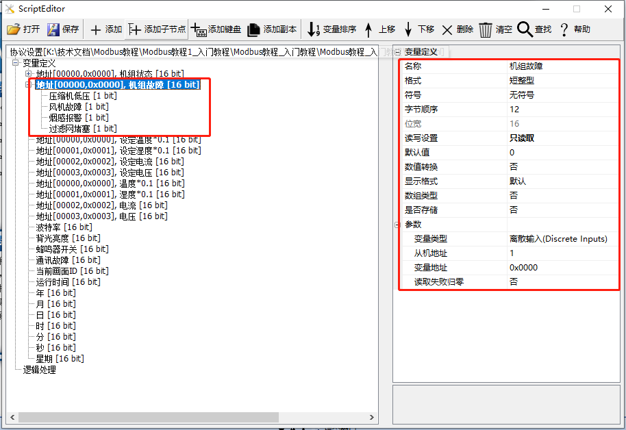
Add a variable: Create a "Unit Fault" variable, add a child node "Compressor Low Pressure", set the variable type to "Discrete Input", configure the variable address to 0x0000, and refer to the Modbus Basic Parameter Description for detailed settings, as shown below
Screen Configuration
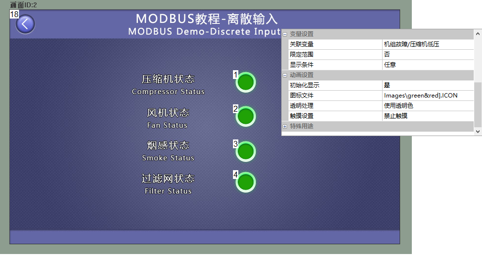
Add an icon control (Control ID: 1) to the screen. In the property panel of the icon control, set the associated variable to "Unit Fault/Compressor Low Pressure". Similarly, bind the icon controls with IDs 2 to 4 to their corresponding variables. Refer to the "Configuration Controls Tutorial - Icon Controls" for instructions on how to create, as shown below
Run Preview
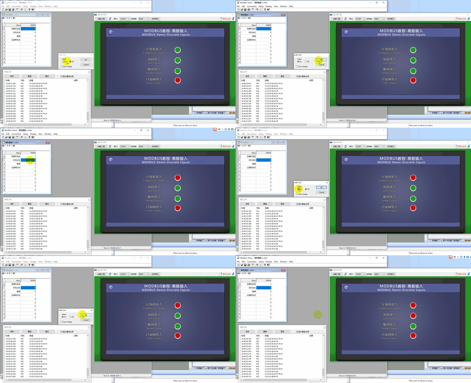
Through the above two steps, the icon control with Control ID 1 is associated with the variable "Unit Fault/Compressor Low Pressure". At this point, compile the project and run the virtual serial port screen, establishing a connection with the MODBUS Slave software. The icon control displays the status of the variable "Unit Fault/Compressor Low Pressure".
2.3 Maintain registers
The "Hold Register" screen directly displays the value of the "Hold Register" variable in the MODBUS protocol. The text control is directly bound to the "Hold Register" type variable. The text control will display the value of the variable. When the value of the "Hold Register" at this address changes, the text control will correspondingly change.
Variable Configuration
Add Variable: Create a "Set Temperature" variable, set the variable type to "Hold Register", and configure the variable address to 0x0000. If this variable represents temperature, and the slave transmits a value of 225℃ while the actual temperature is 22.50℃, then the scaling ratio between the actual value and the transmitted value is 0.1, and the offset value is 0. Therefore: Set "Value Conversion" to "Yes", "Scaling" to "0.1", and "Translation" to "0". For detailed setting instructions, refer to the Modbus Basic Parameter Description, as shown below.
Screen Configuration
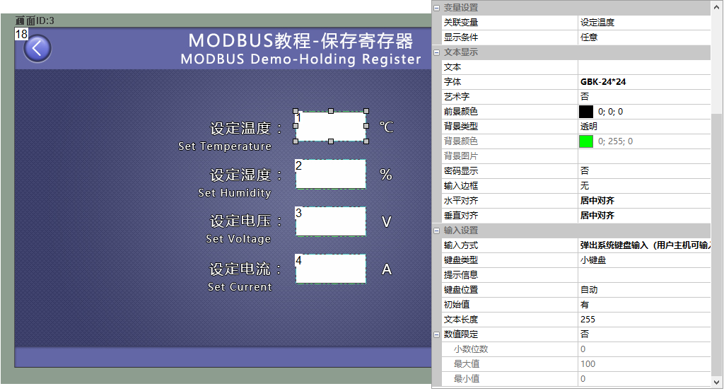
Add a text control (control ID: 1) to the screen, as shown in Figure 4-14. In the property panel of the text control, set the associated variable to "Set Temperature", and the input method to "Pop-up System Keyboard Input (user host can input)" mode, as shown below.
Run Preview
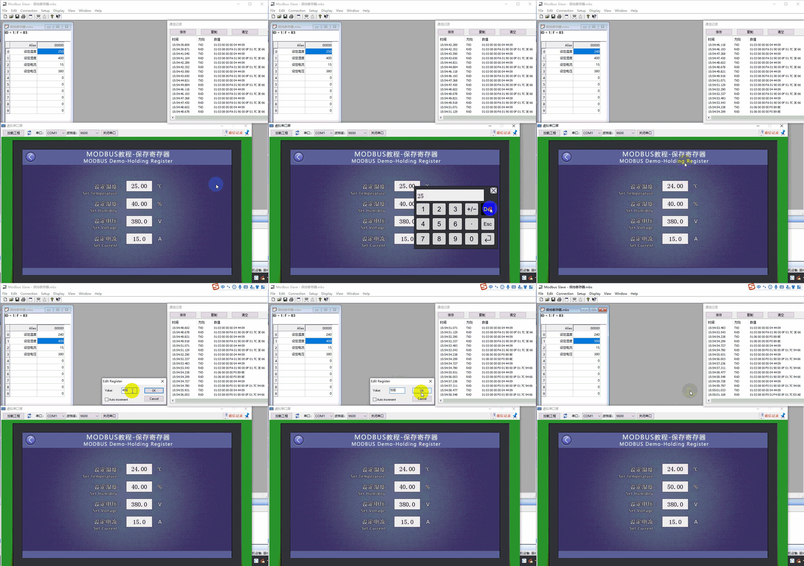
Through the above two steps, the text control with control ID 1 is associated with the variable "Set Temperature". At this point, compile the project and run the virtual serial port screen, establish a connection with the MODBUS Slave software, and the text control will display the value of the variable "Set Temperature". Click the text control to pop up the keyboard, where you can set the value of the variable "Set Temperature".
2.4 Input register
The [Input Register] screen directly displays the value of the "Input Register" variable in the MODBUS protocol. The text control is directly bound to a variable of type "Input Register", and the text control will display the value of the variable. When the value of the "Input Register" at that address changes, the text control will correspondingly change
Variable configuration
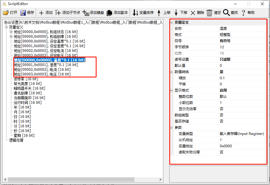
Create a "temperature" variable, set the variable type to "input register", and configure the variable address to 0x0000, as shown below
Screen configuration
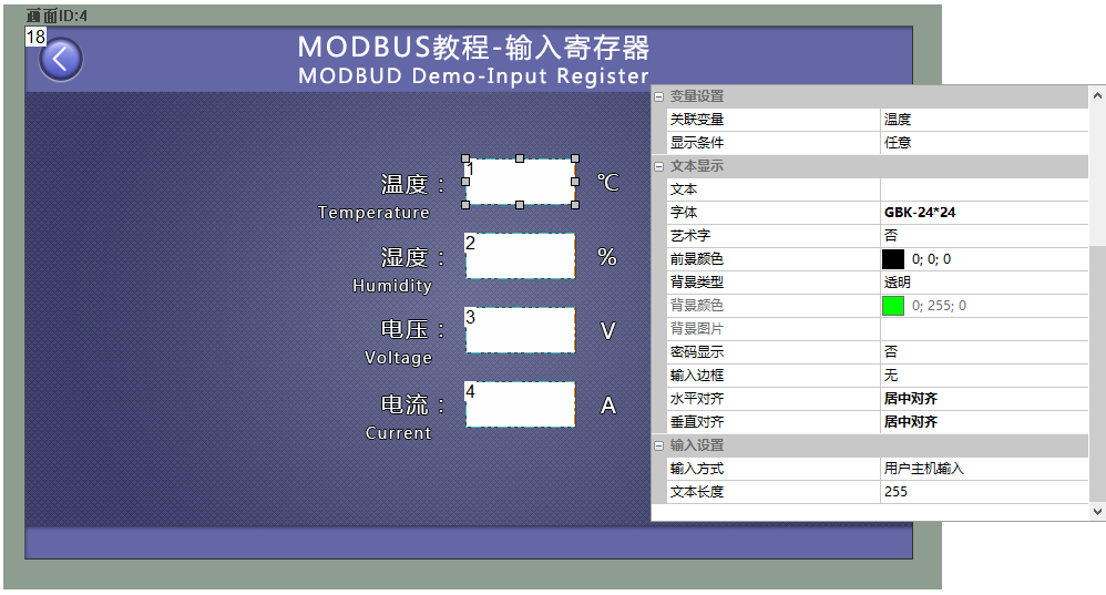
Add a text control (Control ID: 1) to the screen. In the property panel of the text control, set the associated variable to "temperature" as shown below
Run Preview
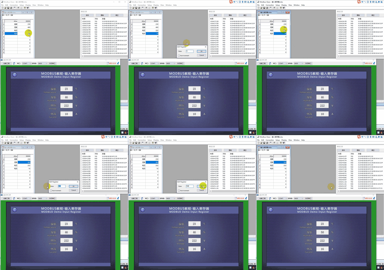
Through the above two steps, the text control with Control ID 1 is associated with the "temperature" at address 0x0000. At this point, compile the project and run the virtual serial port screen, establish a connection with the MODBUS Slave software, and the text control will display the value of the hold register at address 0x0000. Similarly, after associating the text controls with Control IDs 2, 3, and 4 with different variables through the above method, they can display the values of the corresponding addresses, as shown below
2.5 System Variables
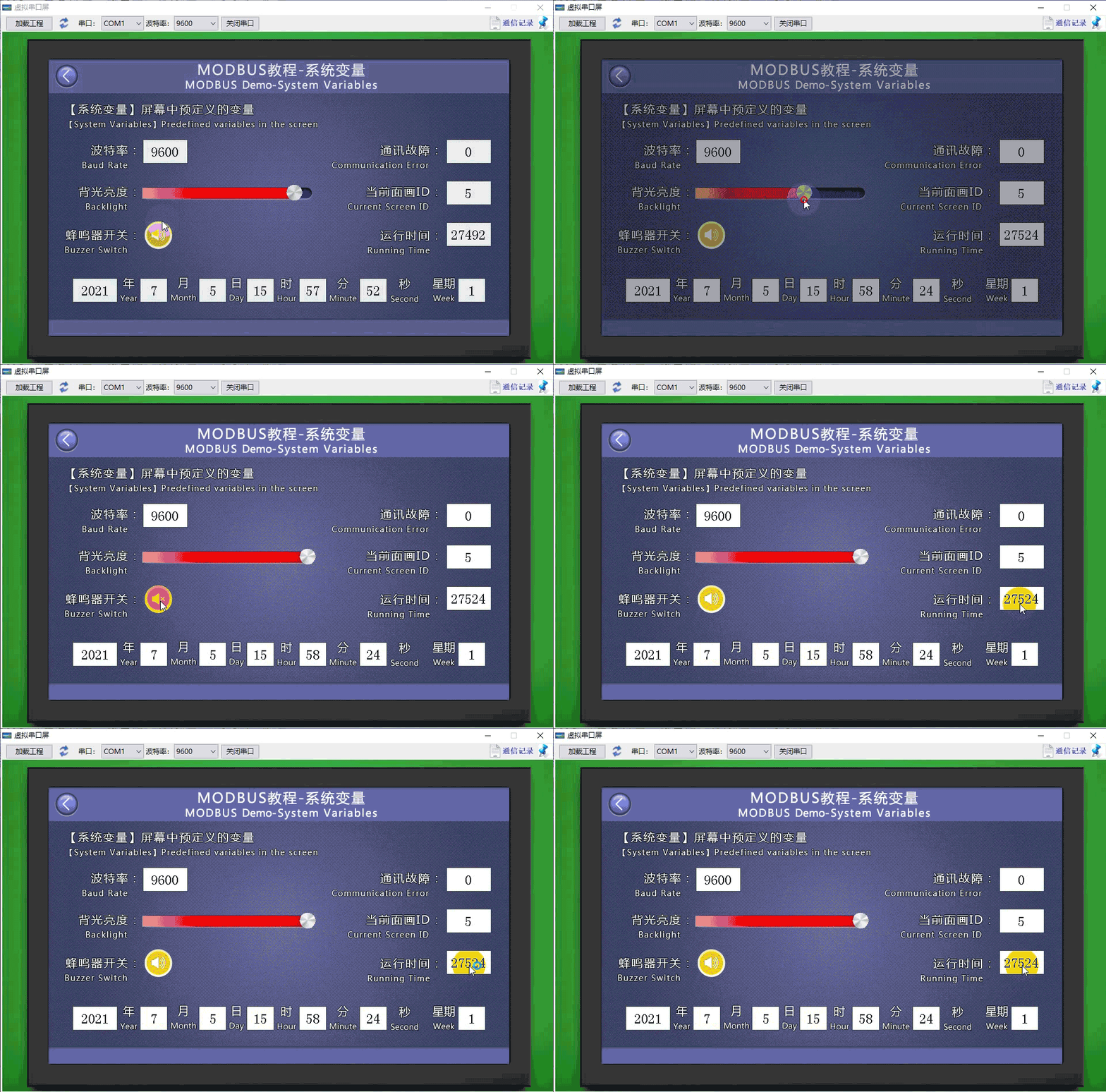
[System Variables] System variables are predefined variables in the system, facilitating direct access. These predefined variables on the screen include baud rate (readable), backlight brightness (readable and writable), buzzer switch (1 enables the buzzer, 0 disables it, readable and writable), communication fault (0 indicates normal, non-0 indicates fault, readable), current screen ID (readable and writable), running time (unit: minutes, readable), date (readable), etc
Variable Configuration
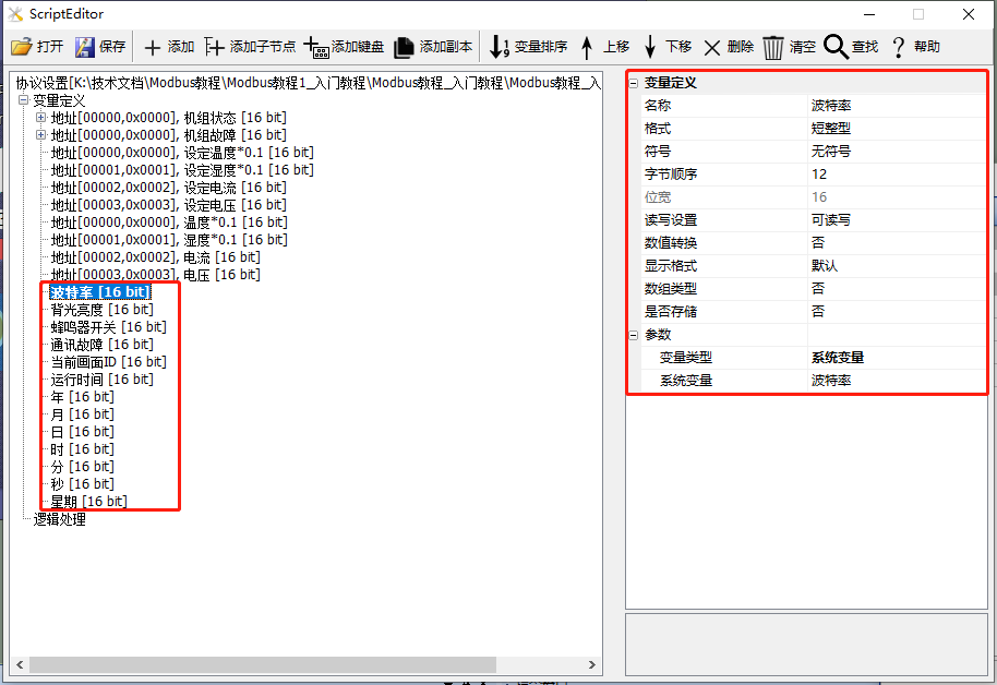
Add a variable: Create a "backlight brightness" variable, set the variable type to "System Variable", and set the system variable parameter to "backlight brightness". For detailed settings, refer to the Modbus Basic Parameter Description, as shown below
Screen Configuration
Add a progress bar control (Control ID: 2) and a slider control (Control ID: 3) to the screen. In the property panel of the progress bar control, set the sliding notification to "Associated Slider"; in the property panel of the slider control, set the associated variable to "backlight brightness". For specific applications of the slider control and progress bar control, refer to the Tutorial on Configuring Controls - Tutorial on Slider Control, as shown below
Run Preview
Through the above two steps, the slider control with Control ID 2 is associated with the memory variable "backlight brightness"; at this point, compile the project and run the virtual serial port screen. Sliding the cursor of the "Slider Control" can control the backlight brightness of the screen.


Leave a Reply