
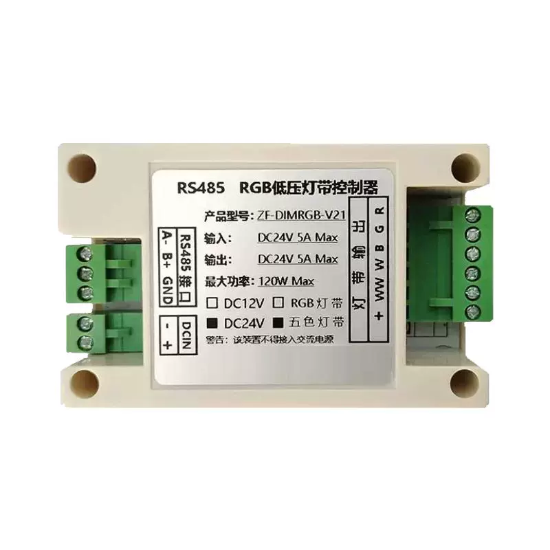
1. Product Introduction
The RGB strip dimmer is a digital linear dimming and color adjustment driver with low voltage and high precision grading. It supports five constant voltage outputs, low ripple without flicker, adjustable output current from 0-100%, and continuous dimming and color changing mode. This product is widely used in scenarios such as homes and commercial places that require adjusting the lighting atmosphere.
2, Product parameters
- NameRS-485 infinite dimming controller
- Input: DC12V~24V
- Output: DC12V/24V/120W
- Supported Protocols: RJ-45, Modnus Private Protocol (other protocols can be customized)
- Dimming Level: RGB/CW/0-100%
- Size: 96.5 *50* 32MM
- Maximum power: Single module 120W (expandable)
- Operating temperature: -10~50 ℃
- Other functions: Mode preset
III. Functional features
Non polarized dimming and color adjustment
- Infinite dimming brightnessSupports brightness adjustment from 0% to 100% to meet the brightness requirements of different scenes.
- Infinite color temperatureThe color temperature adjustment range is 3000K-6500K, which can achieve a smooth transition from warm light to cool light.
- Infinite color toneSupports RGB full-color adjustment, allowing for the mixing of any color by controlling the brightness of red, green, and blue.
Control method
- RS-485 interfaceSupport centralized control through RS-485 interface for easy integration with smart home systems.
- Modnus Private Protocol: Supports device communication and control through the Modnus protocol, ensuring the stability and security of data transmission.
Device Compatibility
- Monochrome LED Strip: Supports brightness adjustment and switching between cool and warm light for monochrome LED strips.
- RGB Color Light Strip: Supports color switching and brightness adjustment of RGB light strips, and can preset colors according to project requirements.
IV. Application Scenarios
RGB strip dimmer is suitable for various scenarios, including but not limited to:
- Home lighting: It achieves dimming and color adjustment of the entire house's lighting, creating a warm or bright atmosphere.
- Commercial venues: such as restaurants, hotels, shopping malls, etc., the lighting effects can be adjusted according to different time periods and activity needs.
- Entertainment venues: such as bars KTV, Cinemas, etc. enhance the atmosphere experience by dynamically adjusting the color and brightness of lighting.
V. Installation Guide
Hardware Installation
- Power Connection: Connect the input terminal of the dimmer to a DC12V~24V power supply.
- Light strip connection: Connect the output terminal of the RGB light strip to the corresponding output terminal of the dimmer.
- Communication Connection: Use an RJ-45 Ethernet cable to connect the RS-485 interface of the dimmer to the control host.
Software Configuration
- Device Identification: Identify the device ID of the dimmer by controlling the host.
- Parameter Settings: Set the communication parameters of the dimmer as needed (such as baud rate, parity, etc.).
- Scene Preset: Preset different lighting scenes on the control host, such as "Romantic Mode", "Working Mode", etc.
VI. Usage
Basic Operation
- Switch Control: Turn on or off the lights by sending control commands.
- Brightness Adjustment: Adjust the brightness value (0-100%) to change the brightness of the light.
- Color Temperature Adjustment: Change the color temperature of the light by adjusting the color temperature value (3000K-6500K).
- Color Adjustment: Change the color of the light by adjusting the RGB values (0-255).
Advanced Features
- Mode Switching: Switch between different lighting modes, such as "Romantic Mode", "Alarm Mode", etc.
- Data Save: Set whether to save configuration data so that it can be restored to its previous settings after device restart.
7. Protocol Description
Modnus Protocol Table (RGB Modbus RTU V1.2)
| Serial Number | Function Code | Register Address | Value | Function Description | Remarks |
|---|---|---|---|---|---|
| 1 | 6 | 0x0000 | arbitrary | Restart | |
| 2 | 3 or 6 | 0x0001 | 1~254 | Device ID | Default 1, force new ID number to use ID 0 |
| 3 | 3 or 6 | 0x0002 | 0~1 | 0: No response to data 1: Reply to data | Default 1 |
| 4 | 6 | 0x0003 | 0~3 | RS485 parameter settings: 0: RS485: 8, n, 1 1: RS485: 8, n, 2 2: RS485: 8, odd, 1 3: RS485: 8, even, 1 | Default 0, restart takes effect |
| 5 | 6 | 0x0004 | 1200~65535 | RS485 baud rate setting: where 65535 represents 115200, other values are the baud rate of that value | default 9600, restart takes effect |
| 6 | 3 or 6 | 0x0005 | 0~1 | 0: Do not save setting data 1: Save setting data | default 0, restart takes effect |
| 7 | 3 or 6 | 0x0100 | 1~3 | Control device type: 1: Monochrome light 2: Bicolor light 3: Tri color light | |
| 8 | 3 or 16 | 0x0101 | 0~n | Light mode: 0: No mode 1: Romantic mode (Tri color light) 2: Alarm mode 1- Red blue flashing (Tri color light) | Note: When using function code 16, the values of the 9 registers 0x0100~0x0108 must be set in one command at a time. |
| 9 | 3 or 16 | 0x0102 | 0~1 | 0: Turn off lights 1: Turn on lights | |
| 10 | 3 or 16 | 0x0103 | 0~100 | Brightness (monochrome, dual color, tri color) | |
| 11 | 3 or 16 | 0x0104 | 0~100 | Color temperature (dual color lamp) | |
| 12 | 3 or 16 | 0x0106 | 0~255 | R (three color lamp) | |
| 13 | 3 or 16 | 0x0107 | 0~255 | G (three color lamp) | |
| 14 | 3 or 16 | 0x0108 | 0~255 | B (Tri color Light) |
Communication Instruction Example
1. Restart (Function Code 6, Address 0x0000)
- •Example 1 (Restart Device):
01 06 00 00 00 00 89 CA- •
01: Device Address - •
06: Function Code 6 - •
00 00: Restart Register Address - •
00 00: Any Value (Here 0) - •
89 CA: CRC16 (Low Byte First)
- •
- •Example 2 (with non-zero restart):
01 06 00 00 12 34 84 BD- •
12 34: Any value (0x1234) - •
84 BD: CRC16
- •
2. Set device ID (function code 6, address 0x0001)
- •Example 1 (set ID to 10):
01 06 00 01 00 0A 58 0D- •
00 0A: New ID value (10) - •
58 0D: CRC16
- •
- •Example 2 (Force ID to 100):
00 06 00 01 00 64 D9 E1- •
00: Broadcast Address (Force Setting) - •
00 64: New ID Value (100) - •
D9 E1: CRC16
- •
3. Set Reply Data Mode (Function Code 6, Address 0x0002)
- •Example 1 (Disable Reply):
01 06 00 02 00 00 28 0A- •
00 00: Value=0 (No Reply) - •
28 0A: CRC16
- •
- •Example 2 (Enable Reply):
01 06 00 02 00 01 E9 CA- •
00 01: Value=1 (Reply Data) - •
E9 CA: CRC16
- •
4. Setting RS485 Parameters (Function Code 6, Address 0x0003)
- •Example 1 (8, odd, 1):
01 06 00 03 00 02 F8 0B- •
00 02: Value=2 (8, odd, 1) - •
F8 0B: CRC16
- •
- •Example 2 (8, n, 2):
01 06 00 03 00 01 B8 0A- •
00 01: Value=1 (8, n, 2) - •
B8 0A: CRC16
- •
5. Set RS485 baud rate (function code 6, address 0x0004)
- •Example 1 (57600 baud rate):
01 06 00 04 E1 00 5F 0D- •
E1 00: Value=57600 (0xE100) - •
5F 0D: CRC16
- •
- •Example 2 (38400 baud rate):
01 06 00 04 96 00 9F 8A- •
96 00: Value=38400 (0x9600) - •
9F 8A: CRC16
- •
6. Set the data saving mode (function code 6, address 0x0005)
- •Example 1 (Do not save settings):
01 06 00 05 00 00 A8 0B- •
00 00Value=0 (not saved) - •
A8 0B: CRC16
- •
- •Example 2 (Save Settings):
01 06 00 05 00 01 E8 0A- •
00 01Value=1 (Save) - •
E8 0A: CRC16
- •
7. Set device type (function code 6, address 0x0100)
- •Example 1 (Monochrome Lamp):
01 06 01 00 00 01 89 CA- •
00 01Value=1 (monochrome lamp) - •
89 CA: CRC16
- •
- •Example 2 (Two Color Lamp):
01 06 01 00 00 02 C8 0A- •
00 02Value=2 (dual color light) - •
C8 0A: CRC16
- •
Light control parameters (function code 16, address 0x0100-0x0108)
Example 1: Tri color light - alarm mode
复制01 10 01 00 00 09 12 00 03 00 02 00 01 00 64 00 00 00 00 FF 00 00 FF 00 3F 8A- •
01 10Address+Function Code 16 - •
01 00Starting address 0x0100 - •
00 09: 9 registers - •
1218 byte data - •Data:
- •
00 03Device type=3 (three color light) - •
00 02: Mode=2 (alarm mode) - •
00 01Switch=1 (turn on the light) - •
00 64Brightness=100% - •
00 00Color temperature=0 (ignored) - •
00 00Reserve=0 - •
FF 00: R=255 - •
00 00: G=0 - •
FF 00B=255 (red and blue flashing)
- •
- •
3F 8A: CRC16
Example 2: Dual Color Lamp - Custom Settings
复制01 10 01 00 00 09 12 00 02 00 00 00 01 00 50 00 64 00 00 00 00 00 00 00 00 1F 89- •Data:
- •
00 02Device type=2 (dual color light) - •
00 00: Mode=0 (no mode) - •
00 01Switch=1 (turn on the light) - •
00 50Brightness=80% - •
00 64Color temperature=100% (warm light) - •
00 00Reserve=0 - •
00 00R=0 (ignored) - •
00 00G=0 (ignored) - •
00 00B=0 (ignored)
- •
- •
1F 89: CRC16
Example of Individual Control (Function Code 6)
Light switch control (address 0x0102)
- •Turn on the lights:
01 06 01 02 00 01 68 0B- •
01 02Address 0x0102 - •
00 01Value=1 (turn on the light) - •
68 0B: CRC16
- •
- •Turn off the lights:
01 06 01 02 00 00 29 CB- •
00 00Value=0 (lights off) - •
29 CB: CRC16
- •
Brightness control (address 0x0103)
- •Brightness 30%:
01 06 01 03 00 1E 89 CC- •
00 1EValue=30 (30%) - •
89 CC: CRC16
- •
- •Brightness 100%:
01 06 01 03 00 64 48 0D- •
00 64Value=100% - •
48 0D: CRC16
- •
Color temperature control (dual color lamp) (address 0x0104)
- •Color temperature 30%:
01 06 01 04 00 1E 89 CC- •
00 1EValue=30 (30%) - •
89 CC: CRC16
- •
- •Color temperature 100%:
01 06 01 04 00 64 48 0D- •
00 64Value=100% - •
48 0D: CRC16
- •
RGB control (special for three color lights)
- •Set red:
01 06 01 06 00 FF 08 0C- •
01 06Address 0x0106 (R) - •
00 FFValue=255 (maximum red) - •
08 0C: CRC16
- •
- •Set green:
01 06 01 07 00 80 49 CD- •
01 07Address 0x0107 (G) - •
00 80Value=128 (50% green) - •
49 CD: CRC16
- •
- •Set Blue:
01 06 01 08 00 00 28 0D- •
01 08Address 0x0108 (B) - •
00 00Value=0 (no blue - off) - •
28 0D: CRC16
- •
Precautions for use
- 1.Device Address SettingBroadcast address is 0, used to send instructions to all devices
- 2.Data savingAfter modifying the configuration parameters, a save command must be sent to power off the memory
- 3.Transition time: Unit in milliseconds, affecting the smoothness of brightness changes
- 4.Mode switchingSwitching the working mode will overwrite the current manual brightness setting
- 5.CRC verificationAll instructions must contain the correct CRC checksum
8, Troubleshooting
- The light is not onCheck if the power connection is normal and confirm if the dimmer has received the control command.
- color abnormalityCheck if the RGB values are set correctly and confirm if the light strip connection is loose.
- Communication Failure: Check if the RS-485 communication line is connected correctly and confirm if the baud rate and checksum settings match.
9. Warranty Information
- Warranty Period: Within 12 months from the date of purchase.
- Warranty Scope: Malfunctions or performance issues that occur during normal use of the product.
- Warranty Conditions: Purchase proof is required, and human damage or improper use is not covered by the warranty.


Leave a Reply