
OneEquipment Overview and Principle
The fully automatic sediment online monitoring system mainly consists of sediment sensors, data acquisition and transmission systems (including RTUs), power supply systems, data management software, and installation brackets.
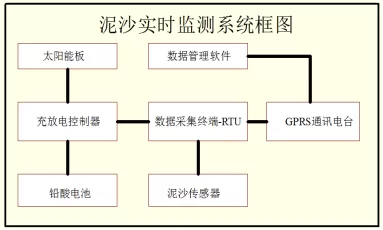
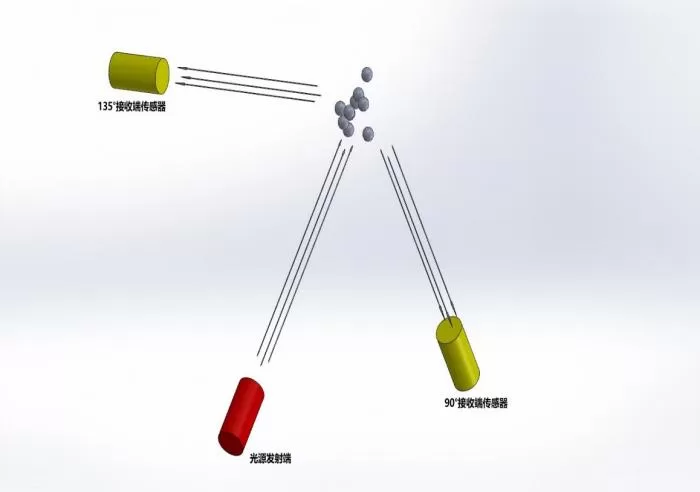
The sand sensor is based on the combined infrared absorption scattering method, and the ISO7027 method can be used to continuously and accurately measure the concentration of suspended solids. According to ISO7027 infrared double scattering light technology, suspended solids concentration values are determined without being affected by chromaticity. By establishing a correlation between suspended solids concentration values and sediment content, sediment content data can be directly output, achieving real-time online monitoring. According to the usage environment, it can be optionally equipped with self-cleaning function and protective device.
Two, Equipment Installation
1. Installation Site Selection
Before installing the fully automatic sediment online monitoring system, it is necessary to conduct an analysis of the water and sediment characteristics of the monitoring station over the years, understand the characteristics of cross-section erosion and deposition, changes in river regime, and floating debris in floods, and select the optimal installation location and method for the system. Priority should be given to selecting a vertical line with good representativeness of sediment concentration. After the vertical line is determined, priority should be given to selecting measurement points with good representativeness of sediment concentration.
- Installation precautions
- The sensor should be placed at least 50cm underwater, and the sensor should not be placed in the air for a long time to collect data. The placement of
- sensors should strive to ensure stable flow conditions without significant turbulence or disturbances.
- Sensors generally use side view measurement, and the instrument needs to be horizontally fixed during installation, with the sensor facing downstream for data collection. The sensor layout should be arranged at one or more representative points on the test river section according to the specifications. When installing the sensor, try to avoid floating objects and other damage to the sensor as much as possible.
- The placement of sensors needs to be arranged according to the specifications at one or more representative points on the test river section.
- Try to avoid floating objects and other damage to the sensor during installation.
- Installation Method
The measurement principle of the fully automatic sediment online monitoring system is to calculate the average sediment concentration of the section based on the single point sediment break rate relationship. Therefore, it must be installed at a representative point or multiple points on the vertical line of the test river section according to the specifications. The sediment sensor is for side view measurement, and the instrument needs to be fixed horizontally and vertically during installation (with the sensor facing downstream). In order to ensure that the sensor can still measure in real time at low water levels, the installation depth should be lower than the lowest water level. The instrument will measure the sediment concentration of the river at a fixed location, and the impact of floating debris on the instrument should be considered during installation. The installation methods of the fully automatic sediment online monitoring system include: self recording well wall, bridge pier, wharf, and measuring ship installation, construction of cast-in-place piles if there is no fixed carrier on site, installation of suspended floating boats with cyclic cables, and installation of shore guide rail brackets.
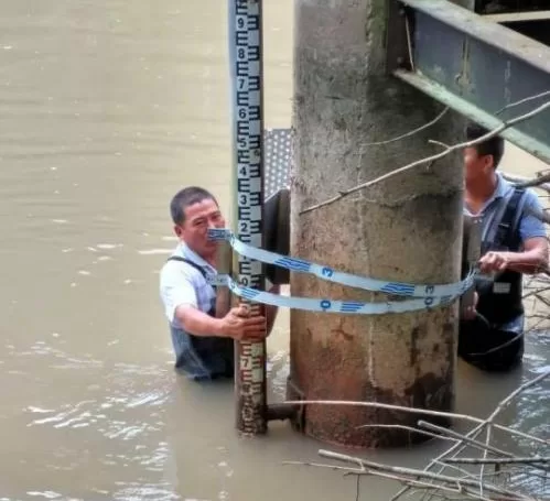
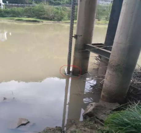
The installation methods of the fully automatic sediment online monitoring system include: self recording well wall, bridge pier, wharf, and measuring ship installation. If there is no fixed carrier on site, it can be installed with cast-in-place piles, suspended floating boats, and shore guide rail brackets.
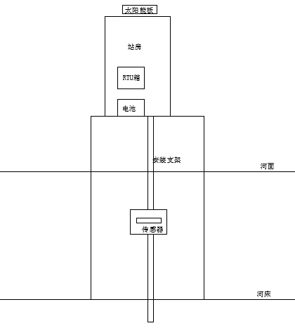
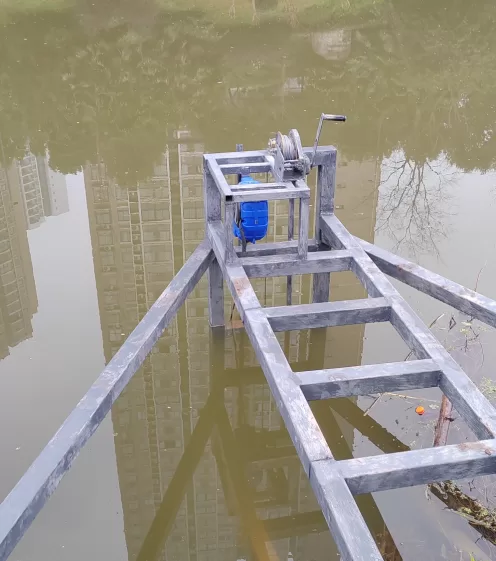
Type 1: Fixed bracket installation
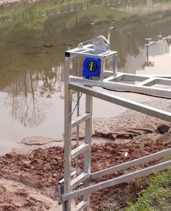
This installation is generally applied to shallow and narrow river channels, where fixed brackets are installed along the river and sediment sensors are mounted on the brackets.
Type 2: Floating Platform Installation
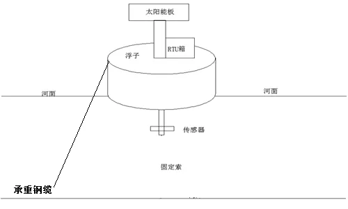
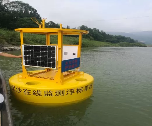
Generally used in wider and deeper rivers, sediment sensors are installed at the center of the river, and brackets are installed under the float. The sensor is fixed on the bracket, and the float is fixed on the riverbed with steel cables. This post is relatively complex and can measure sediment content at a fixed depth.
Bracket Design and Anti theft Measures
Customize brackets suitable for installation based on on-site conditions.
Generally, bracket design:
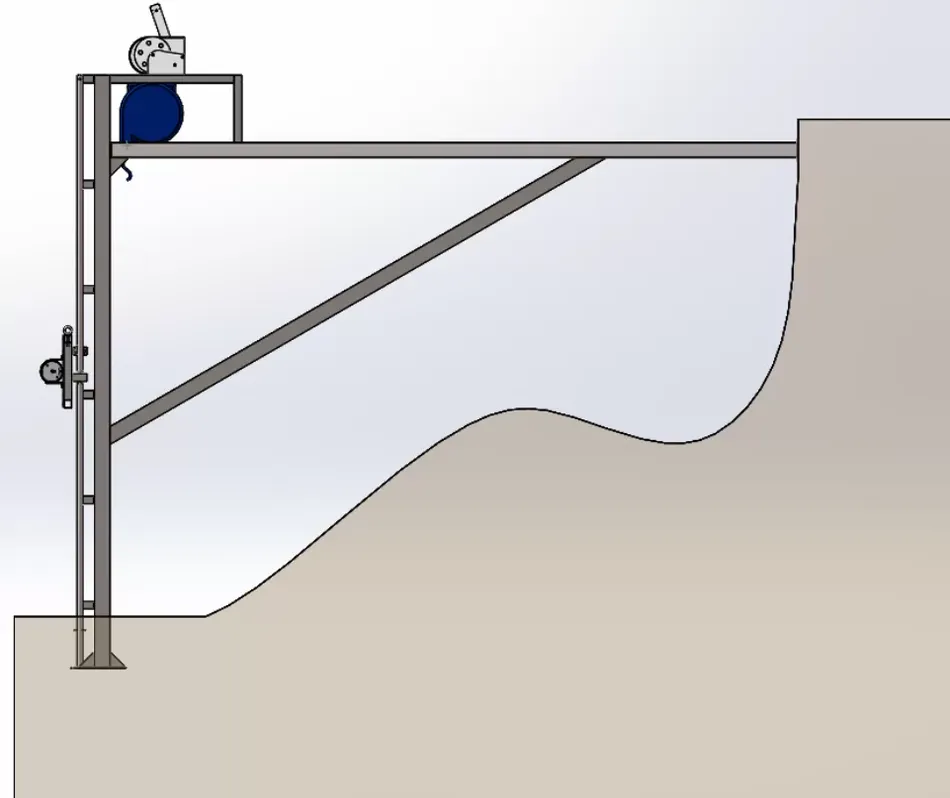
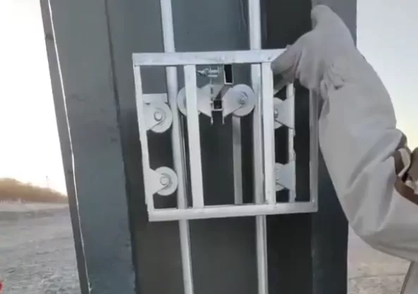
The overall bracket guide rail is made of 316 stainless steel material, and the sliding part is made of 316 stainless steel material. The transmission pulley is tightly attached to the guide rail; The lower end of the guide rail adopts a limit and the upper end adopts a limit and is designed with an anti-theft lock. The lower part prevents the sliding bracket and sensor from coming into contact with the bottom mud, and the upper part prevents personnel from directly taking out the sliding bracket and sensor or engaging in destructive theft behavior; The sliding bracket is connected to the winch as a whole; If there is a ball machine on site, it can be connected to the system to check the equipment status at any time,Prevent malicious destruction and theft of equipment, etc.
Probe fixation
The sediment sensor comes with a simple installation bracket when it leaves the factory, and the on-site requirements are met by pouring a fixed base or equipment installation bracket according to the site situation. The equipment installation bracket can use a 32 diameter galvanized round pipe and bend it with a flat iron. The bent flat iron is welded to the galvanized round pipe on one side and fixed to the self measuring well or bridge pier or pouring base on the other side with expansion screws. The sensor was originally intended to be fixed to the built-in simple bracket with an adaptive clamp, and then the sensor bracket was fixed to the on-site sliding bracket. After this part is fixed, the sliding bracket is installed on the galvanized round pipe, and the fixed round pipe serves as the guide rail for the sliding bracket. After the sliding bracket is fixed, and on-site testing is conducted to see if it can slide normally, the connecting cable is fixed to the winch, Facilitating the lifting operation of the entire sensor through the winch in the later stage, the equipment box is fixed to the designated position with expansion screws.
Sliding bracket
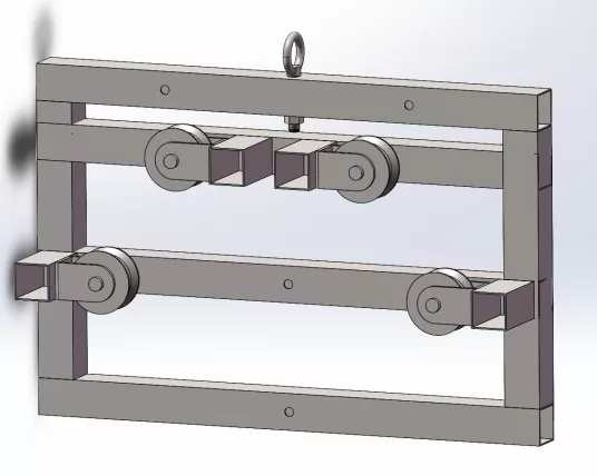
Components of the bracket
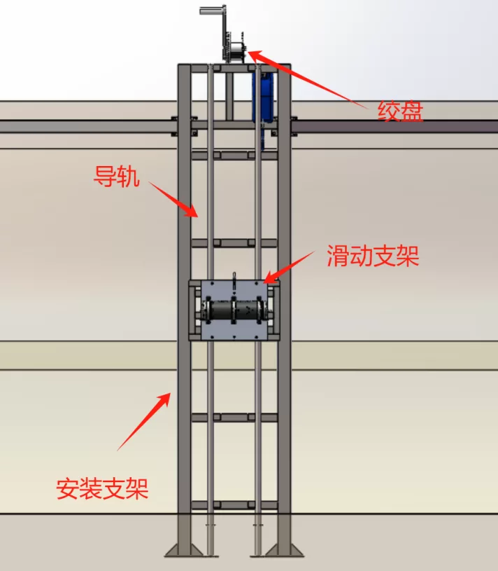
On site installation diagram
threeEquipment debugging
Power supply system connection
1. The solar panel is connected using a two core power cord. Thread the power cord out of the wiring hole of the installation tube, open the black plastic box under the solar panel, there are two terminal posts inside, and the right terminal post is connected to the red cable of the+pole and dual core wire; The terminal on the left is connected to a white cable with one pole and two core wires. When wiring, strip the two core cables by 20mm, fold them in half, and twist them into strands. Insert them into the two wiring holes of commonly used signaling components in the wiring socket, tighten them with screws, and finally fix the black plastic sealing box with screws and seal it with sealant.
2. Fix the solar panel bracket onto the solar panel using M6 bolts.
3. Fix the solar panel with connected wires and fixed brackets on the upright pole (if the solar panel is installed in the station building position, use screws to fix it)
4. Fix the charging controller on the installation base plate, and connect the solar cell, battery, and electrical appliance (RTU) to the corresponding wiring terminals according to the instructions. Tighten the screws to avoid poor contact.
5. Connect the battery to the charging controller, with the red wire connected to the positive pole and the black wire connected to the negative pole. After fixing the connection, place the battery into the equipment box.
RTU equipment box line connection
1. Connect the RTU power cable to the output terminal of the solar controller.
2. Connect the signal line of the sediment sensor and the on-site water level gauge to the RTU and fix them in place.
3. After checking and confirming that all types of cables are connected correctly, turn on the power switch of the equipment box and power up the equipment.
After the device is powered on and self checks normally, set the operating parameters of the RTU according to the requirements.
After the parameter settings are completed, the testing work can be carried out.
software configuration
Mainly configure site related information, as well as some operating parameters and channel parameters. To use this software, you need to connect the RS232 cable to the interface connected to the GPRS module. At this time, GPRS is not connected. Use the PC debugging assistant to configure the parameters:
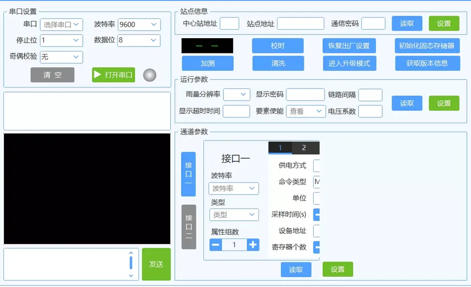
(1) Station Information
. This column can be used to configure station related content. Click Read to obtain the current station information. After editing, click Settings and wait for successful settings.
(2) Operating Parameters
are mainly used to configure some parameters during machine operation. The display password is the screen password, the link interval is the heartbeat interval, the display timeout is how long the screen has not been operated before automatically shutting down, and the voltage coefficient is the voltage correction value used for voltage correction.
(3) Channel Parameters
This parameter is mainly used to configure sensor equipment, and the positions of interface one and interface two are marked in the wiring diagram;
The baud rate is the device communication baud rate, and the sediment sensor defaults to 9600;
type uses interface communication method, and the sediment sensor defaults to RS485;
has 2 attribute groups for collecting sediment content and depth information.
Click on the top left corner 1 and set the number of groups to 1:
This is the sediment equipment configuration:
Power supply mode: default intermittent power supply is sufficient;
Bind power supply name: Set as power supply 4 for interface 2;
Command type: The command type for sediment sensor is MODBUS;
Peripheral device type: silt;
Unit: sediment;
Peripheral working mode: master-slave mode;
Sampling time: Depending on the actual situation, not less than 5 seconds;
Peripheral protocol: Modbus;
Equipment Address: 01;
Device Address Function Code: 0x03;
Number of registers: 2;
Register Address 0002;
RTU Local Screen Control
This interface is the default main interface of the chassis screen, which includes site information, measurement information, system status, etc. Green indicates normal or enabled, and red indicates abnormal device operation.
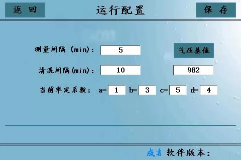
This interface mainly configures some operating parameters. If different water level intervals are set, the interface sets the operating parameters at the current water level. The air pressure base value is specific to the water depth equipment. If it is not equipped, it should not be modified. If it is equipped, it can be modified in two ways: 1. Click the text box directly, enter the base value, and click the air pressure base value; At this time, the sediment equipment should be placed in the air, and after modifying the parameters, click save. In addition to on-site configuration, the sediment equipment can also be remotely configured, remotely telemetry and data management, and remotely upgraded through backend software. The software platform is configured with various reports that meet the requirements of the specifications, meeting the requirements of hydrological monitoring and compilation.
In addition to on-site configuration, remote configuration, remote telemetry, data management, and remote upgrades of sediment equipment can also be performed through backend software. The software platform is configured with various reports that meet the requirements of the specifications, meeting the requirements of hydrological monitoring and compilation.
Software login interface
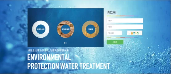
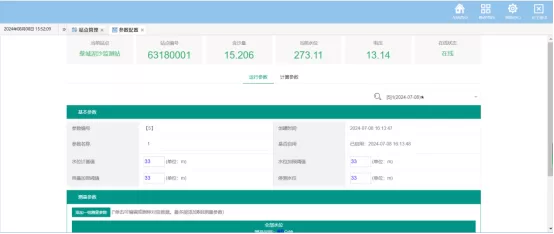
Parameter Configuration Interface for Sedimentation Equipment
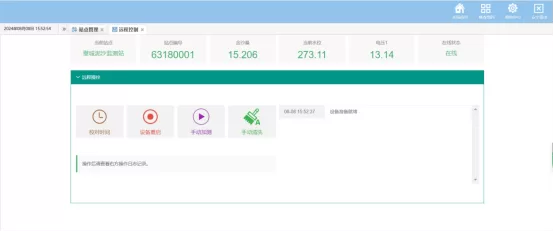
Remote Control Interface for Sedimentation
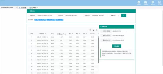
Sedimentation Data (Display Sensor Maximum, Minimum, Intermediate, and Average Data)
Sedimentation Process Line
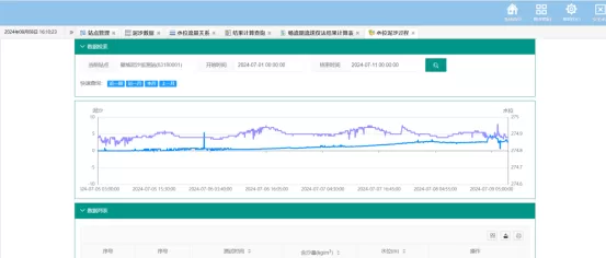
Water Level Flow Process Line
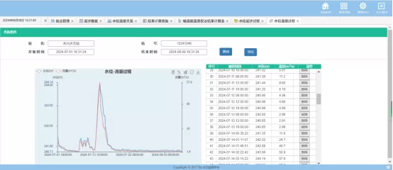
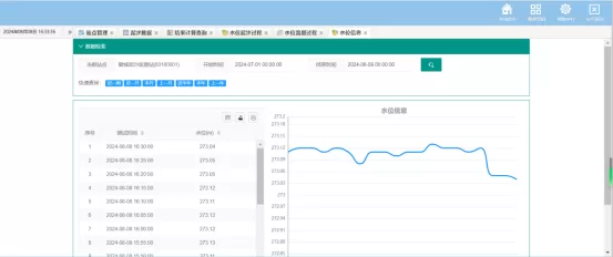
Water Level Process Line
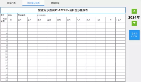
Daily Average Sediment Content Table
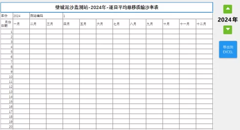
Daily Average Suspended Sediment Transport Rate Table
System Acceptance
Functional Acceptance. Confirm that the fully automatic sediment online monitoring system meets all the technical performance requirements of the equipment in this project.
Performance acceptance. Evaluate the performance of the fully automatic sediment online monitoring system, including measurement accuracy, stability, and reliability.
Regular Maintenance
In order to achieve the best measurement results, regular maintenance and upkeep are necessary. Maintenance and upkeep mainly include cleaning the sediment monitoring device, checking if the sediment monitoring device is damaged, etc. During maintenance and testing, the relevant status of the sediment monitoring instrument can also be viewed.
It is generally recommended to maintain sediment sensors at least once every 3 months (with an appropriate increase in frequency depending on water quality). The main maintenance tasks include:
(1) Check the sediment monitoring device, inspect and clean the sediment monitoring device, including whether there are signs of collision, whether there is damage, and the condition of surface attachments on the sediment monitoring device.
(2) Check the installation bracket, including whether it is stable, whether it is corroded, whether the screws are tightened, etc.
(3) Check if the power supply system is working properly.
(4) Check if the device communication is normal.
(5) Check the cable interface, including whether the interface is intact, the sealing of the interface, etc.
Training Outline for Fully Automatic Sediment Online Monitoring System
| Course Theme | Course Outline | Teaching Hours (Hours) |
| Fully Automatic Sediment Online Monitoring System | (1) Basic knowledge of fully automatic sediment online monitoring system: Introduce the characteristics, principles, application scenarios, etc. of the equipment. | 1.5 |
| (2) Basic operation of the fully automatic sediment online monitoring system on site. | 2 | |
| (3) The basic functions and abnormal handling of the entire automatic sediment online monitoring system. | 2 | |
| (4) System maintenance and upkeep: Introduce how to correctly maintain and upkeep the fully automatic sediment online monitoring system, including regular inspections, dust cleaning, component replacement, etc. | 4 | |
| (5) Course Summary and Q&A: Summarize the course content, answer students' questions, and provide corresponding operational guidance and suggestions. | 2 |
Installation and commissioning records
| Inspection items | Inspection content | Inspection results |
| Voltage fluctuation | Voltage fluctuation: DC 12v power supply, allowable voltage fluctuation range: -15%~20% | |
| Sedimentation sensor | Water seepage test | |
| Data reading | ||
| Main control unit | Communicate with the upper computer | |
| Equipment boost status | ||
| Operating parameter settings | ||
| Equipment parameter settings | ||
| Water depth data acquisition | ||
| Sedimentation data acquisition | ||
| Power supply unit | Battery charging and discharging | |
| Solar energy (charger)/mains charging | ||
| Appearance | The surfaces of each component should be smooth, the coating should be uniform, and there should be no rust or peeling. The welding of the welded parts should be uniform, smooth, and free of porosity and leakage. The equipment is free from deformation and securely installed. 4. Whether the connections of the product are stable and whether the screws are missing. | |
| Final judgment result | ||
| Remarks | ||


Leave a Reply