
PLC Programming Core Concepts: Analysis of Switching, Analog, and Pulse Values
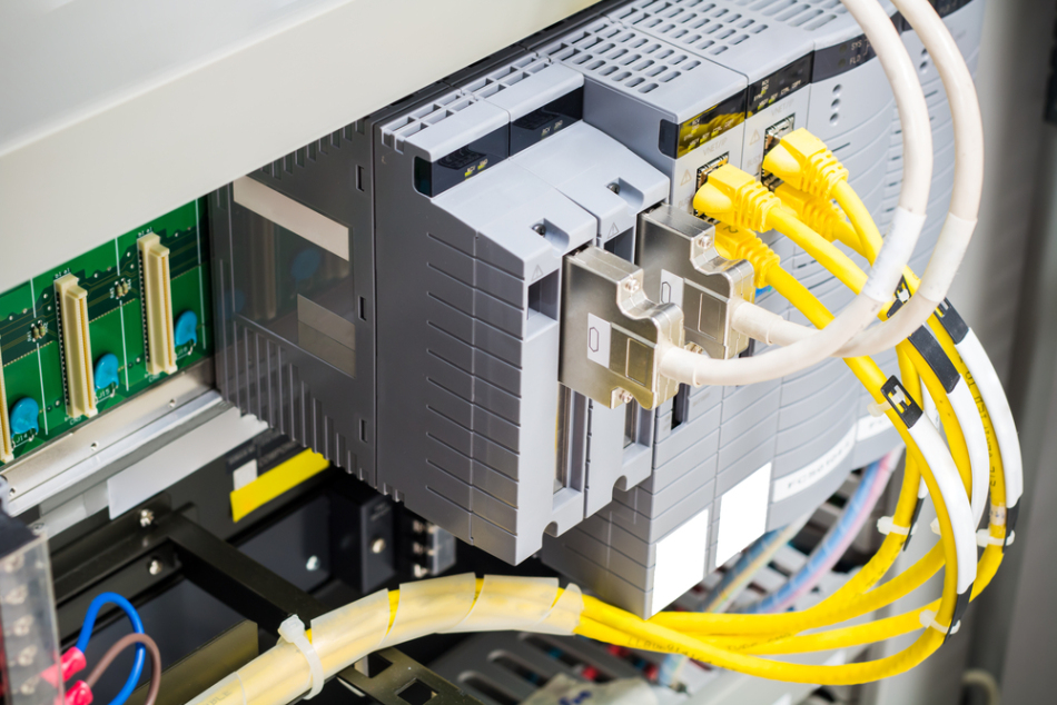
In PLC programming, switching, analog, and pulse values are three fundamental concepts. A deep understanding of these three concepts is key to mastering PLC skills.
- Switching Value (or Logic Value):
- Switching values are binary, meaning they have only two states: 0 (OFF) and 1 (ON).
- Sequential control is a basic application of switching values, which generates specific outputs based on the historical and current states of inputs.
- Control modes can be manual, semi-automatic, or fully automatic, and control principles can be decentralized, centralized, or hybrid.
2.Analog Value:
- Analog values represent continuously changing physical quantities such as voltage, current, and temperature.
- Analog values can be converted to digital values, which are essentially multi-state switching values. Therefore, PLCs can reliably process converted analog values.
- Analog values are common in continuous production, hence referred to as process control.
- Non-standard analog values need to be converted to standard electrical signals such as 4-20mA or 0-10V.
- PLCs internally involve the conversion and calculation between analog and digital values. For example, a PLC analog unit with a resolution of 1/32767 corresponds to a temperature range of 0-100℃ for a 0-10V electrical quantity. Therefore, 0-32767 corresponds to 0-100℃, which means 1℃ corresponds to approximately 327.67 units. To achieve an accuracy of 0.1℃, the value needs to be further subdivided.
- Analog control methods include feedback, feedforward, proportional, and fuzzy control, among others.
3.Pulse quantity:
- Pulse quantity is a digital quantity, with its value alternating between 0 and 1.
- Pulse quantity in PLC is mainly used for position, motion, and trajectory control. For example, if a stepper motor driver has a resolution of 10,000 pulses per revolution, and the stepper motor needs to rotate 90 degrees, the number of pulses is (10,000 times frac{90}{360} = 2,500).
Conversion and processing of analog quantity:
- Overview: Analog quantity represents continuous variables in the physical world, such as voltage, current, pressure, and temperature. For PLCs, it is crucial to convert and process these quantities correctly.
- Conversion example: Assume that a PLC analog input unit has a resolution of 1/32767 and corresponds to a voltage range of 0-10V. This means that it can read a temperature range of 0-100℃. Therefore, the numerical range of 0-32767 corresponds to the temperature range of 0-100℃. Furthermore, the value corresponding to 1℃ is approximately 327.67. To improve accuracy to 0.1℃, simply divide 327.67 by 10.
- Control strategy: Strategies for analog quantity control include feedback control, feedforward control, proportional control, and fuzzy control.
2. Pulse quantity:
- Overview: Pulse quantity is a digital signal whose value alternates between 0 (low state) and 1 (high state). Its change speed (i.e., the number of pulse changes per second) is called frequency.
- Application: Pulse quantities processed by PLCs are mainly used for position control, speed control, and trajectory control. For example, a stepper motor needs to know the number of pulses for angle control. If the stepper motor driver specifies 10,000 pulses per revolution, then to rotate the stepper motor by 90 degrees, the required number of pulses is 2,500.
3. Detailed calculation of analog quantity:
Based on different voltage and current ranges, as well as different resolutions, analog quantities can be converted to specific hexadecimal values. For example:
- For a voltage range of -10V to 10V, at a resolution of 6000, the conversion result is F448—0BB8Hex; while at a resolution of 12000, the result is E890—1770Hex.
The above is only a brief overview. The specific conversion and processing methods vary depending on the model and specifications of the PLC, as well as the characteristics of the measured physical quantity.
Note: When inputting analog signals, attention should be paid to the wiring requirements to ensure the accuracy and stability of the signal.
Conversion between analog quantity and hexadecimal value:
- -10V to 10V voltage range:
- At a resolution of 6000, the conversion range is F448—0BB8Hex, with a corresponding numerical range of -3000—3000.
- At a resolution of 12000, the conversion range is E890—1770Hex, with a corresponding numerical range of -6000—6000.
- Voltage range from 0V to 10V:
- At a resolution of 12000, the conversion range is 0—1770Hex, with a corresponding numerical range of 0—6000.
- At the same resolution of 12000, the conversion range is 0—2EE0Hex, with a corresponding numerical range of 0—12000.
- Current range from 0mA to 20mA:
- At a resolution of 6000, the conversion range is 0—1770Hex, with a corresponding numerical range of 0—6000.
- At a resolution of 12000, the conversion range is 0—2EE0Hex, with a corresponding numerical range of 0—12000.
- Current range from 4mA to 20mA:
- At a resolution of 6000, the conversion range is 0—1770Hex, with a corresponding numerical range of 0—6000.
- At a resolution of 12000, the conversion range is 0—2EE0Hex, with a corresponding numerical range of 0—12000.
Please note that the above conversions may vary depending on the PLC model and configuration. Ensure to adjust according to specific specifications.
Analog input wiring requirements:
- Use shielded twisted-pair cables, but do not connect the shielding layer.
- If the input is not used, short-circuit the V IN and COM terminals.
- Ensure that the analog signal line is isolated from the main power lines (such as AC power lines, high-voltage lines).
- If there is interference on the power lines, add a filter between the input module and the power module.
- Before connecting the load power supply, first ensure that the CPU module is powered on.
- When powering off, first disconnect the load power supply, and then disconnect the CPU module power supply.
PLC programming algorithm (3) - Pulse control calculation
Pulse control is mainly used in PLC programming for angle, distance, and position control of drive devices such as stepper motors and servo motors. Below, we will take the stepper motor as an example to explore its control strategy in depth.
- Angle control:
- To achieve precise control, first determine the number of steps and the total number of pulses required per step for the stepper motor.
- The core of angle control is to convert the required angle to the corresponding number of pulses.
- The formula is expressed as:
[ text{Number of pulses}{text{Angle}} = text{Number of pulses}{text{Total}} times left(frac{text{Set angle}}{360°}right) ]
- Distance control:
- determines the total number of pulses required per revolution of the stepper motor.
- Furthermore, the diameter of the stepper motor's roller is considered to calculate the circumference of the roller.
- Based on the circumference and the total number of pulses, the moving distance represented by each pulse can be determined.
- The formula is expressed as:
[ text{Number of pulses}{text{Distance}} = frac{text{Set distance}}{left(frac{text{Roller diameter} times pi}{text{Number of pulses}{text{Total}}}right)} ]
- Position control:
- Position control is essentially a combination of angle and distance control, ensuring that the stepper motor reaches the predetermined position.
It should be noted that although the control logic of servo motors is similar to that of stepper motors, we also need to consider the internal electronic gear ratio of the servo motor and its reduction ratio with the external mechanical system.


Leave a Reply