
Modbus-related product recommendation:peidianxiang.taobao.com
Software usage
Manual connection
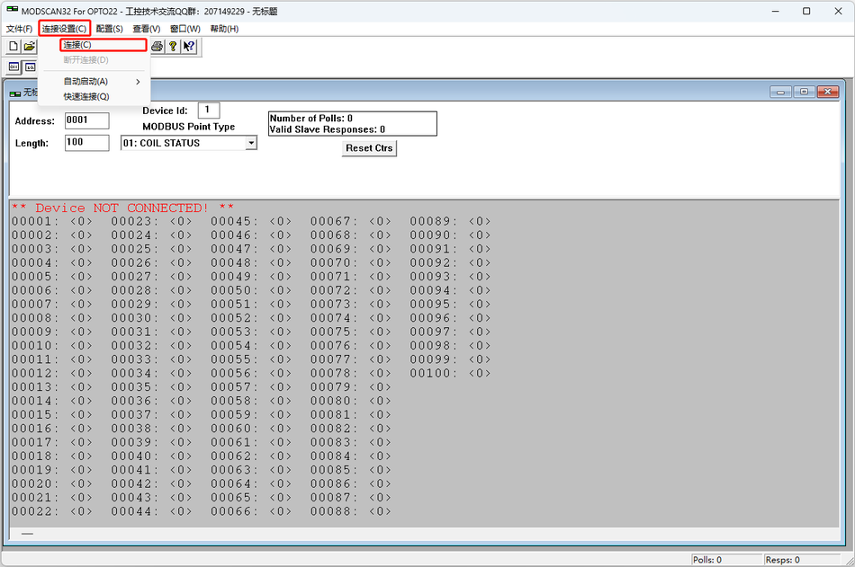
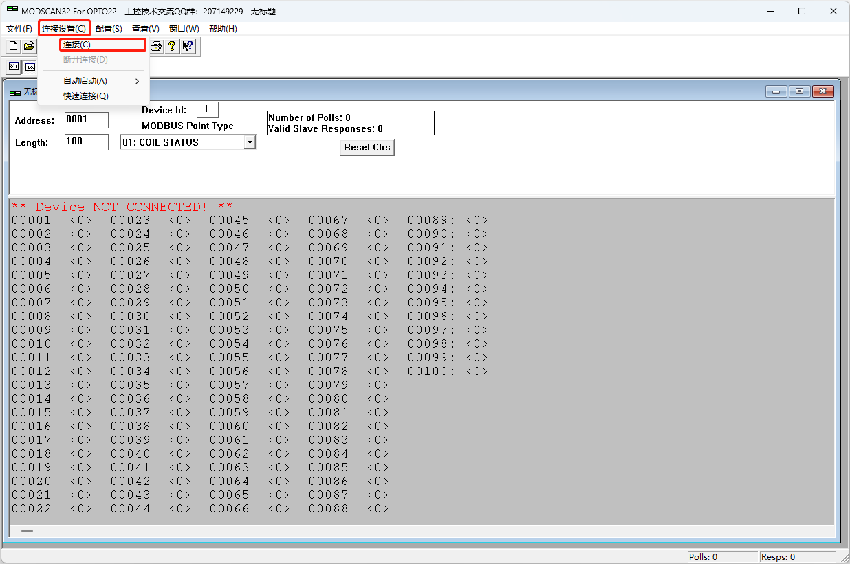
Click on the menu bar "Connection Settings (Connection)" -> "Connect (Connect)", and the connection configuration window will pop up.
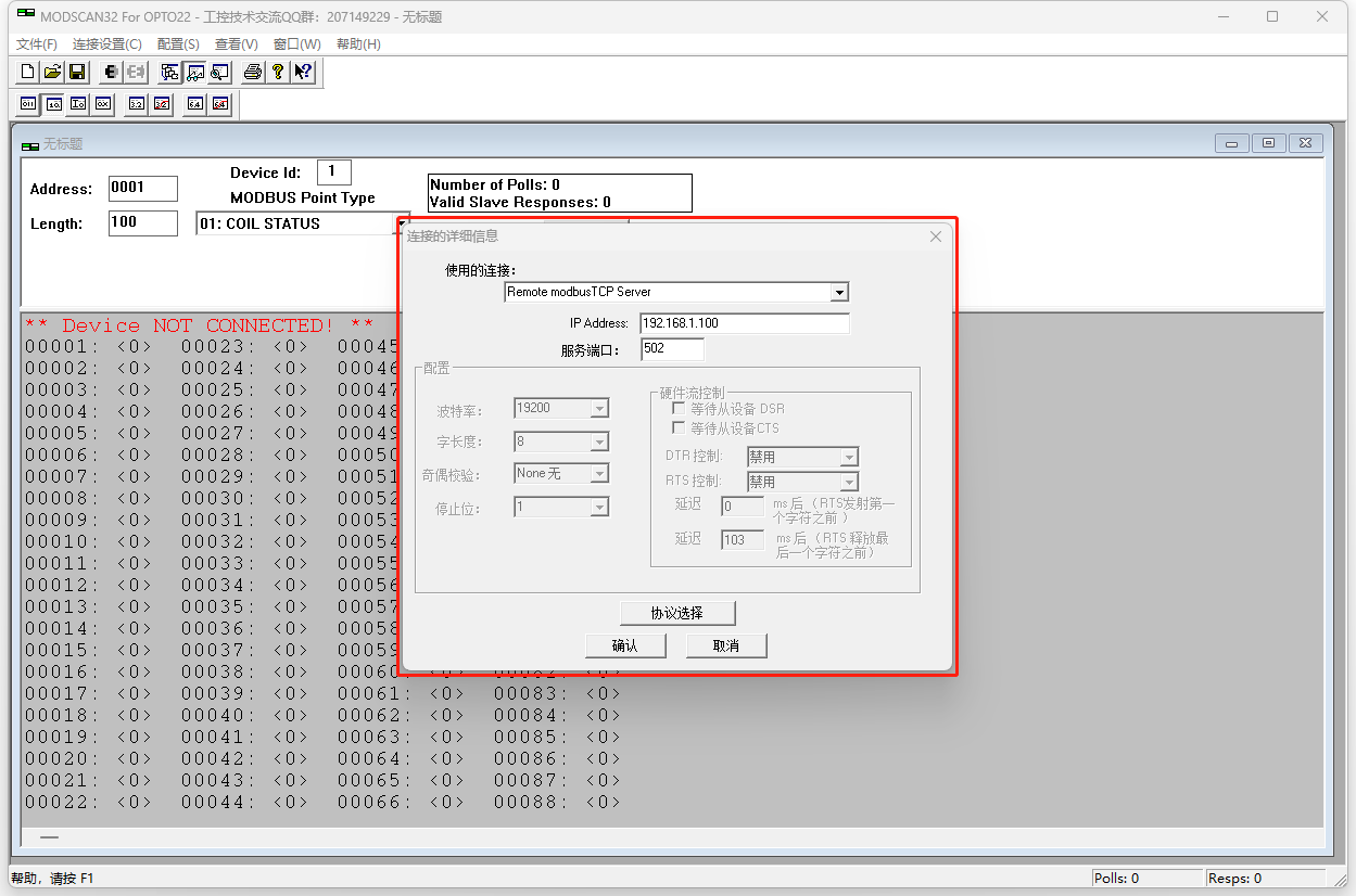
Select from "Used Connection":
Remote modbusTCP Server
Remote TELNET Server
Direct Connection to COM1
Direct Connection to COM2
...
Direct Connection to COM32
Note: "Direct Connection to COMXX" (XX needs to be changed to the actual port address)
Term Explanation
Remote modbusTCP Server Explanation
Modbus TCP is a variant of the Modbus protocol based on TCP/IP networks, which uses Ethernet connections to communicate with remote devices. Through the Remote Modbus TCP Server function, Modscan32 can connect to remote Modbus TCP slave devices as a Modbus TCP master.
Remote TELNET Server Explanation
The Remote TELNET Server (Remote TELNET Server) is a feature in Modscan32 that allows communication with Modbus slave devices over the network via the Telnet protocol. Telnet is a network protocol that enables remote access to computers or devices over a network connection.
Direct Connection to XX Explanation
Connection is made through serial communication, requiring the setting of relevant parameters such as serial port number, baud rate, data bits, etc.
Connection via Serial Port
Configure the port number, baud rate, data bits, parity bit, and stop bit in the configuration window. Generally, the settings are 9600 baud (9600 Baud), 8 data bits (8 Data bits), no parity (None Parity), and 1 stop bit (1 Stop Bit). Of course, these settings need to be matched according to the actual slave device being communicated with.
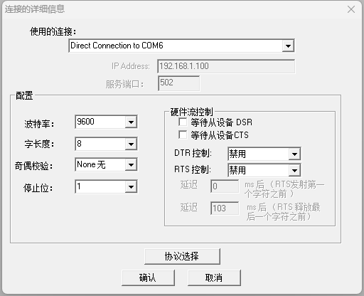
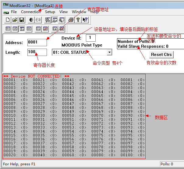
Step 1: Click on "Connection" in the menu bar --- "connect" appears
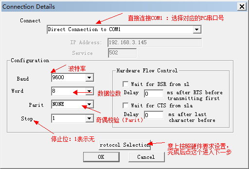
Step 2: Click on "Protocol Selection" to proceed to the next step
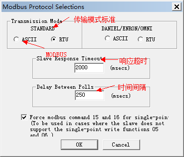
Step 3: Communication Parameter Settings: Perform the following setup operations. Fill in the data as shown in the interface that appears after clicking, as follows
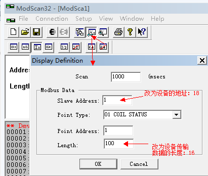
2. Modbus Type Selection:
In "Modbus Point Type", it is the register area to be read:
01: Coil Status (01: COIL STATUS) - (readable and writable)Coil Status refers to the state of the output coil of the Modbus slave, which can be open (1) or closed (0). It is used to control and monitor the switch state of the device.
02: Input Status (02: INPUT STATUS) - (readable only)Input Status refers to the state of the input coil of the Modbus slave, which can be open (1) or closed (0). It is used to monitor the status of external devices or sensors.
03: Holding Register (03: HOLDING REGISTER) - (readable and writable)Holding Registers are Modbus register types used for storing and reading data. They can be used to store and configure parameters, control device operations, etc.
04: Input Register (04: INPUT REGISTER) - (readable only)Input Registers are Modbus register types used for storing read-only data. They can be used to store sensor data, device status, and other information.
Follow the instructions in the hardware product manual to select the appropriate type.
3. PC Display Data Settings:
Click on the menu bar "Configuration(Setup)" -> "Display Options", and a display format window will pop up.
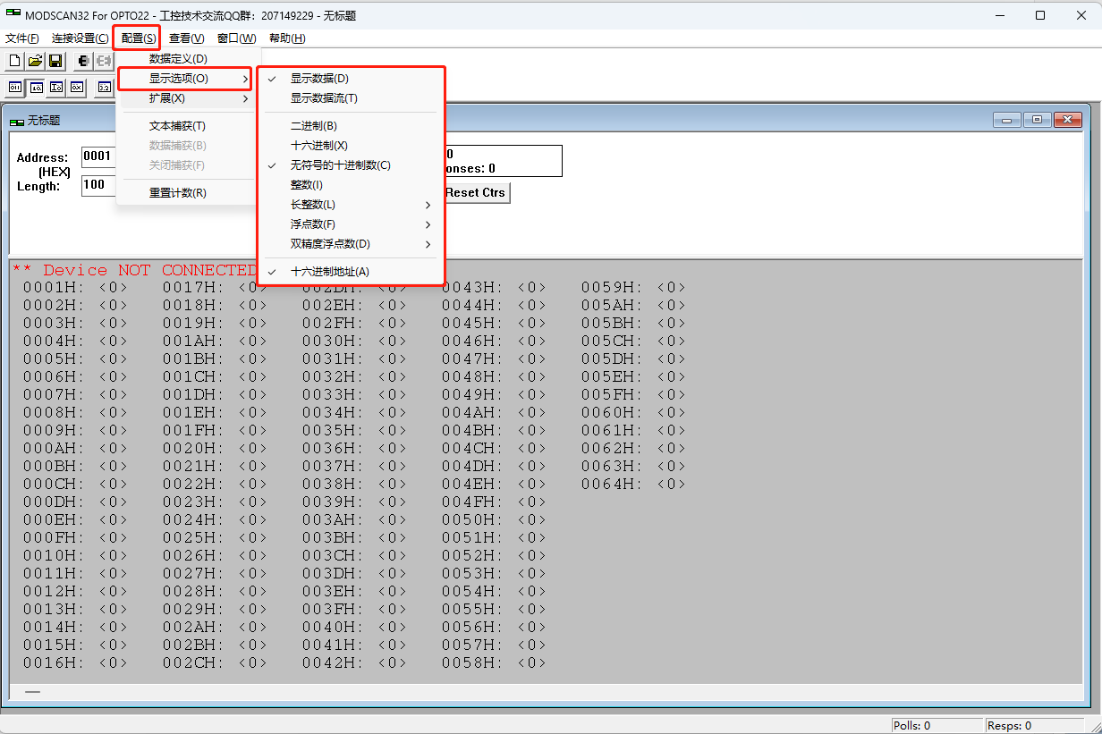

From left to right, they correspond to: binary, octal, hexadecimal
Binary (Binary) -Data format represented in binary form. Range: 0 or 1.
Decimal (Decimal) -Data format represented in decimal form. Range: -32768 to 32767 (16-bit signed number) or 0 to 65535 (16-bit unsigned number); -2147483648 to 2147483647 (32-bit signed number) or 0 to 4294967295 (32-bit unsigned number).
Hexadecimal (Hex) -Data format represented in hexadecimal form. Range: -8000 to 7FFF (16-bit signed number) or 0 to FFFF (16-bit unsigned number); -80000000 to 7FFFFFFF (32-bit signed number) or 0 to FFFFFFFF (32-bit unsigned number).
Long Integer -Data format representing a signed long integer. Range: -2147483648 to 2147483647.
Long (Swapped) -Data format representing a long integer with byte order reversed. Range: -2147483648 to 2147483647.
Floating Point -Data format representing a numerical value with a decimal fraction. Range: Varies depending on the number of floating-point digits.
Float (Swapped) -Data format representing a floating-point number with byte order reversed. Range: Varies depending on the number of floating-point digits.
64-Bit Floats -Data format representing a double-precision floating-point number with higher precision. Range: Varies depending on the number of floating-point digits.
64-Bit Swapped -A 64-bit data format with reversed byte order. Range: Varies depending on the data type.
4. Other function menu items:

From left to right, they correspond to: New, Open, Save, Connect, Disconnect, Data Definition, etc.
After all parameter settings are completed, click OK. If there is data input to the corresponding serial port, the data can be obtained.
Note:
The requirements for Modbus/485 signal access are as follows:
1.The communication parameters for the Server are 9600, 8, 1, and no parity (adjustable, but currently the communication mode parameters for enterprises are consistent).
2.The 485 address of the Server is 1.
3The acquisition points correspond to Modbus RTU addresses starting from 4001, with the data type being RINT.
4.The provided MOdbus RTU Server must be the international standard version protocol, and it should be able to pass the test using the Modscan debugging software.
Address (Address) -The address range of the Modbus slave is 1-255.
Length (Length) -Used to specify the length or quantity of data to be read or written. It can be the number of bytes, bits, or registers, depending on the function code and data type used.
Device ID (Device Id) -The Device ID is a unique identifier used to distinguish different devices in the Modbus network. Each Modbus device has a unique Device ID.
MODBVS Point Type (MODBVS point Type) - MODBVS Point Type refers to the options used in Modscan32 to select different Modbus data types and register types.
Display (Display) -The option in Modscan32 used to select the data display format.
Show Data -The Show Data option is used to display the read Modbus data in Modscan32.
Show Traffic -The Show Traffic option is used to display the transmitted data of Modbus communication in Modscan32.
Window Status Display
Number of Pollsindicates the current number of sent commands.
Valid Slave Responses indicates the number of responses from the target slave.
Red text indicates the current fault status, as detailed in the following fault description.
**Device NOT CONNECTED! ** indicates that no connection is currently established.
**Data Uninitialized** indicates that the current window is not configured.
**MODBUS Message TIME-OUT**: This indicates that the slave device did not respond within the timeout period after the command was sent.
There are many possible reasons why the slave device does not reply, such as:
1. Connection configuration error: The baud rate, Slave ID, and other information of the master device do not match those of the slave device, so the slave will not respond.
2. Line anomaly: There is an anomaly in the communication line between the computer and the slave device, which also prevents normal receipt of a reply.
3. Parsing anomaly in the slave device: This specific issue can be further investigated by referring to the detailed explanation of the Modbus protocol.
**Checksum Error in Response Message**: Response data verification error.
**MODBUS Exception Response from Slave Device**: Address anomaly: Generally, when the accessed slave device does not have the register/coil address to be read, it will return an 02 anomaly code indicating the absence of this address. The software will report this error when it receives this command.


这个可以是CAN协议吗,可以用485码
11
1
不错
1
ceshi
好
1
很好
好
aaaa
好
好
好 飞创好
感谢分享
感谢分享
很好
确实很好
新手村有没有伙伴
看看
很好
Like Like ,很详细 完美!
这个教程太好了!
能用?
能用不
很好很全面
很不错 很全面
解释详尽
好,很全面
好,很全面
好