
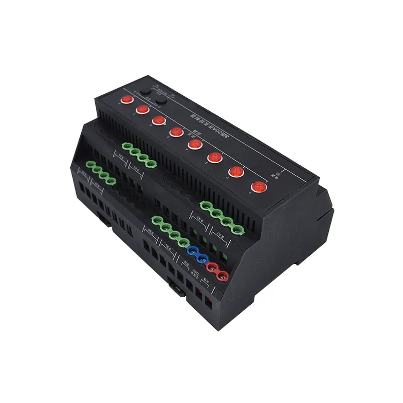
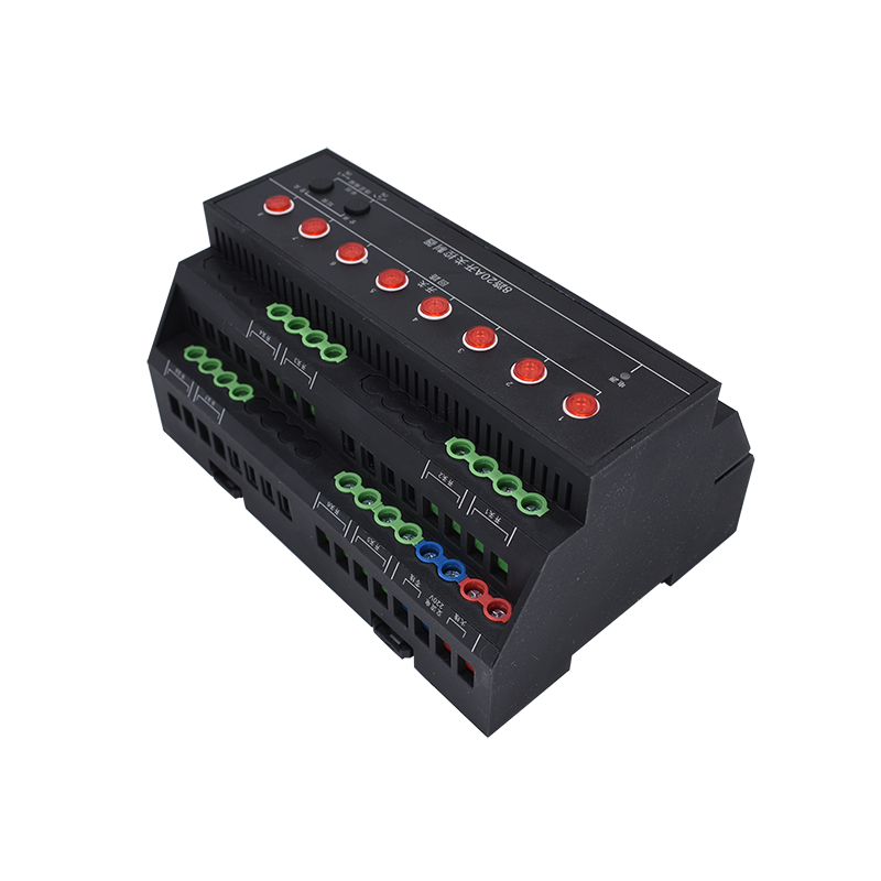
Product Features:
- Corresponding Table for Panel LED Settings
- Communication isolation, Control drive isolation
- The communication method is:RS485
- Support standardsmodbusagreement, supportRTUFormat
- Support manual control mode product functions
- 8Road relay control
- The fire interface supports active input, Passive input, Feedback with dry contacts
- Can be connected to an external dry contact panel, Sensor control, Scenario customization programming
- Supports 6-digit addressing addresses, Can be supported63Networking of individual devices
Main parameters:
| Parameters | explain |
| Contact capacity | 20A/240VAC, 10msAnti surge current165A |
| Durability | 10Ten thousand times |
| Data interface | RS485Mouth |
| Supply voltage | AC 220V |
| Power indicator | 1The road is redLEDinstructions |
| Communication instructions | None |
| Output indication | 8RoadLEDinstructions |
| Temperature range | Industrial grade, -40℃~85℃ |
| Size (mm) | 144*98*72 |
| Weight | 600g |
| Communication format | 1200,n,8,12400,n,8,14800,n,8,19600,n,8,1 (Factory settings)19200,n,8,138400,n,8,1 57600,n,8,1 |
| Software support | Support various configuration software; supportLabviewdWait |
Register description
This control module mainly consists of coil registers, Mainly supports the following instruction codes: 1, 5, 15
| Instruction code | meaning |
| 1 | Read coil register |
| 5 | Write a single coil |
| 15 | Write multiple coil registers |
Coil register address table:
| Register name | Register address | explain |
| Coil1 | 00001 | First relay output |
| Coil2 | 00002 | Second relay output |
| Coil3 | 00003 | Third relay output |
| Coil4 | 00004 | Fourth relay output |
| Coil5 | 00005 | Fifth relay output |
| Coil6 | 00006 | Sixth relay output |
| Coil7 | 00007 | Seventh relay output |
| Coil8 | 00008 | Eighth relay output |
remarks:
①: ModbusThe device instructions support the following:ModbusAddress:
00001To09999It is a discrete output (coil)
10001to19999it is a discrete input (contact)
30001to39999it is an input register (usually an analog input)
40001to49999it is a hold register (reserved)
uses a 5-bit code format, the first character determines the register type, the other 4 characters represent the address. address 1 starts from 0, such as00001corresponding0000.
communication format
this product supports standardmodbusinstruction, detailed instruction format can refer to theMODBUSprotocol.pdf.
this product supportsmodbus RTU format.
local address is a dip switch ground, supports64address devices
localRTUformat code check bits in addition to supportingCRC16value, fixed value AC AC
common instruction set (deviceIDfunction01) :
| format | RTUbase transmission (16query 8-way status) | |
| query return information | 01 01 00 00 00 08 AC AC | |
| control) Open the first channel | 01 01 02 00 00 B9 FC | |
| control the return information | 01 05 00 00 FF 00 AC AC | |
| close the first channel | 01 05 00 00 FF 00 8C 3A | |
| control the return information | 01 05 00 00 00 00 AC AC | |
| open the second channel | 01 05 00 00 00 00 CD CA | |
| close the second channel | 01 05 00 01 FF 00 AC AC | |
| open the third channel | 01 05 00 01 00 00 AC AC | |
| Control the opening of the third channel | 01 05 00 02 FF 00 AC AC | |
| Control the third pass | 01 05 00 02 00 00 AC AC | |
| Control the opening of the fourth route | 01 05 00 03 FF 00 AC AC | |
| Control the fourth pass | 01 05 00 03 00 00 AC AC | |
| Control the opening of the fifth route | 01 05 00 04 FF 00 AC AC | |
| Control the fifth checkpoint | 01 05 00 04 00 00 AC AC | |
| Control the opening of the sixth route | 01 05 00 05 FF 00 AC AC | |
| Control the sixth checkpoint | 01 05 00 05 00 00 AC AC | |
| Control the opening of the seventh route | 01 05 00 06 FF 00 AC AC | |
| Control the seventh checkpoint | 01 05 00 06 00 00 AC AC | |
| Control the opening of the eighth route | 01 05 00 07 FF 00 AC AC | |
| Control the eighth checkpoint | 01 05 00 07 00 00 AC AC |
Detailed explanation of communication format
1: Relay inquiry
Query devices01The 6th relay
01 01 00 00 00 06 A8 07
Or 01 01 00 00 00 06 AC AC
| Fields | meaning | remarks |
| 01 | Equipment address | The device address is0-3F, support64A device |
| 01 | 01Instructions | Query relay status command |
| 00 00 | Starting address | The first relay register address to be queried |
| 00 06 | Query quantity | The number of relays to be queried |
| A8 07 Or AC AC | CRC16 |
Relay return information:
01 01 01 00 51 88
| Fields | meaning | remarks |
| 01 | Equipment address | |
| 01 | 01Instructions | Return instruction: If the query is incorrect, return0x81 |
| 01 | Byte count | Return all bytes of status information. 1+(n-1)/8 |
| 00 | Query status | Return relay status. Bit0:The first relay is in the off stateBit1:The second relay is in the off state. . . . . . . Bit7:The eighth relay is in the off state |
| 51 88 | CRC16 |
2, Single relay control command
Equipment10The third relay is turned on
10 05 00 00 FF 00 8F7B
Or 10 05 00 00 FF 00 AC AC
| Fields | meaning | remarks |
| 10 | Equipment address | The device address is0-3F, support64A device |
| 05 | 01Instructions | Single relay operation instructions |
| 00 00 | Relay address | Value taking0-7, Relay for executing commands (1-8) |
| FF 00 | Perform operations | FF 00To open, 00 00To close |
| 8F 7B Or AC AC | CRC16 |
Relay return information:
10 05 00 00 FF 00 8F 7B
3, Multiple relay control commands
Equipment10The first3, 4, 5, 6The circuit relay is activated, Open, Close, Close the operation
10 0F 00 02 00 04 01 03 C7 97
Or 10 0F 00 02 00 04 01 03 AC AC
| Fields | meaning | remarks |
| 10 | Equipment address | The device address is0-3F, support64A device |
| 0F | 0FInstructions | Multiple relay operation instructions |
| 00 02 | Relay starting address | Value taking00 00-00 07, Start relay for executing commands (1-8) 00 02Starting from the second relay to execute the relay |
| 00 04 | Number of relays executed | |
| 01 | Execution data length | |
| 03 | Execution data | 0th position: Third relay, Open the first position: Fourth relay, Open the second position: 5th relay, Close the third position: 6th relay, Close other positions: Supplement0 |
| C7 97 Or AC AC | CRC16 |
Relay return information:
10 0F 00 02 00 04 F6 89
Note Double:
Oral designCOMAnd with, COM 1For two independent communication portsCOM 2The module can be configured with the upper computer configuration software simultaneously, Configuration screen, Panel communication enables control, 485Double. Oral designCOMResolve the issue of control interference caused by parallel connection of different control terminal serial ports, And with. COM 1Not connectedCOM 2Communication between modules, The mouth must be consistentCOMPower on status.
ID, Baud rate, Baud rate, Restore factory settings
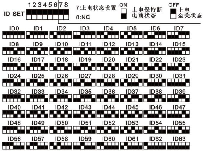
This control module uses a physical dialer for operationIDset up, Power on state mode setting, Baud rate setting, Restore factory settings
IDset up, Power on state mode setting:
Baud rate setting:
- Baud rate display mode: After the control module is powered on, On the module panel1-7of One of them will flash three timesLEDTo indicate the baud rate setting status of the module, Panel.
Set corresponding tableLEDFlashing after being powered on
| LampLEDModule baud rate | Baud rate setting process |
| LED 1 | 1200,n,8,1 |
| LED 2 | 2400,n,8,1 |
| LED 3 | 4800,n,8,1 |
| LED 4 | 9600,n,8,1 |
| LED 5 | 19200,n,8,1 |
| LED 6 | 38400,n,8,1 |
| LED 7 | 57600,n,8,1 |
- Module power failure
(1) Setting up a dialer
(2) IDDial toID8LocationONSetting up a dialer
(3) IDDial to the corresponding settingsID1-ID7Dialer setting correspondence table
Set up a dialer:
| IDModule baud rate | rest |
| ID1-ON, rest-OFF | 1200,n,8,1 |
| ID2-ON, rest-OFF | 2400,n,8,1 |
| ID3-ON, rest-OFF | 4800,n,8,1 |
| ID4-ON, rest-OFF | 9600,n,8,1 |
| ID5-ON, rest-OFF | 19200,n,8,1 |
| ID6-ON, rest-OFF | 38400,n,8,1 |
| ID7-ON, Long press-OFF | 57600,n,8,1 |
(4) Function keys“Module powered on1”
(5) Panel corresponding to baud rate
(6) Flashing onceLED1-7, Setting up a dialer.
(7) IDDial toID8LocationOFFDevice restart, Baud rate setting completed.
(8) Restore factory settings
After the control module is powered on:
1, On the module panel, of One of them will flash three times1-7To indicate the baud rate status of the moduleLEDPanel, Set corresponding table.
Flashing after being powered onLEDLamp
| Module baud rateLEDRestore factory settings process | Module power failure |
| LED 1 | 1200,n,8,1 |
| LED 2 | 2400,n,8,1 |
| LED 3 | 4800,n,8,1 |
| LED 4 | 9600,n,8,1 |
| LED 5 | 19200,n,8,1 |
| LED 6 | 38400,n,8,1 |
| LED 7 | 57600,n,8,1 |
2, Factory reset process
(1) Module power failure
(2) IDSetting up a dialerID8Dial toONLocation
(3) IDSet the 4 dials of the dialer toON, Others - dialOFF
Dialer setting correspondence table:
| IDSet up a dialer |
| ID4-ON, rest-OFF |
(4) Long press“Function keys1”
(5) Module powered on
(6) LED 4The light is flashing, Flashing once.
(7) IDSetting up a dialerID8Dial toOFFLocation, Device restart.
(8) Factory reset completed
Product Purchase: https://item.taobao.com/item.htm?ft=t&id=844942876537


Leave a Reply