

The message formats of Modbus TCP and Modbus UDP are the same, and the difference between them is actually the difference between TCP and UDP. Therefore, the following analysis focuses on the protocol of Modbus TCP. The difference between Modbus TCP and Modbus Rtu (Modbus ASCII) is shown in the following figure:
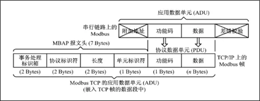
As can be seen from the above figure, ModbusTCPinModbusOn the basis of serial communication, Removed verification (Due toTCPIt already comes with a checksum) And device address (ModbusTCPWeakened the device address, usingIPAddress to replace) , plusMBAPMessage header(accounted for)7 bytes) , Below, we will focus onMBAPProvide analysis and explanation:
| domain | Length | Instructions | client | Server |
|---|---|---|---|---|
| transaction ID | 2byte | ModbusIdentification of request/response transaction processing | Client startup | Copy response |
| Protocol Identifier | 2byte | 0=Modbusagreement | Client startup | Copy response |
| Length | 2byte | Total number of bytes after length | Client startup | Server startup |
| Unit identifier | 1byte | Slave identification of serial links or other buses | Client startup | Copy response |
Below is an analysis of specific messages, ModbusThe message format of the protocol on the Ethernet link is as follows:
| transaction ID | Protocol Identifier | Length | Unit identifier | function code | data |
|---|---|---|---|---|---|
| 2 bytes | 2 bytes | 2 bytes | 1 byte | 1 byte | N bytes |
After establishing the theoretical foundation mentioned above, Below is a detailed analysis of each function code:
Read output coil
The format for sending messages is as follows:

Meaning of sending message: Read the output coil of server No.1 slave station, The starting address is0x13=19, The corresponding address is00020, The number of coils is0x1B=27, Read the output coil of the No.1 slave station, Address from00020-00046, in total27The state value of a coil.
It's worth noting here, The starting address in the protocol refers to the index, The following address refers to the specific address, For any storage area, All indexes start from 0, But the corresponding specific address, Related to storage area, For example, output coil, 0correspond to00001; Input coil, 0correspond to10001; input register, 0correspond to30001; holding register, 0correspond to40001.
The format of the returned message is as follows:

Return message meaning: Return to the output coil of server 1 slave station00020-00046, in total27The state value of a coil, Return 4 bytes, respectivelyCD 6B B2 05.
CD=1100 1101 correspond to 00020-00027
6B=0110 1011 correspond to 00028-00035
B2=1011 0010 correspond to 00036-00043
05=0000 0101 correspond to 00044-00046
Read input coil
The format for sending messages is as follows:

Meaning of sending message: Read the input coil of server No.1 slave station, The starting address is0xC4=196, The corresponding address is10197, The number of coils is0x1D=29, Read the input coil of station 1, Address from10197-10225, in total29The state value of a coil.
The format of the returned message is as follows:

Return message meaning: Return to the input coil of server 1 slave station10197-10225, in total29The state value of a coil, Return 4 bytes, respectivelyCD 6B B2 05.
CD=1100 1101 correspond to 10197-10204
6B=0110 1011 correspond to 10205-10212
B2=1011 0010 correspond to 10213-10220
05=0000 0101 correspond to 10221-10225
Read and hold register
The format for sending messages is as follows:

Meaning of sending message: Read the slave station holding register of server 1, The starting address is0x6B=107, The corresponding address is40108, The number of registers is0x02=2, Read the 1st slave station hold register, Address from40108-40109, The values of two registers in total.
The format of the returned message is as follows:

Return message meaning: Return to server 1 and keep the register from the slave station40108-40109, The values of two registers in total, Return 4 bytes, respectively02 2B 01 06, 40108The corresponding numerical value is0x022B, 40109The corresponding numerical value is0x0106.
Read input register
The format for sending messages is as follows:

Meaning of sending message: Read the input register of server No.1 slave station, The starting address is0x6B=107, The corresponding address is30108, The number of registers is0x02=2, Read the 1st slave station hold register, Address from30108-30109, The values of two registers in total.
The format of the returned message is as follows:

Return message meaning: Return to the input register of server 1 slave station30108-30109, The values of two registers in total, Return 4 bytes, respectively02 2B 01 06, 30108The corresponding numerical value is0x022B, 30109The corresponding numerical value is0x0106.
Pre set single coil
The format for sending messages is as follows:

Meaning of sending message: Pre set the value of a single coil for server No.1 slave station, The coil address is0x00AC=172, The corresponding address is00173, Disconnecting flag0xFF00Indicate the position, 0x000Indicates reset, Set the output coil of the No.1 slave station00173.
The format of the returned message is as follows:

Return message meaning: Pre set single output coil original message return.
Pre set single register
The format for sending messages is as follows:

Meaning of sending message: Pre set the value of a single holding register for server 1 slave station, The register address is0x0087=135, The corresponding address is40136, Write value as0x039E, Pre set the 1st slave station holding register40136value0x039E.
The format of the returned message is as follows:

Return message meaning: Pre set order maintains register and returns original message.
Pre set multiple coils
The format for sending messages is as follows:

Meaning of sending message: Pre set the values of multiple coils for server 1 slave station, The coil address is0x0013=19, The corresponding address is00020, The number of coils is0x0A=10, Write value as0xCD00, Pre set No.1 slave coil00020-00027=0xCD=1100 1101, 00028-00029=0x00=0000 0000.
The format of the returned message is as follows:

Return message meaning: The preset multi output coil return message is returned after removing the number of bytes and specific bytes from the original message.
Preset Multiple Registers
The format for sending messages is as follows:

Meaning of sending message: Pre set the values of multiple registers for server 1 slave station, The register address is0x0087=135, The starting address is40136, The number of registers is0x02=2, The ending address is40137, Write value as0xCD00and0x0A10, Pre set the 1st slave station register40136=0x0105, 40137=0x0A10.
The format of the returned message is as follows:

Return message meaning: The preset multi hold register returns a message after removing the number of bytes and specific bytes from the original message.


Leave a Reply