

What is Modbus RTU protocol?
Slave address 0x01, hold register start address 0x0032, read 2 hold registers
It has been widely accepted and widely used Building Management System The construction (BMS) Industrial Automation Systems (IAS) . Its usability, Reliability and its open-source nature, And it can be used for free on any device or application.
This agreement is made byModicon®Yu1979Annual Development and Release, Used for its programmable logic controller. It is built using master/slave architecture, And support the use ofRS232 / RS485 / RS422Serial devices for protocols. ModbusUsually used in situations where multiple instruments and control devices transmit signals to a central controller or system for data collection and analysis. Industrial automation, supervisory control, and data collection (SCADA) The system usually adoptsModbusagreement.
Modbus RTUWhat does it represent?
Modbus RTU (Remote terminal unit) It's primitiveModbusOne of the two transmission modes defined in the specification. These two modes areModbus RTUandASCII, They are all designed to supportRS232, RS485andRS422Serial devices for protocols. Modbus RTUOne notable feature of it is its use of binary encoding and powerfulCRCError checking. Modbus RTUisModbusImplementation of the protocol, Most commonly used in industrial applications and automated production facilities.
Modbus RTUHow it works?
ModbusA protocol is essentially a system that processes requests and responses from electronic devices. Master/slave architecture used in conjunction with master device requests, These requests are responded to by the slave devices.
What isModbus RTUmain site?
Modbus RTUThe master station is a central device that requests information from connected slave station devices. The central controller in automated production systems can play a roleModbus RTUThe role of the main station. ModbusImplement a main server. The master device obtains information from the slave devices, It can also be written into the registers of the slave device.
What isModbus RTUslave?
Modbus RTUA slave is a device that responds to requests from the master device. It cannot initiate information transmission, And remain in hold mode until responding to requests from the main server.
ModbusThe core of the protocol is called a component Protocol Data Unit (PDU). PDUComposed of functional code and data, Regardless of the type usedModbustransmission mode, Can be consistently constructed. Function code specifies the data requested by the main station.
inModbus RTUIn transmission mode, Additional information package inPDUCreate complete application data units around (ADU) . Before the signal flow and functional code, inModbus RTUUnder the mode, Send 1 byte fromIDTo identify the slave devices that should fulfill the request. Attach toPDUIt is 2 bytesCRC, Ensure sending and receiving the correct number of bytes.
ModbusThe device supports four data tables, Used to facilitate communication between devices. They are discrete inputs, Discrete output (coil) , Input register and hold register. Register performs different functions, Not every device is included. In some cases, Only keep registers forI / OFunction.
| field | visit | Size | Description |
|---|---|---|---|
| Discrete Input | read-only | 1bit | Used as input |
| Coil output | Read/Write | 1bit | Used for controlling discretization |
| input register | read-only | 16bit | Used for input |
| Holding registers | Read/Write | 16bit | Used for various things, Including input, Output, Configure data, etc. |
Function code indicates how the master device interacts with the slave deviceIDInteracting with specified slave devices. According to the function code sent, The master device can read a register from the slave device, Or write them in.
When the slave station receives a packet containing an error in the request, They will return error codes. For requests such as illegal functions, Specify illegal register addresses that cannot be accessed by the slave station, as well as messages indicating that the slave device is busy or has malfunctioned, Return error code.
Modbus RTURequire you to know or define the baud rate when initiating communication, Character format (8Bit without parity check, etc) And from the stationIDWaiting for parameters. Any mismatch of these parameters will cause your communication attempt to fail.
Let's explain in detail belowModbus RTUData message:
frame structure
frame structure = address + function + data + Verification
address: Occupy one byte, scope0-255, The effective range is1-247, Other special purposes, For example255It's a broadcast address (a broadcast address is a response to all addresses), Normally, it is necessary for the addresses of two devices to be the same in order to perform queries and replies).
function code: Occupy one byte, The significance of function codes is, Do you know what this command is for, For example, you can query the data of the slave machine, You can also modify the data, So different function codes correspond to different functions.
data: According to different function codes, There are different structures, This will be explained in subsequent examples.
Verification: To ensure that the data is not incorrect, Add this and then calculate the previous data to see if they are consistent, If consistent, This indicates that the data in this frame is correct, I'll reply again; If it's different, This indicates that there was an issue with the transmission of your data, The data is incorrect, So I abandoned it.
Below is the function code03and06Explain in detail:
function code0x03(Read)
Host sends: 01 03 00 00 00 01 84 0A
Reply from the machine: 01 03 02 19 98 B2 7E
So what does this set of data mean?
From the structural diagram above, It can be seen that, The data sent by the host is roughly address+function code+data+Verification;
So the analysis is as follows:
Send data parsing
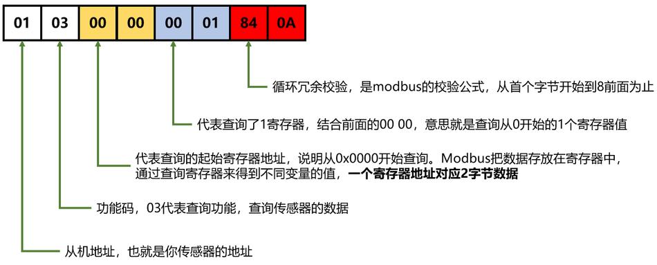
01 - address,That's the address of your sensor
03 - function code,03Representative query function,Query sensor data
00 00 - Representing the starting register address of the query.Explanation from 0x0000Start Query。Here we need to clarify the following:,ModbusStore data in registers,Retrieve the values of different variables by querying registers,One register address corresponds to 2-byte data
00 01 - Representative queried a register.Combining with the previous 00 00,The meaning is to query 1 register value starting from 0
84 0A - Cyclic redundancy check,ismodbusThe verification formula,Starting from the first byte until before 84;
Reply to data analysis
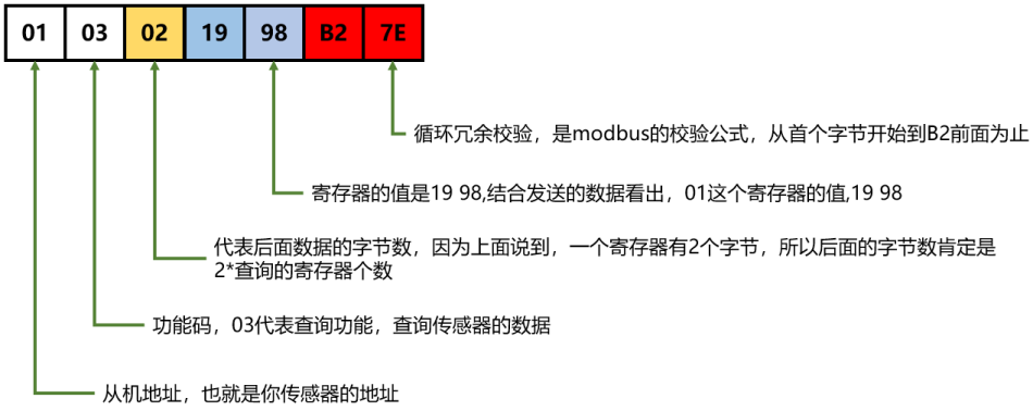
01 - address,That's the address of your sensor
03 - Function code,03Representative query function,Query sensor data。What should be noted here is what the function code sent to the slave is,You need to reply with the same function code from the machine,If they are different, it means there is an error in this frame of data
02 - The number of bytes representing the subsequent data,Because it was mentioned earlier,A register has 2 bytes,So the number of bytes behind it must be 2*Number of registers queried;
19 98 - The value of the register is 19 98,Based on the data sent, it can be seen that,01The value of this register is 19 98
B2 7E - Cyclic redundancy check
Basic Process:
send: The address of the slave+the function code for what I want+the address of the register I want to check+the number of register addresses I want to check+the checksum
Reply: The address of the slave+the function code sent by the host+the number of bytes of data to be sent to the host+data+checksum
function code0x06(Write)
What if I want to modify the data of the slave? So does this agreement exist? The answer isYes!
Host sends: 01 06 00 00 00 01 48 0A
Reply from the machine: 01 06 00 00 00 01 48 0A
Send data parsing
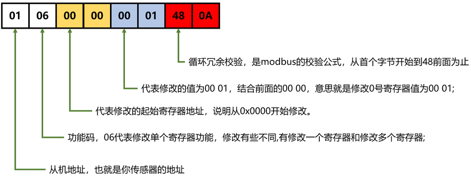
01-The slave address that the host wants to query
06-function code,06Representing the modification of a single register function,The modifications are somewhat different,Modifying one register and modifying multiple registers;
00 00-Representing the modified starting register address.Explanation from 0x0000Start.
00 01-The modified value represents 00 01.Combining with the previous 00 00,The meaning is to modify the value of register 0 to 00 01;
48 0A-Cyclic redundancy check,ismodbusThe verification formula,Starting from the first byte until before 48;
Reply to data analysis
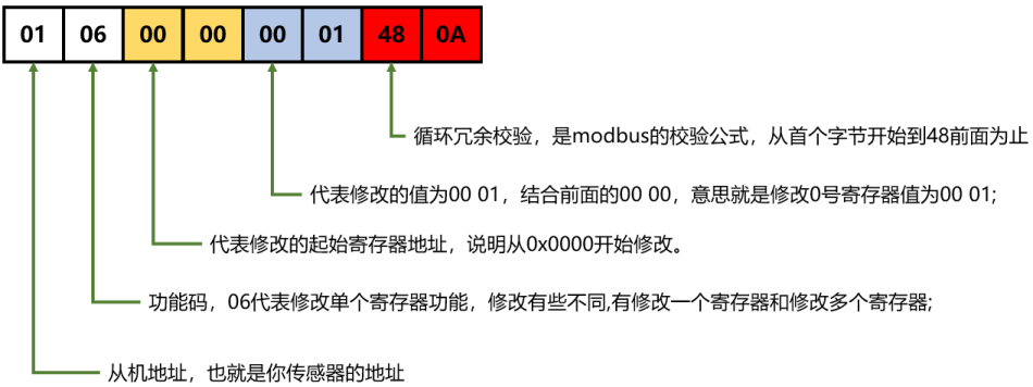
01-Return the host's own address from the slave,This indicates that this is the slave machine checked by the host
06-function code,Representing the modification of a single register function,What function code does the host send,What function code must be returned from the machine;
00 00-Representing the modified starting register address.Explanation is 0x0000.
00 01-The modified value represents 00 01.Combining with the previous 00 00,The meaning is to modify the value of register 0 to 00 01;
48 0A-Cyclic redundancy check,ismodbusThe verification formula,Starting from the first byte until before 48;
Detailed explanation of commonly used function codes
Common Function Code Table
| function code | Name | data type | effect |
|---|---|---|---|
| 0x01 | Read coil register | bit | Obtain the current state of a set of logic coils (ON/OFF) |
| 0x02 | Read discrete input registers | bit | Obtain the current state of a set of switch inputs (ON/OFF) |
| 0x03 | Read and hold register | integer, floating-point type, Character type | Retrieve the current binary value from one or more hold registers |
| 0x04 | Read input register | integer, floating-point type | Retrieve the current binary value from one or more input registers |
| 0x05 | Write a single coil register | bit | Forcefully set the on/off state of a logic coil |
| 0x06 | Write a single hold register | integer, floating-point type, Character type | Load specific binary values into a hold register |
| 0x0F | Write multiple coil registers | bit | Forcing the on/off of a series of continuous logic coils |
| 0x10 | Write multiple hold registers | integer, floating-point type, Character type | Load specific binary values into a continuous string of hold registers |
01H-Read coil status
1) Description: Read the slave coil register, bit manipulation, Read single or multiple items;
2) send command:
Assuming the slave address bit0x01, Register start address0x0023, Register End Boycott0x0038, Total reads21A coil. The protocol diagram is as follows:

3) Response:
Return the coil status corresponding to each bit of the data, 1-ON, 0-OFF,As shown in the figure below;

In the table abovedata1express0x0023-0x002aThe state of the coil, data1The lowest bit represents the coil state of the lowest address, It can be understood as the small end mode;
data2Indicate address0x002b-0x0033The state of the coil, As shown in the table below:

data3Indicate address0x0034-0x0038The state of the coil, Not enough for 8 digits, The byte high-order padding is0, As shown in the table below:

02H-Read discrete input states
1): Read discrete input registers, bit manipulation, Read single or multiple items, Protocol like function code0X01agreement, This province;
03H-Read and hold register
1)Description: Read and hold register, Byte instruction operation, Read single or multiple items;
2)send command:
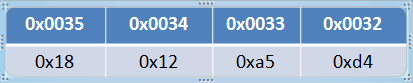
slave address0x01, Maintain the starting address of the register0x0032, Read 2 hold registers

3)Response:

Data storage order
04H-Read input register
1)Description: Read input register, Byte instruction operation, Read single or multiple items;
2)send command: Same03H;
3)Response: Same03H;
05H-Write a single coil
1)Description: Write a single coil, bit manipulation, Only one can be writtenWrite it0xff00Set the coil status toONWrite it0x0000Set the coil status toOFF
2)send command:
Settings0x0032The coil isON;

3)Response:
Send instructions together;
06H-Write a single hold register
1)Description: Write a single hold register, Byte instruction operation, Only one can be written;
2)send command:
Write0x0032Keep the register as0x1232;

3)Response: Send instructions together;
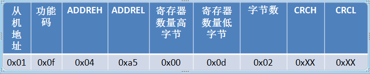
0F-Write multiple coils
1)Description: Write multiple coil registers. If a value in the data area is“1”The status of the requested corresponding coil isON, If a certain value is“0”, The state isOFF.
2)send command:
The coil address is0x04a5Write it12A coil,

In the above pictureDATA1for0x0c, express:

DATA2for0x02, Not enough for 8 digits, Byte high-order padding0:

3)Response:
10H-Write multiple hold registers
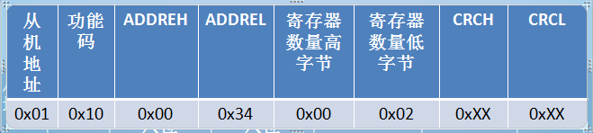
1)Description: Write multiple hold registers, Byte instruction operation, Can write multiple;
2)send command:
Keep the starting address of the register as0x0034,Write 2 registers and 4 bytes of data;

3)Response:


Leave a Reply