
1. Product Introduction
1.1. Product Introduction
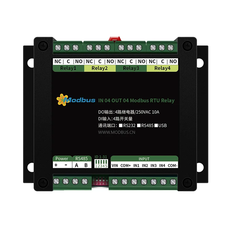
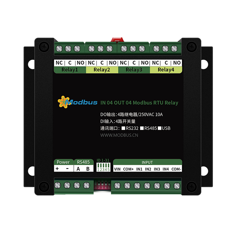
The MODBUS-0404 series products are relay devices that use the standard Modbus RTU protocol and support RS485/232 or network communication. Supporting wide voltage power supply and multi-channel input/output control, it can be widely used in various application scenarios such as industrial production, agriculture, smart cities, office buildings, etc.
1.2. Working mode description
Users can modify the working mode of the configuration module in the upper computer software. Please note that the working modes supported by each model of equipment are.
1.2.1. Normal mode
After giving a command to open or close the relay, the relay will take corresponding actions and complete the opening or closing according to the command.
1.2.2. Flash on/off function
Flash off: When the relay is in the closed state, operate the relay to disconnect for a period of time (set parameter * 0.1s) and then it will automatically close;
Flashing: When the relay is in the disconnected state, operate the relay to close for a period of time (set parameter * 0.1s) and then it will automatically disconnect;
Note: The flashing on/off function is implemented by sending instructions and cannot be set using the upper computer software for mode settings. Support separate control of delay actions for a channel.
1.2.5. Local Interlock Mode
The module itself has a board module with optocoupler input and relay output. In this mode, every time the optocoupler inputs a signal, the corresponding relay will engage, and other optocouplers without input signals will disconnect their corresponding relays. Namely:
The optocoupler input signal takes effect ➞ the corresponding relay is engaged and other relays are disconnected;
Optocoupler input signal cancelled ➞ Relay does not operate.
This mode also has the delay problem of non lock mode, but the delay time will not exceed 0.05 seconds.
This mode is mainly used for external signal triggering to control the start and stop of different devices. For example, if a multi-channel optocoupler is connected to an external button and the corresponding relay is connected to an external electrical device, pressing one button will switch the corresponding device to the starting state, and other devices will stop running.
1.2.6. Dual machine non lock linkage mode
This mode requires two devices with the same address and mode to complete. After the two devices are connected through direct 485 or cross 232, the optocoupler status of module 1 will directly control the status of the corresponding relay of module 2. Namely:
The input signal of optocoupler 1 in module 1 is effective, and the relay 1 in module 2 is engaged;
The input signal of optocoupler 1 in module 1 disappears, and the relay 1 in module 2 is disconnected
The corresponding delay time of the relay in this mode is longer than the previous modes, but it will not exceed 0.1 seconds (9600 baud rate)
If a 485 bus is used in this mode, multiple devices can be connected in parallel, with each device matching its address, allowing for remote transmission of switch values. For example, if there are multiple low-speed switch signals on site that need to be transmitted to a control room 500 meters away to control alarm lights or electric bells, then only a few modules need to be arranged in the factory and connected to the corresponding modules in the room through two twisted pair shielded wires to complete the task. Similarly, the button signals for operating the computer room can also be directly transmitted to
Located on the relay of the computer room module.
1.2.7. Dual machine self-locking linkage mode
This mode requires two devices with the same address and mode to complete. After the two devices are connected through direct 485 or cross 232, the optocoupler status of module 1 will take effect and flip the corresponding relay status of control module 2, that is:
Module 1's input signal from optocoupler 1 takes effect ➞ Module 2's relay 1 flips;
The input signal of optocoupler 1 in module 1 disappears, and the relay 1 in module 2 does not operate
The application of this mode is similar to the "dual machine non lock linkage" mode, but it is more suitable for remote control of device start and stop, as long as
Installing a button on the operating end can achieve the action of pressing once to start and once to stop.
Product working mode diagram
2. Specification parameters
Product specifications and parameters
| parameter | Explanation |
| Working Voltage | 9-28V DC (supports anti reverse connection) |
| Equipment power consumption (W) | 12V power supply: not open:<0.5; Fully open:<324V power supply: not open:<0.5; Fully open:<3 |
| power indicator | with 1 red LED indicator |
| communication interface | isolated RS485 |
| communication protocol | standard Modbus RTU |
| baud rate | 1200240048009600 (default), 1920038400 can be modified through software |
| Default communication format | 9600, n, 8, 1 |
| Device address | 0-255, 5-digit address dip switch can set 1-31 address codes, and those greater than 31 can be set through software; |
| IO interface | 4-channel DI (optocoupler isolation); 4-channel DO (normally open and normally closed, output terminal contact isolation) |
| Output contact capacity | 10A/30VDC or 10A/250VAC |
| Durability | 100000 times |
| Output indication | Equipped with 4-channel red LED indicator lights |
| Equipment size | 115 * 90 * 40mm |
| Weight | Approximately 330g |
| Operating temperature | Industrial grade, -40 ° C~70 ° C |
| Operating humidity | 5~85% RH |
| Product function | Flash on/off, computer upper computer control, local non lock linkage, local self-locking linkage, dual machine non lock linkage, dual machine self-locking linkage, local interlock mode |
| Software support | Work mode change; Relay independent control; Query of switch status; Relay overall control; Debugging information query; Control software; Support various configuration software; Support Labview, etc |
| Card rail installation | Standard DIN35mm rail installation |
3. Product dimensions
Product dimension diagram
4. Communication protocol and data format
4.1. Upper computer software download
"Langhand IO Controller Configuration Tool"
Software screenshot
4.2. Device communication configuration
4.2.1. Introduction to DIP switch function
Device address (slave address)=DIP address+software address
For example, if the DIP address is set to 11 and the software address is set to 110, then the device address is 121. Change address
needs to be powered off and restarted before it can take effect.
5-digit dip switch
The device is equipped with a dip switch for users to quickly modify the device address. When all five dialing codes are dialed to the top, it is the address "31"; When all five dialing codes are dialed to the bottom, it is the address "0";
When all five dialing codes are dialed to the top, it is the address "31";
(2) When all five dialing codes are dialed to the bottom, it is the address' 0 ';
(3) The leftmost 1 is the binary lowest bit;
(4) Dialing Address Table:
Dialing Switch Address
4.2.2. Software Address Setting and Reading
Click "Read" or "Set" after the software address below the upper computer software to read or set the software address of the device.
Software Address Setting
Device Address
4.2.3. Setting and Reading of Baud Rate
Click on "Read" and "Set" in the baud rate setting bar of the upper computer software to read and set the baud rate
and address respectively. After operation, the device needs to be restarted and the computer serial port settings need to be modified.
Baud rate setting
4.3. Communication protocol description
This product supports standard Modbus instructions. For detailed instruction generation and parsing methods, please refer to the register table in
in this article and refer to the "Modbus Protocol Chinese Version". This product supports Modbus RTU format.
4.3.1. Modbus Register Description
Coil Register Address Table:
| Register Name | PLC Register Address | Description | |
| Coil Control | |||
| Coil 1 | Write Coil 1 Instruction Code | 00001 | First Relay Output |
| Coil 2 | 00002 | Second Relay Output | |
| Coil 3 | 00003 | Third Relay Output | |
| Coil 4 | 00004 | Fourth Relay Output | |
| Discrete Input | |||
| Input 1 | Switch No.2 Instruction | 10001 | 1st Input |
| Input 2 | 10002 | 2nd Input | |
| Input 3 | 10003 | 3rd Input | |
| Input 4 | 10004 | 4th Input |
Configuration Parameters
| Register Name | Modbus Register Address | PLC Register Address | Description | |
| Communication baud rate | Holding register | 03E8H | 41001 | Refer to the table below for the corresponding baud rate values. The default value is 0 and supports 0-5. This register also determines the communication baud rate for RS232 and RS485 |
| Backup | 03E9H | 41002 | Backup, and users cannot write any values | |
| Offset address | 03EAH | 41003 | Device Address=Offset Address+DIP Switch Address | |
| Operating Mode | 03EBH | 41004 | Users can use, store user data |
Remarks:
(1) Modbus device instructions support the following Modbus addresses:
00001 to 09999 are discrete outputs (coils)
10001 to 19999 are discrete inputs (contacts)
30001 to 39999 are input registers (usually analog inputs)
40001 to 49999 are hold registers (usually storing device configuration information)
Adopting a 5-bit code format, the One character determines the register type, and the remaining four characters represent the address. Address 1 starts from 0, such as 00001 corresponding to 0000.
(2) Baud Rate Value Correspondence Table
| Value | Baud rate |
| 0 | 9600 |
| 1 | 2400 |
| 2 | 4800 |
| 3 | 9600 |
| 4 | 19200 |
| 5 | 38400 |
(3) Relay status, query relay status and control through address 00001;
Switch status, query switch status through address 10002.
The register address follows the PLC naming convention, where the real address is obtained by removing the highest bit and then subtracting one.
4.3.2. Instruction List
| Instruction Name | RTU Format (hexadecimal) |
| Query Four Channel Status | FE 01 00 00 04 29 C6 |
| Query Instruction Return Information | FE 01 00 61 9C |
| Control the first channel to open | FE 05 00 00 FF 00 98 35 |
| Control the return information | FE 05 00 FF 00 98 35 |
| Control the first channel to close | FE 05 00 00 00 D9 C5 |
| Control the return information | FE 05 00 00 00 D9 C5 |
| Control the second channel to open | FE 05 00 01 FF 00 C9 F5 |
| Control the second channel to close | FE 05 00 01 00 88 05 |
| Control the opening of the third channel | FE 05 00 02 FF 00 39 F5 |
| Control the closing of the third channel | FE 05 00 00 78 05 |
| Control the opening of the fourth channel | FE 05 00 03 FF 00 68 35 |
| Control the closing of the fourth channel | FE 05 00 00 00 29 C5 |
| Read the first channel optocoupler | FE 02 00 00 01 AD C5 |
| Return information | FE 02 01 00 91 9C |
| Read the 2nd optocoupler | FE 02 00 01 01 FC 05 |
| Read the 3rd optocoupler | FE 02 00 01 0C 05 |
| Read the 4th optocoupler | FE 02 00 03 00 01 5D C5 |
4.3.3. Instruction Explanation
4.3.3.1. Relay Output
Control the 1st relay (taking the 1st channel as an example, refer to this example for other channels)
Send Code: FE 05 00 00 00 FF 00 98 35
| Field | Meaning | Remark |
| FE | Device address | This is the broadcast address |
| 05 | 05 instruction | Single control instruction |
| 00 00 | Address | To control the relay register address |
| FF 00 | Instruction | The action of closing the relay |
| 98 35 | CRC 16 | CRC 16 checksum for the first 6 bytes of data |
Relay module return information:
Return code: FE 05 00 00 FF 00 98 35
| field | meaning | Remark |
| FE | Device address | This is the broadcast address |
| 05 | 05 instruction | Single control instruction |
| 00 00 | Address | To control relay register address |
| FF 00 | Instruction | Relay closing action |
| 98 35 | CRC 16 | CRC 16 checksum of the first 6 bytes of data |
4.3.3.2. Relay status
Relay query
Send instruction code: FE 01 00 00 04 29 C6
| Field | Meaning | Remarks |
| FE | Equipment Address | Here is the broadcast address |
| 01 | 01 Instruction | Query Relay Status Instruction |
| 00 00 | Starting Address | First Relay Register Address to be queried |
| 00 04 | Query Quantity | Number of Relays to be queried |
| 29 C6 | CRC 16 | CRC 16 checksum of the first 6 bytes of data |
Relay return information:
Return code: FE 01 00 61 9C
| Field | Meaning | Remarks |
| FE | Device address | |
| 01 | 01 instruction | Return instruction. If the query is incorrect, return 0x81 |
| 01 | byte count | Return all bytes of status information. 1+(n-1)/8 |
| 00 | Query status | The return value is hexadecimal, converted to binary data, with 0 indicating off and 1 indicating on. For example, if the return field of a 4-channel relay is 08 and converted to binary 1000, then the 1st, 2nd, and 3rd channels will be turned off and the 4th channel will be turned on. |
| 61 9C | CRC 16 | CRC 16 checksum of the first 6 bytes of data |
4.3.3.3. Optocoupler input
query optocoupler
Send instruction code: FE 02 00 00 00 04 6D C6
| Field | Meaning | Remarks |
| FE | Device Address | |
| 02 | 02 Instruction | Query Discrete Input (Optocoupler Input) Status Instruction |
| 00 00 | Starting Address | Register Address of the First Optocoupler to be queried |
| 00 04 | Query Quantity | Optocoupler Status to be queried |
| 6D C6 | CRC 16 | CRC 16 checksum for the first 6 bytes of data |
Optocoupler return information:
Return code: FE 02 01 00 91 9C
| field | meaning | Remark |
| FE | Device address | |
| 02 | 02 instruction | Return instruction. If the query is incorrect, return 0x82 |
| 01 | byte count | Return all bytes of status information. |
| 00 | and the optocoupler status returned by | . Bit0: First optocoupler status Bit1: Second optocoupler status... Bit7: Eighth optocoupler status |
| 919C | CRC 16 | CRC 16 checksum of the first 6 bytes of data |
4.3.3.4. Flash on/off command
Flash off sending code: FE 10 00 03 00 02 04 00 0A 41 6B
Flash development sending code: FE 10 00 03 00 02 04 00 0A A1 6A
| Field | Meaning | Remarks |
| FE | Device address | Hexadecimal, representing decimal 254 broadcast address |
| 10 | 10 Instructions | Write multiple register function codes |
| 00 03 | Relay address | 3+5 (n-1), n represents which channel to control, decimal needs to be converted to hexadecimal |
| 00 02 | Control the number of instructions | 2+5 (n-1), where n represents the number of controlled channels and only supports controlling the delay action of one channel separately |
| 04 | Control the byte length of content | 4+10 (n-1), where n represents the number of channels to be controlled and only supports the delay action of controlling one channel separately |
| 00 04 or 00 02 | Instruction | 00 04 is the flash close command and 00 02 is the flash open command |
| 00 0A | Flash off time | 00 0A is converted from hexadecimal to decimal, which is 10. The interval time is (0.1 seconds * 10) |
| 41 6B or A1 6A | CRC 16 | check digit |
Return code: FE 10 00 03 00 02 A5 C7
| field | meaning | Remark |
| FE | Device address | |
| 10 | 10 Instructions | Return instruction. If the query is incorrect, return 0x82 |
| 00 03 | Device address | Query the address of the device |
| 00 02 | Number of accepted commands | The number of instructions received by the device |
| A5 C7 | CRC 16 | check digit |
Example: 1 second off/off time
Channel 1 Flash Closed FE 10 00 03 00 02 04 00 04 00 0A 41 6B
2-channel flashing closure FE 10 00 08 00 02 04 00 04 00 0A 00 D8
3-channel flash closure FE 10 00 0D 00 02 04 00 04 00 0A C0 E7
4-channel flash closure FE 10 00 12 00 02 04 00 04 00 0A 81 AB
Channel 1 flashes FE 10 00 03 00 02 04 00 02 00 0A A1 6A
2-channel flashing FE 10 00 08 00 02 04 00 02 00 0A E0 D9
3-channel flashing FE 10 00 0D 00 02 04 00 02 00 0A 20 E6
4-channel flashing FE 10 00 12 00 02 04 00 02 00 0A 61 AA
4.3.3.5. Fully open and fully close command
Full development code: FE 0F 00 00 04 01 FF 31 D2
Total disconnection sending code: FE 0F 00 00 04 01 00 71 92
| field | meaning | Remark |
| FE | Device address | |
| 0F | 0F instruction | Return instruction. If the query is incorrect, return 0x82 |
| 00 00 | starting address | |
| 00 04 | Control quantity | Number of relays controlled |
| 01 | byte count | Number of instruction bytes sent |
| FF (or 00) | Fully open (fully closed) command | FF fully open command; 00 full close instruction |
| 31 D2 (or 71 92) | CRC 16 | check digit |
Complete disconnection and full open return code: FE 0F 00 00 04 40 07
| field | meaning | Remark |
| FE | Device address | |
| 0F | 0F instruction | Return instruction. If the query is incorrect, return 0x82 |
| 00 00 | starting address | |
| 00 04 | quantity | Number of relays returning information |
| 40 07 | CRC 16 | check digit |
4.4. Proactively report protocol
This function is a non-standard Modbus protocol and can only be used in dual machine mode. It is suitable for serial port relays to actively report changes in switch values.
| Field | Meaning | Remarks |
| 0x40 0x57 | Header | |
| 0x01 | Device Address | |
| 0x02 | IO Status Low Eight Bits | |
| 0x00 | IO Status High Eight Bits | |
| 0x42+0x01+0x02+0x00 | Check Bit | 0x42+Device Address+IO Status Low Eight Bits+IO Status High Eight Bits |
5.2. Product Terminal Definition
Product Terminal Definition
| Serial Number | Pin | Description |
| 1 | + | Positive pole of power supply |
| 2 | - | Negative pole of power supply |
| 3 | A+ | RS485 A+ |
| 4 | RS485 B - | |
| 5 | VIN | Used for short circuiting VIN and COM+when passive input, please refer to the input wiring diagram |
| 6 | COM+ | Used for short circuiting VIN and COM+when passive input, please refer to the input wiring diagram |
| 7 | IN1 | 1st switch input |
| 8 | IN2 | Second switch input |
| 9 | IN3 | Third switch input |
| 10 | IN4 | Fourth switch input |
| 11 | COM - | Used for passive input, please refer to the input wiring diagram |
| 12 | Normally open | Fourth relay output normally open |
| 13 | Common terminal | Fourth relay output common terminal |
| 14 | Normally closed | Fourth relay output normally closed terminal |
| 15 | Normally Open | The output of the third relay is normally open |
| 16 | Public End | Third relay output common terminal |
| 17 | normally closed | The output of the third relay is normally closed |
| 18 | Normally Open | The second relay output normally starts |
| 19 | Public End | Second relay output common terminal |
| 20 | normally closed | Second relay output normally closed terminal |
| 21 | Normally Open | The first relay output normally starts |
| 22 | Public End | The first relay output common terminal |
| 23 | normally closed | The first relay output is normally closed terminal |
5.3. Product input wiring diagram
5.4. Product output wiring diagram
6. Product maintenance and upkeep
6.1. Equipment usage environment
- The working voltage of the equipment is 9~28V. If the input voltage is too high or too low, it may cause the equipment to malfunction or even malfunction
Damaged.
2. The DI input terminal of the device adopts optocoupler isolation protection, with a carrying voltage of 5~24V.
3. It is strictly prohibited to overload the DO output terminal of the device. Please wire it correctly within the allowed range (see wiring diagram for details).
4. The equipment is allowed to have an air humidity of 5~85% RH and does not have waterproof capability. In condensation or liquid immersion environments, please
Do not use this product.
5. Relays are components with a certain service life. When the theoretical service life is reached, please replace them in a timely manner to avoid occurrence
6.2. Common Problems and Solutions
(1) 232 Communication, Device Control Has No Response, Does Not Act
The device communicates with the upper computer using a 232 direct connection. RX to RX, TX to TX, GND to GND. (2) Relays can only be turned on, not off
Check whether the read address is the actual device address, whether there is a return command in the debugging information column, and whether the return command is correct. If the read address fails, there is no return command or the return command is abnormal, check the communication line and communication converter.
(3) The relay board cannot establish communication and control using the 485 interface after power supply.
1. Whether the 485 line is reversed and whether the voltage is within the specified range;
2. Fill in the device address of 254 on the software and test whether different baud rates can be controlled.
(4) Multiple devices mounted on the 485 bus failed to send relay closing operation at broadcast address 254.
Broadcast address is used to test when there is only one device on the bus. If there are more than one device, please use a dip switch to distinguish the address and control it, or set the address through software (multiple devices are configured with different addresses), otherwise it will cause all devices to respond simultaneously and cannot be executed correctly.
(5) PLC and equipment cannot communicate normally.
1. Whether the PLC communication parameters match the relay equipment;
2. Is the PLC communication protocol standard Modbus RTU;
3. The definition of Siemens 485 bus AB is opposite to that of this device.
(6) How to restore factory settings
For models with dip switches, the dip switch can be used to restore factory settings. The operation steps are as follows: when powered on, all dip switches should be turned on, and bit5 should be used to respond 6 times (one time, one response counts as one time). Then, all dip switches should be turned off, and the upper computer software (baud rate 9600, address 254) can be used for communication
7. After sales service
7.1. After sales service commitment
Our company provides after-sales service for this machine within one year from the date of sale, but does not include damage caused by improper use. If repair or adjustment is needed, please send it back, but the shipping cost will be borne by yourself. When returning, it is necessary to ensure that the packaging is good to avoid damage during transportation. Our company will provide free repair for any damage to the instrument.
7.2. Disclaimers
This document does not grant any intellectual property license, nor does it grant any intellectual property license, express or implied, or by prohibiting speech or other means. Our company assumes no other responsibility except for the responsibility stated in the sales terms and conditions of its products. And our company makes no express or implied warranties regarding the sale and/or use of this product, including warranties of specific suitability for a particular purpose, merchantability, or liability for infringement of any patent, copyright, or other intellectual property rights. Our company may make modifications to product specifications and descriptions at any time without prior notice.
7.3. contact information
Address: 218 Skyway Creative Building, No. 25 Huangxu Road, Tiangongyuan Street, Daxing District, Beijing
Website: www.modbus.cn
Email: cloud@modbus.cn


Leave a Reply