
Modbus-related product recommendation:peidianxiang.taobao.com
Modbus Poll Introduction
Modbus pollis a highly popular Modbus master device simulator that supports Modbus RTU, ASCII, TCP/IP, and other protocol modes. It enables Modbus communication device personnel to test and simulate the use of communication protocols, thereby facilitating better monitoring, testing, and debugging of devices. It also facilitates observation of various message data during Modbus communication, saving a significant amount of time and greatly improving work efficiency.
It supports multiple document interfaces, allowing simultaneous monitoring of multiple slave devices/data fields. Each window simply sets the slave device ID, function, address, size, and polling interval. You can read and write registers and coils from any window. If you want to change a single register, simply double-click the value. Alternatively, you can change multiple register/coil values. It provides multiple data formats, such as floating point, double precision, and long integer (which can be byte-sequence swapped).
Modbus Poll Operating System Requirements
Hardware Requirements
Processor: Recommended 1 GHz or faster
Memory: 1 GB RAM
Hard Disk: 5 MB free hard disk space
Resolution: 1024 x 768 or higher
Operating System: Supports all Windows versions from Windows 7 to Windows 11.
Modbus Poll 7 supports running on Windows XP.
TERMINATION OF USER LICENSE AGREEMENT
Before using Modbus Poll, you should carefully read the following terms and conditions. Unless you have a different license agreement signed by Witte Software, your use of this software constitutes your acceptance of this license agreement and warranty. If you do not accept these terms, you must immediately stop using this software.
Copyright.
Modbus Poll ("Software") is copyrighted 2002-2022 by Witte Software, with all rights reserved.
Evaluation and Registration.
This is not free software. You are hereby authorized to use this software for evaluation purposes free of charge for a period of 30 days.
If you use the software after the 30-day evaluation period, you will need to pay a registration fee.
Failure to register and use the software after the 30-day evaluation period violates U.S. and international copyright laws.
One registered copy of this software may be used by an individual on one or multiple computers for personal use, or installed on a single computer for multiple users, but not simultaneously.
For information on ordering and pricing, please visithttps://www.modbustools.com/order.html
Modbus Poll licenses are perpetual. Once you have purchased a license for a specific version, and as long as you comply with the license agreement, you may use that version permanently without additional fees.
Distribution.
If you do not include your license key, you are hereby granted permission to copy the software; provide an exact copy of the original to anyone; and distribute the software in its unmodified form electronically. You are expressly prohibited from charging for any such copies.
Limited Warranty.
This software is provided "as is," and WITTE Software disclaims all warranties, express or implied, related to this software, including but not limited to any implied warranties of merchantability and fitness for a particular purpose.
Limitation of Damages.
Neither WITTE Software nor any person involved in the creation, production, or delivery of this software shall be liable for any indirect, consequential, or incidental damages arising from the use or inability to use such software, even if WITTE Software has been advised of the possibility of such damages or claims. In any case, regardless of the form of claim, the liability of WITTE SOFTWARE for any damages shall not exceed the price paid for obtaining the license to use the software. The person using the software assumes all risks of the quality and performance of the software.
Modbus Poll Function
Connection
Modbus polls read/write data from devices using:
- Modbus RTU or ASCII over RS232 or RS485 networks. (USB/RS232/485 converter)
- Modbus TCP/IP
- Modbus over TCP/IP. (Modbus RTU/ASCII encapsulated in TCP packets)
- Modbus UDP/IP
- Modbus over UDP/IP. (Modbus RTU/ASCII encapsulated in UDP packets)
Supported Modbus functions
- 01: Read coil
- 02: Read discrete input
- 03: Read hold register
- 04: Read input register
- 05: Write single coil
- 06: Write single register
- 15: Write multiple coils
- 16: Write multiple registers
- 17: Report server ID
- 22: Mask write register
- 23: Read/write register
- 43/14: Read device identification
data records
- Record data to a text file
- Record data directly to Excel
Display format
- Each cell can be formatted individually.
- Signed 16-bit register
- Unsigned 16-bit register
- Hexadecimal
- Binary
- 32-bit signed integer with any word/byte order
- 32-bit unsigned integer with any word/byte order
- 64-bit signed integer with any word/byte order
- 64-bit unsigned integer with any word/byte order
- 32-bit floating-point number with any word/byte order
- 64-bit double-precision floating-point number with any word/byte order
Other functions
- OLE/automation for interfacing with Excel VBA, Python, etc.
- Monitoring data traffic
- Print and print preview
- Font selection
- Conditional color
- Zoom
- Real-time chart
Overview
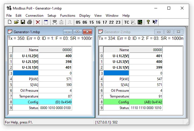
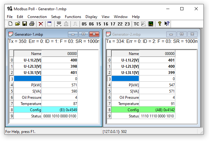
Modbus Poll supports a multi-window interface, allowing simultaneous monitoring of multiple Modbus slaves and data areas. For each window, simply specify the Modbus slave's ID, function code, address, length, and polling time, and you can read and write registers and coils from any window.
Instructions
Press F1to access the help documentation related to the currently selected item.
SHIFT + F1invokes a special "Help Mode", where the cursor changes to a help cursor (arrow + question mark). Users can then select visible objects in the user interface, such as menu items, toolbar buttons, or windows. This will open help on the topic describing the selected item.
Named Cell
You can type any text here to specify a value cell. You can also copy/paste text from an Excel cell.
Value Cell
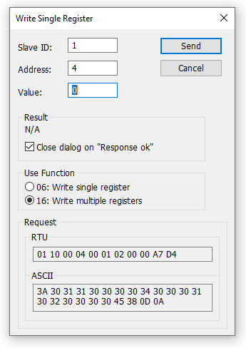
displays the data value of a Modbus register. If you double-click a value cell, a dialog box allows you to write a new value to the slave device. Typing a number in the value cell also displays the dialog box. You can select the Modbus function used to write the value.
The check box "Close dialog on Response ok" is used to automatically close the dialog box when the value is successfully sent. This is convenient when changing a large number of values. This allows you to quickly select a new cell and then type a new value again.
Change Font
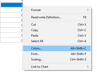
To change the font, you have 2 options
- Select the cell you want to change, and then right-click.
- Select the cell you want to change, and then choose Menu → Display → Font.
Conditional Colors
Conditional colors help you visually display values within a specific range. 3 color options
- Default color: If no conditional color evaluates to true, this color is used.
- Rule 1: If the expression evaluates to true, this color option is used.
- Rule 2: If the expression evaluates to true, this color option is used. Rule 2 takes precedence over Rule 1.
7 comparison operators
- Not used
- Equal to
- Better than...
- Less than
- Greater than or equal to
- Less than or equal to
- And
When the data type is floating-point or 32-bit long, the 'and' operator cannot be used. If 'and' is selected, the condition value is entered in hexadecimal format. If any bit in the cell and the condition value is 1, the calculation result is true.
Color example
If the cell value is between 398 and 402, it is green
Scaling
Scaling helps you convert the original value to a human-readable value. Scaling is only applicable to signed and unsigned 16/32-bit integers.
(X1,Y1) and (X2,Y2)
Line passing through (X1,Y1) and (X2,Y2)
Slope = m = (y2 - y1) / (x2 - x1) Equation of line
Yes = m ⋅ (X - X1) + Y1 Yes = m ⋅ (X - X1) + Yes1 Precise
Number of digits after the decimal point. Enable
to scale values from Modbus server/slave. Scaling is automatically disabled if a display format other than 16/32-bit integer is selected.
Real-time Chart
This chart can plot up to 12 series in real-time, with each series containing up to 100,000 points.
Open a new window
To open another window, you have 3 options:
Connection Dialog
To open the Connection Dialog, you have 2 options:
- Press F3
- Select Connection from the Connection Menu
Contact
There are 5 different connection types:
- Serial:
Modbus over serial line. RS232 or RS485. A USB serial converter can be used. - Modbus TCP/IP:
If you want to communicate with a MODBUS TCP/IP network, select TCP/IP. In this case, the slave ID is the same as the unit ID used in MODBUS TCP/IP.
The port number defaults to 502.
If the connection fails, try pinging the device from the command prompt. If the ping command fails, then Modbus Poll will also fail. - Modbus UDP/IP:
If you want to communicate with a MODBUS UDP/IP network, select UDP/IP. This is the same as Modbus TCP/IP, but uses the connectionless UDP protocol. - Modbus RTU/ASCII over TCP/IP:
This is RTU or ASCII messages sent over a TCP/IP network instead of a serial line. - Modbus RTU/ASCII over UDP/IP:
This is an RTU or ASCII message sent over a UDP/IP network rather than a serial line.
| Connection types 3-5 are not the standard Modbus specified inwww.modbus.org, but they have been added for convenience. |
Depending on your selection, some other settings will be grayed out.
Serial Settings
Use these parameters to set the serial port settings. They are only available when the connection type is "Serial Port". Mode
Use this option to select theRTUOrASCIImode. Default is RTU. Response Timeout
Specify the length of time Modbus Poll should wait for a response from the device before giving up. The default value is 1000 milliseconds. Minimum Delay between Polls
This setting ensures a minimum delay before transmitting the next request, regardless of the scanning rate. The resolution of this setting is approximately 15ms. Better resolution may be achievable on some computers, but not all.
| If this value is set to less than 20 milliseconds, the time interval of 3.5 characters between the response and the new request cannot be guaranteed. This is because the Windows scheduler switches tasks every 10 to 20 milliseconds. If you are polling multiple slaves in a serial RS485 network, you should not set this value to less than 20 milliseconds. This is to ensure the time interval of 3.5 characters. In TCP/IP networks, values less than 20 milliseconds are acceptable. Values less than 20 milliseconds are acceptable for serial connections with only one slave device. |
Remote Server
Remote Server settings are only available when using an Ethernet connection. IP Address
Server IP address. The default is localhost 127.0.0.1Port
Server port number. The default is 502Connection Timeout
Maximum time used to establish a connection. The default is 1000
Advanced Settings
RTS Toggle
RTS Toggle specifies that if bytes are available for transmission, the RTS line will be at high level. After all buffered bytes are sent, the RTS line will be at low level.
If you have a 232/485 converter without an automatic direction switch, you can use it to switch directions.
| If possible, avoid using RTS-controlled RS232/RS485 converters. For non-real-time operating systems such as Windows and Linux, it is difficult to determine the exact time to turn off the transmitter. If it is turned off too early, characters may still be in the FIFO or UART transmit register, and these characters will be lost. Therefore, the slave will not recognize the message. On the other hand, if it is turned off too late, the slave's message will be corrupted, and the master will not recognize the message. |
DSR
DSR specifies whether to monitor the DSR (Data Set Ready) signal for output flow control. If this member is TRUE and the DSR is turned off, output will be paused until the DSR is sent again
CTS specifies whether to monitor the CTS (Clear to Send) signal for output flow control. If this checkbox is enabled and CTS is turned off, output will pause until CTS is sent again. DTR
DTR specifies whether to enable or disable DTR when opening the port. Echo Removal
If your device or RS232/RS485 converter echoes the characters just sent.
Read/Write Definition
Use this command to define the data to be monitored by the active window.
To open the Read/Write Definition dialog, you have 3 options:
Slave ID
Range 1 to 255. (The MODBUS protocol specification says 247). A value of 0 is also accepted for direct communication with MODBUS/TCP or MODBUS/UDP devices.
Function Code
You can select 1 of 8 function codes.
5.2.1. Read Function
The data returned by the read function is displayed on the grid window.
- 01: Read Coils (0x)
- 02: Read Discrete Inputs (1x)
- 03: Read Holding Registers (4x)
- 04: Read Input Registers (3x)
5.2.2. Write Functions
Write function to write data displayed on the grid window.
- 05: Write to a Single Coil (Write Coil State)
- 06: Write to a Single Register (Write Holding Register)
- 15: Writes to Coils
- 16: Writes to Holding Registers
Address
Addresses in the Modbus protocol are confusing! Some protocol specifications use protocol/message addresses, while others use device addressing.
5.3.1. Protocol/Message Address
Some protocol specifications use protocol/message addresses that are counted from 0 to 65535, along with function codes. This is also what the new Modbus specification uses. This is the address in the message sent over the network.
Modbus Poll uses protocol/message addresses that are counted from 0 to 65535.
5.3.2. Device Address
Some protocol specifications use device addresses/registers. Registers are counted starting from 1. The first digit describes the function to be used. This means that the device address 40101 is identified by the address 100. "4" indicates a hold register, and 4x registers are counted starting from 1. What's more confusing is that 4x indicates a function code of 03, and 3x indicates a function code of 04!
5.3.3. 5-bit and 6-bit Addressing
The address format 4x is counted from 40001 to 49999. The next addressis not50000. In the past, 9999 addresses were sufficient. In some cases, 9999 is not enough. Then a zero is added. 40101 becomes 400101, and so on. This is called 6-bit addressing or extended addressing.
This is not an issue for Modbus Poll. 410001 becomes 10000. The "4" is discarded, and the remaining 10001 is subtracted by 1 because we count from 0 instead of 1.
5.3.4. Address Examples
These examples show how to set up Modbus polling if the specification uses device addresses.
Read Holding Registers
You wish to read 20 registers every 1000 milliseconds from the device address 40011 of Slave ID 2. From "4", we know this is Function 03 "Read Holding Registers".
- Slave ID = 2
- Function = "03 Read Holding Registers (4x)"
- Address = 10 (11 minus 1)
- Quantity = 20
- Scan Rate = 1000
Read Discrete Inputs
You want to read 1000 coils every 500 milliseconds from the address 110201 of Slave ID 5. From "1", we know this is Function 02 "Read Discrete Inputs"
- Slave ID = 5
- Function = "02 Read Discrete Inputs (1x)"
- Address = 10200 (10201 - 1)
- Quantity = 1000
- Scan Rate = 500
Scan Rate
The scan rate can be set to a value between 0 and 3600000ms. Please note that setting the scan rate below the transaction time is meaningless. If using a serial connection with 9600 baud and requesting 125 registers, the transaction time is approximately 8 + 2 + 250 + 2 = 262ms + the gap between request and response (>3.5 character times). In this case, setting the scan rate to, for example, 100ms is meaningless, as the transaction time is at least 262ms + the delay in the slave (gap) + the minimum time between polls. (Set in the connection dialog F3).
Read/Write Disabled
The "Read/Write Disabled" checkbox can be used to temporarily enable or disable communication for this window. Then, the text (disabled) is displayed along with the Tx and error counters.
5.5.1. Disable on Error
Disable read/write when an error occurs.
Hide Name Column
Hide all name columns. If they are not used, this can conveniently free up more space.
Address in Cell
If enabled, the address is also displayed in the value cell, for example: 2000 = 00000
PLC Address (Base 1)
This option displays the address as a device address.
Enron/Daniel Mode
Enron or Enron/Daniels Modbus is a standard Modbus with some "vendor extensions". The exact impact of these extensions depends on the context, but the most common Modbus commands work as expected. There are some custom vendor-defined functions available - but few users expect or use them. The biggest impact is related to the way 32-bit data values are read/written.
Enron-Modbus defines two special 4x hold register ranges:
- 4x5001 to 4x5999 are assumed to be 32-bit long integers (4 bytes per register).
- 4x7001 to 4x7999 are assumed to be 32-bit floating-point numbers (4 bytes per register).
Handling 32-bit values in Modbus is not unique to Enron-MB. However, Enron-MB took the controversial step of returning 4 bytes per register, instead of the 2 bytes implied by the term "hold register" in the Modbus specification. This means that polling registers 4x5001 and 4x5002 in Enron-Modbus returns 8 bytes, or two 32-bit integers, while standard Modbus would only return 4 bytes, or one 32-bit integer treated as two 16-bit integers. Additionally, polling register 4x5010 in Enron-MB returns the tenth 32-bit long integer, while standard Modbus would consider the 1/2 of the fifth 32-bit long integer in this range.
that 's ok
Specify the number of rows in your preferred grid.
Real-time Chart
Use this command to draw up to 12 data series in real-time in the chart.
The real-time chart is fast and capable of drawing new lines as soon as new data is received.
| All chart settings are stored in the workspace.Save/Open Workspace |
To open the real-time chart dialog, you have 2 options:
- Press Alt + R
- Select "Real-time Chart" from the display menu
The X-axis displays the seconds since the chart was started.
When the point reaches the end of the chart, there are 3 options:
- Stop on End:The chart stops.
- Restart on End:The chart restarts.
- Continue:It continues until the maximum number of points is reached or the stop button is pressed.
Settings
By default, all 12 series are linked to the left Y-axis. If you want to link the series to the right Y-axis, select the "Right Y-axis" checkbox. Specify
- Color
- Right Y-axis
- Title
- Offset
Display
- File Name
- Address
Offset is useful for aligning data points on the same Y-axis. For example, you can offset data points by 0 or 1 so that they are not plotted on top of each other.
Zoom Function
If you want to view more detailed information, zooming in on the chart can be helpful. Zooming is controlled by the left mouse button. To zoom in on a specific part of the chart, simply left-click on the chart (this will be the top left corner of the zoom rectangle) and drag to the bottom right corner. A rectangle will appear. After releasing the mouse button, the axes will automatically adjust to the area you have selected.
If you left-click on the chart (for example, to start zooming), but then move to the top left corner, all modifications made using the zoom and pan functions will be cancelled (the chart will be in its original state) until you operate using pan and zoom again.
Pan function
To pan the control, right-click somewhere on the control and move the mouse. The point below the mouse will follow the movement of the mouse.
Link data to chart series
Unless you link a Modbus data unit to one of the 12 series, the chart does not know which data to use. To do this, select a value cell and choose "Link to Chart" from Menu → Display.
Copy series
Save the series data to disk or copy it to the clipboard. Paste the data directly into Excel for further processing.
Although a non-comma field delimiter is used, the file still has a .csv extension.
Delimiter:Select the character that separates values in the text file. Use the Excel tab. Additionally, some additional information is given.
- Number of points
- Maximum point value
- Minimum point value
- Average point value
Display format
Mark the cell to be formatted. Choose one of the 28 display formats from the display menu.
Native Modbus register
16-bit Modbus register can be displayed in 4 different modes.
- Sign
- Unsigned
- Hexadecimal
- Binary
32-bit signed integer
This combines 2 16-bit Modbus registers. It can be displayed in 4 different word/byte orders.
- Signed Integer Big-endian
- Signed Integer Little-endian
- Signed Integer Big-endian Byte Swap
- Signed Integer Little-endian Byte Swap Example Byte Order:AB CD (Big-endian)
Decimal Number 123456789 or Hexadecimal07 5B CD 15
Their Order in Modbus Messages over the Wire:07 5B CD 15
32-bit Unsigned Integer
This combines 2 16-bit Modbus Registers. It can be displayed in 4 different Word/Byte Orders.
- Unsigned Integer Big-endian
- Unsigned Integer Little-endian
- Unsigned Integer Big-endian Byte Swap
- Example of Unsigned Integer Little-endian Byte Swap: Byte Order:AB CD (Big-endian)
Decimal Number 123456789 or Hexadecimal07 5B CD 15
Their Order in Modbus Messages over the Wire:07 5B CD 15
64-bit Signed Integer
This combines 4 16-bit Modbus Registers. It can be displayed in 4 different Word/Byte Orders.
- Signed Integer Big-endian
- Signed Integer Little-endian
- Signed Integer Big-endian Byte Swap
- Signed Integer Little-endian Byte Swap Example Byte Order:AB CD EF GH (Big-endian)
Decimal Number -1,234,567,890,123,456,789 or HexadecimalEE DD EF 0B 82 16 7E EB
Order in Modbus Messages over the Wire:EE DD EF 0B 82 16 7E EB
64-bit Unsigned Integer
This combines 4 16-bit Modbus Registers. It can be displayed in 4 different word/byte orders.
- Unsigned Integer Big-endian
- Unsigned Integer Little-endian
- Unsigned Integer Big-endian Byte Swap
- Example of little-endian byte swap for unsigned integers. Byte order:AB CD EF GH (big-endian)
Decimal number 1,234,567,890,123,456,789 or hexadecimal11 22 10 F4 7D E9 81 15
Their order in Modbus messages over the wire:11 22 10 F4 7D E9 81 15
32-bit float
This combines 2 16-bit Modbus registers. It can be displayed in 4 different word/byte orders.
- Floating-point big-endian
- Floating-point little-endian
- Floating-point big-endian byte swap
- Floating-point little-endian byte swap Example byte order:AB CD (Big-endian)
Floating-point number 123456.00 or hexadecimal47 F1 20 00
Their order in Modbus messages over the wire:47 F1 20 00
64-bit double precision
This combines 4 16-bit Modbus registers. It can be displayed in 4 different word/byte orders.
- Double big-endian
- Double little-endian
- Double big-endian byte swap
- Double little-endian byte swap Example byte order:AB CD EF GH (Big-endian)
Floating-point number 123456789.00 or hexadecimal41 9D 6F 34 54 00 00 00
Their sequence in Modbus messages over the line:41 9D 6F 34 54 00 00 00
Save/Open Workspace
If you have many related Modbus windows open, it can be convenient to save a snapshot of the current layout of all open and arranged Modbus windows in a workspace.
A workspace (*mbw) is a file that contains the display information and file names of all open windows. It does not contain the actual content. To do this, go to File → Save Workspace.
When you open a workspace file, Modbus Poll will open all Modbus windows and display them in the layout you saved.
Export to csv
Export names and values to a comma, semicolon, or tab-delimited value file. Select from the file dialog
- Comma-separated value file (*.csv)
"Temperature", "19.7" - Semicolon-separated value file (*.csv)
"Temperature";"19.7" - Tab-separated value file (*.txt)
Temperature 19.7
Depending on your system, commas or periods are used to separate decimal points.
Test Center
The purpose of this test dialog box is to assist MODBUS slave device developers in testing devices using any string they compose themselves.
The list box displays the data sent and the data received.
You can have multiple test strings in the dropdown list box. After entering a string, press the "Add to List" button to add the string to the list.
The selected string is sent when the "Send" button is pressed. Open List
Rest test strings from file. Save List
Store test strings to a file.
Clear test list. Add to list
Add the current test string to the list. Add check
Add CRC or LRC at the end of the input string.
When using the test center, you may want to disable communication from other windows. Check the "Read/Write Disable" checkbox in the "Read/Write Definition" dialog box. Settings → Read/Write Definition.
ASCII example
Strings in the combo box:
3A 30 31 30 33 30 30 30 30 30 30 30 41
If LRC is added, the transmitted string
3A 30 31 30 33 30 30 30 30 30 30 30 41 46 32 0D 0A
also adds a CR LF pair.
TCP/IP example
Read 10 hold registers.
00 00 00 00 00 06 01 03 00 00 00 0A
The first 6 bytes are the TCP/IP header.
Test center string file
Using Notepad or a similar text editor, you can prepare the strings to be used in testing.
The first line in the file must be the string "TestCenter". This is how Modbus Poll knows the file format is correct. Press "Open List" to open the prepared text file.
10.3.1. Content of the String List
测试中心 3A
30 31 30 33 30 30 30 30 30 30 30 41
3A 30 32 30 33 30 30 30 30 30 30 30 41
3A 30 33 30 33 30 30 30 30 30 30 30 41
Copy
Use the Copy button to copy the selected Tx/Rx strings to the clipboard.
The SHIFT and CTRL keys can be used in conjunction with the mouse to select and deselect strings, select groups of strings, and select non-adjacent strings.
| Keep this window open while executing other commands. |
Modbus Data Logging
You can log data to a text file or directly to Microsoft Excel.
Text File
Select Log from the Settings menu or use the shortcut key: Alt+L
Each Modbus window logs to its own separate text file.
When you want to stop data recording, please select the logout command in the settings menu.
11.1.1. Log Rate
Write a log line for all Modbus requests each time
is read. The recording frequency is the scanning rate. Select
to specify the log rate in seconds. It is independent of the scanning rate.
| If the scanning rate is, for example, 10000 milliseconds, then setting a log rate of 1 second is meaningless, as data is only logged when new data is ready. |
11.1.2. Delimiter
As a delimiter, you can use one of the following options: Fixed Width
indicates that values are organized by column. Comma
indicates values separated by commas. Tab
indicates values separated by tabs.
11.1.3. Log Only Data Changes
Specify to write new log lines only if there have been any data changes since the last log.
11.1.4. Record Errors
Specify to record errors such as timeouts.
11.1.5. Record Date
Specify to add the current date to the log time.
11.1.6. Record Milliseconds
Specify to add milliseconds to the log time.
11.1.7. Log Address
Specify to add the Modbus address to the log.
11.1.8. Start Recording When OK is Pressed
Specify to start recording when the OK button is pressed. Otherwise, log settings are only stored when the *mbp file is saved.
11.1.9. Start Logging When *mbp is Opened
Specify to automatically start logging when opening *.mbp files.
11.1.10. Refresh archive immediately
This ensures that log lines are not cashed in the file system, but are physically written immediately.
11.1.11. Append
Specify to append logs to the selected file. Otherwise, a new file will be created.
11.1.12. New log file at midnight
Close the current log file and start a new one at midnight. A timestamp will be added to your file name.
Example of a text file with fixed width:
22:28:13 <40001> 17395 0 0 0 0 0 0 0 0
22:28:14 <40001> 17396 1 0 0 0 0 0 0 0
22:28:15 <40001> 17394 1 0 0 2 55 0 0 0
22:28:16 <40001> 13350 1 0 0 4 0 0 0 0
You can import data into an Excel spreadsheet.
Microsoft Excel
This feature requires the installation of Microsoft Excel. Excel 2003 is limited to 65535 logs, as this is the maximum number of rows in an Excel worksheet. Excel 2007 or later is limited to 1,048,576 rows. Each Modbus window is logged to its separate Excel sheet.
Select Excel logging from the settings menu or use the shortcut key: Alt+X
Do not touch the Excel sheet while recording, as this will interrupt the recording process.
11.2.1. Logging Rate
- Each Read:Write a log line for all Modbus requests. The logging frequency is equivalent to the scanning rate.
- Selection:Specify the logging rate in seconds. The logging is independent of the scanning rate.
Note:If the scanning rate is, for example, 10000 milliseconds, setting a logging rate of 1 second is meaningless, as data is only logged when new data is ready. - After Stopping:Specify the number of log lines. Please note that Excel 2003 is limited to 65,536 lines, and Excel 2007 is limited to 1,048,576 lines.
11.2.2. Header Information
- Insert Title:Information is inserted into the top 3 rows of the Excel worksheet.
- Name the cells in the first row:Insert names in the third row.
- Poll definition:Insert IDs, Functions, etc. in the second row.
- Name:Insert a log name in the first row.
Excel log with header information.
Communication traffic
Select the menu Display→Communication to display traffic on serial lines or Ethernet cables. Use the stop button to temporarily stop updates for inspection.
Use the copy button to copy the selected rows to the clipboard.
| This window only displays data sent and received by Modbus Poll. You cannot use it as a data sniffer. |
| Keep this window open while executing other commands. |
OLE/Automation
Automation (formerly known as OLE Automation) enables one application to manipulate objects implemented in another application.
An automation client is an application that can manipulate public objects belonging to another application. It is also referred to as an automation controller.
An automation server is an application that exposes programmable objects to other applications.Modbus Pollis an automation server.
This means that you can use any program that supports VBA (Visual Basic for Applications), such as Visual Basic, Excel, etc., to interpret and display modbus data according to your specific requirements.
Excel Example
When you want to write a macro, you should display the Developer tab or run in Developer mode.
13.1.1. Excel 2007
- Click the Microsoft Office Button, and then click Excel Options.
- Click Popular, and then select the Display Developer Tab check box in the Ribbon check box.
Please note that the Ribbon is part of the Microsoft Fluent User Interface.
13.1.2. Excel 2010, 2016
- Click the File tab.
- Click Options. The Excel Options window will open.
- Click Customize Ribbon in the left pane.
- In the right pane, under the main tabs, select the Developer check box.
- Click OK. The Developer tab should now appear in the Ribbon (the rightmost tab).
13.1.3. Excel Sample Code
This sample opens two windows. One is a read register and the other is a read coil.
Modbus Poll is hidden, but you can display it by uncommenting the "ShowWindow" line. This will display one of the windows.
There is also a sample included in the Modbus Poll installation.
Start → All Programs → Modbus Polling → Excel Sample Excel VBA Sample
Public doc1 As Object
Public doc2 As Object
Public app As Object
Dim res As Integer
Dim n As Integer

Private Sub StartModbusPoll_Click()
   Set app = CreateObject("Mbpoll.Application")
   Set doc1 = CreateObject("Mbpoll.Document")
   Set doc2 = CreateObject("Mbpoll.Document")
' Read 10 Holding Registers every 1000ms
   res = doc1.ReadHoldingRegisters(1, 0, 10, 1000)
' Read 10 Coil Status every 1000ms
   res = doc2.ReadCoils(1, 0, 10, 1000)
' doc1.ShowWindow()
   app.Connection = 1 ' Modbus TCP/IP
   app.IPAddress = "127.0.0.1" ' local host
   app.ServerPort = 502
   app.ConnectTimeout = 1000
   res = app.OpenConnection()
End Sub

Private Sub Read_Click()
   Cells(5, 7) = doc1.ReadResult() 'Show results for the requests
   Cells(6, 7) = doc2.ReadResult()

   For n = 0 To 9
      Cells(5 + n, 2) = doc1.SRegisters(n)
   Next n

   For n = 0 To 9
      Cells(18 + n, 2) = doc2.Coils(n)
   Next n
End Sub
Python Example
This Python example opens a window and sets all possible data formats. Python Example
import win32com.client as win32

SIGNED = 0
UNSIGNED = 1
HEX = 2
BINARY = 3
FLOAT_LE_BS = 4
FLOAT_BE = 5
DOUBLE_LE_BS = 6
DOUBLE_BE = 7
S32_LE_BS = 8
S32_BE = 9
FLOAT_LE = 10
FLOAT_BE_BS = 11
DOUBLE_LE = 12
DOUBLE_BE_BS = 13
S32_LE = 14
S32_BE_BS = 15

U32_BE = 17
U32_LE_BS = 18
U32_BE_BS = 19
U32_LE = 20

S64_BE = 21
S64_LE_BS = 22
S64_BE_BS = 23
S64_LE = 24

U64_BE = 25
U64_LE_BS = 26
U64_BE_BS = 27
U64_LE = 28

#Endianness
BE = 0
LE = 3
BE_BS = 2
LE_BS = 1

App = win32.Dispatch('Mbpoll.Application')

App.Connection = 1
App.IPAddress = "127.0.0.1"

App.ServerPort = 502
App.OpenConnection

#Create a Modbus display window called Win1
Win1 = win32.Dispatch("Mbpoll.Document")

# Read 100 holding registers from slave ID 1, address 0 (40001) every 1000ms
Win1.ReadHoldingRegisters(1, 0, 100, 1000)
# Show the Modbus window
Win1.ShowWindow()
# Show 20 rows
Win1.Rows(1)

# Disable refresh for speed
Win1.EnableRefresh = False

# Set all different formats
# This sets how the value is displayed
Win1.SetFormat(0, SIGNED)
Win1.SetFormat(1, UNSIGNED)
Win1.SetFormat(2, HEX)
Win1.SetFormat(3, BINARY)

Win1.SetFormat(4, S32_BE)
Win1.SetFormat(6, S32_LE)
Win1.SetFormat(8, S32_BE_BS)
Win1.SetFormat(10, S32_LE_BS)

Win1.SetFormat(12, U32_BE)
Win1.SetFormat(14, U32_LE)
Win1.SetFormat(16, U32_BE_BS)
Win1.SetFormat(18, U32_LE_BS)

Win1.SetFormat(20, S64_BE)
Win1.SetFormat(24, S64_LE)
Win1.SetFormat(28, S64_BE_BS)
Win1.SetFormat(32, S64_LE_BS)

Win1.SetFormat(40, U64_BE)
Win1.SetFormat(44, U64_LE)
Win1.SetFormat(48, U64_BE_BS)
Win1.SetFormat(52, U64_LE_BS)

Win1.SetFormat(60, FLOAT_BE)
Win1.SetFormat(62, FLOAT_LE)
Win1.SetFormat(64, FLOAT_BE_BS)
Win1.SetFormat(66, FLOAT_LE_BS)

Win1.SetFormat(80, DOUBLE_BE)
Win1.SetFormat(84, DOUBLE_LE)
Win1.SetFormat(88, DOUBLE_BE_BS)
Win1.SetFormat(92, DOUBLE_LE_BS)

# Set all Names to used format
Win1.SetName(0, "SIGNED")
Win1.SetName(1, "UNSIGNED")
Win1.SetName(2, "HEX")
Win1.SetName(3, "BINARY")

Win1.SetName(4, "S32_BE")
Win1.SetName(6, "S32_LE")
Win1.SetName(8, "S32_BE_BS")
Win1.SetName(10, "S32_LE_BS")

Win1.SetName(12, "U32_BE")
Win1.SetName(14, "U32_LE")
Win1.SetName(16, "U32_BE_BS")
Win1.SetName(18, "U32_LE_BS")

Win1.SetName(20, "S64_BE")
Win1.SetName(24, "S64_LE")
Win1.SetName(28, "S64_BE_BS")
Win1.SetName(32, "S64_LE_BS")

Win1.SetName(40, "U64_BE")
Win1.SetName(44, "U64_LE")
Win1.SetName(48, "U64_BE_BS")
Win1.SetName(52, "U64_LE_BS")

Win1.SetName(60, "FLOAT_BE")
Win1.SetName(62, "FLOAT_LE")
Win1.SetName(64, "FLOAT_BE_BS")
Win1.SetName(66, "FLOAT_LE_BS")

Win1.SetName(80, "DOUBLE_BE")
Win1.SetName(84, "DOUBLE_LE")
Win1.SetName(88, "DOUBLE_BE_BS")
Win1.SetName(92, "DOUBLE_LE_BS")

# Refresh
Win1.EnableRefresh = True

Win1.ResizeAllColumns ()
Win1.ResizeWindow()

print (Win1.GetName(1))

_ = input("Press ENTER to quit:")
Connection Features/Properties
The following properties and features are the same as the settings you make in the Connection dialog box (F3).
13.3.1. Connection
Select the desired connection for the connection. You can choose one of the serial port or Ethernet connections.
PropertiesConnectionValid values for integers
0 = Serial Port
1 = Modbus TCP/IP
2 = Modbus UDP/IP
3 = Modbus ASCII/RTU over TCP/IP
4 = Modbus ASCII/RTU over UDP/IP
Example
Connection = 013.3.2. Baud Rate
Only applicable to Connection = 0
PropertyBaudRateas Long Valid Values
300
600
1200
2400
4800
9600 (Default)
14400
19200
38400
56000
57600
115200
128000
153600
230400
256000
460800
921600 Example
BaudRate = 960013.3.3. Data Bits
Only applicable to Connection = 0
PropertyDataBitsis a valid integer value
7
8 (default)
Example
DataBits = 813.3.4. Parity
is only applicable to Connection = 0
attributeParityis a valid integer value
0 = None
1 = Odd
2 = Even (default)
Example
Parity = 213.3.5. Stop Bits
is only applicable when Connection = 0
. TheStopBitsproperty
must be set to a valid integer value
2
(default: 1)
StopBits = 1. Example:
Serial Port
is only applicable when Connection = 0. Set the SerialPort
property to a valid integer value
(default: 1) Example
SerialPort = 113.3.7. Mode
is only applicable when Connection = 0
. TheModeattribute
is a valid integer value. 0 = RTU mode
, 1 = ASCII mode
. Example
Mode = 113.3.8. Remove Echo
is only applicable when Connection = 0
. If your device or RS232/RS485 converter echoes the characters just sent.
attributeRemoveEchois a valid integer value
0 (default)
1 (echo removal)
Example
RemoveEcho = 113.3.9. Response timeout
ResponseTimeout specifies the length of time (in milliseconds) that Modbus Poll should wait for a response from the device before giving up.
PropertyResponseTimeoutis a valid integer value
50…100000
Default value = 1000 Example
ResponseTimeout = 100013.3.10. Delay between polls
propertyDelayBetweenPollsis a valid integer value
0...1000
Default = 20 Example
DelayBetweenPolls = 2013.3.11. Server Port
is only applicable to Connection = 1...4
attributeServerPortas Long Valid value
0...65535
Default = 502 Example
ServerPort = 50213.3.12. Connection Timeout
ConnectTimeout specifies the length of time Modbus Poll waits for a successful TCP/IP connection.
is only applicable to Connection = 1...4
The attributeConnectTimeoutis a valid integer value
within the range of 100...30000 milliseconds
with a default value of 1000 milliseconds. Example
ConnectTimeout = 100013.3.13. IP version
is only applicable when Connection = 1...4
The attributeIPVersionis a valid integer value
with 4 representing IP version 4 (default)
and 6 representing IP version 6
Example
IPVersion = 413.3.14. Open connection
Open the connection selected using the Connection property.
FunctionOpenConnection() takes an integer parameter
This function has no parameters. Return value
Error 3-5: Please check if you have the latest serial port driver.
| Error | Description |
|---|---|
| 0 | Success |
| 1 | Serial port is not available |
| 3 | Serial port. Unable to obtain current settings from the port driver. |
| 4 | Serial port. The serial port driver does not accept port settings. |
| 5 | Serial port. The serial port driver does not accept timeout settings. |
| 12 | TCP/UDP connection failed. WSA startup |
| 13 | TCP/UDP connection failed. Connection error |
| 14 | TCP/UDP connection failed. Suspend |
| 15 | TCP/UDP connection failed. IOCTL |
| 17 | TCP/UDP connection failed. Socket error |
| 21 | TCP/UDP connection failed. Address information |
| 255 | Connection opened |
How to open a Modbus TCP/IP connection in Excel example
Public app As Object
Dim res As Integer
' Create an object to Modbus Poll
Set app = CreateObject("Mbpoll.Application")
app.Connection = 1 ' Select Modbus TCP/IP
app.IPVersion = 4
app.IPAddress = "192.168.1.27"
app.ServerPort = 502
app.ConnectTimeout = 1000
app.ResponseTimeout = 1000
res = app.OpenConnection()
How to set up a serial connection in Python example
import win32com.client as win32

App = win32.Dispatch('Mbpoll.Application')

App.Connection = 0            # Serial connection
App.SerialPort = 3            # Com port 3
App.BaudRate = 9600           # 9600 baud
App.Parity = 0                # None parity
App.Mode = 0                  # RTU mode
App.ResponseTimeout = 1000    # Wait 1000ms until give up
App.DelayBetweenPolls = 20    # Ensure minimum 20 ms gap until next request
App.OpenConnection

#Create a Modbus display window called Win1
Win1 = win32.Dispatch("Mbpoll.Document")

# Read 10 holding registers from slave ID 1, address 0 (40001) every 1000ms
Win1.ReadHoldingRegisters(1, 0, 10, 1000)
# Show the Modbus window
Win1.ShowWindow()
# Show 10 rows
Win1.Rows(0)

# Disable refresh for speed
Win1.EnableRefresh = False

# Set the name of the registers
Win1.SetName(0, "Register 0")

# Set the value to write
Win1.EnableRefresh = True

Win1.ResizeAllColumns ()
Win1.ResizeWindow()

_ = input("Press ENTER to quit:")
Close connection
FunctionCloseConnection() as integer parameter
This function has no parameters. The return value
is zero if successful. If it fails, it is a non-zero value.
ShowCommunicationTraffic
Display the communication traffic window.
FunctionShowCommunicationTraffic() parameter
This function has no parameters. The return value
is not
Close communication traffic
Close the communication traffic window (if displayed).
FunctionCloseCommunicationTraffic() parameter
This function has no parameters.
Without
Read Function
, the following functions are the same as your settings in the Read/Write Definition Dialog Box (F8). The read function is associated with the Modbus Poll document. (Data Window) Example
' First a Modbus Poll document is needed.
Public doc As Object

Set doc = CreateObject("Mbpoll.Document")
res = doc.ReadCoils(1, 0, 100, 1000) ' Read 100 coils every 1000ms| You must first create a read before you can use the property to obtain data. |
Read Coil
Modbus Function Code 01
FunctionReadCoils(SlaveID As Integer, Address As Long, Quantity As Integer, ScanRate As Long) As Integer Parameters
SlaveID:Slave Address 1 to 255
Address:Data Address (Base 0)
Quantity:Number of data points. 1 to 2000
Scan Rate:0 to 3600000 milliseconds. Return value
True if successful. False if unsuccessful
Read Discrete Input
Modbus Function Code 02
FunctionReadDiscreteInputs(SlaveID As Integer, Address As Long, Quantity As Integer, ScanRate As Long) As Integer. Parameters
SlaveID:Slave address 1 to 255
Address:Data Address (Base 0)
Quantity:Number of Data. 1 to 2000
Scan Rate:0 to 3600000 milliseconds Return Value
True if successful. False if unsuccessful
13.4.3. ReadHoldingRegisters
Modbus Function Code 03
FunctionReadHoldingRegisters(SlaveID As Integer, Address As Long, Quantity As Integer, ScanRate As Long) As Integer Parameters
SlaveID:Slave Address 1 to 255
Address:Data address (Base 0)
Quantity:Number of data. 1 to 125
Scan rate:0 to 3600000 milliseconds Return value
True if successful. False if unsuccessful
13.4.4. Read input register
Modbus function code 04
FunctionReadInputRegisters(SlaveID As Integer, Address As Long, Quantity As Integer, ScanRate As Long) As Integer Parameters
SlaveID:Slave address 1 to 255
Address:Data address (Base 0)
Quantity:Number of data. 1 to 125
Scan rate:0 to 3600000 milliseconds Return value
True if successful. False if unsuccessful
Automated write function
The write function writes values stored in an array filled by attributes. The following Write function does not create a data window. To create a data window, use a Win function, such asWriteMultipleRegistersWin.
13.5.1. Write single coil
Modbus function code 05.
Write to the first coil stored in the write array.
FunctionWriteSingleCoil(SlaveID As Integer, Address As Long) As Integer Parameters
SlaveID:Slave address 0 to 255
Address:Data address (Base 0) Return value
True if the write array is ready and the data has been sent. False if the array is empty or the parameters are incorrect.
The controlling application is responsible for verifying the write operation by reading back the written value.
13.5.2. Write a single register
Modbus function code 06.
Write to the first register stored in the write array.
FunctionWriteSingleRegister(SlaveID As Integer, Address As Long) As Integer Parameters
SlaveID:Slave address 0 to 255
Address:Data address (Base 0) Return value
True if the write array is ready and the data has been sent. False if the array is empty or if the parameters are incorrect.
The controlling application is responsible for verifying the write operation by reading back the written value.
13.5.3. Writing to multiple coils
Modbus function code 15.
Writes the coils stored in the write array.
FunctionWriteMultipleCoils(SlaveID As Integer, Address As Long, Quantity As Integer) As Integer Return Value
True if the write array is ready and the data has been sent. False if the array is empty or the parameters are incorrect.
The controlling application is responsible for verifying the write operation by reading back the written values. Parameters
SlaveID:Slave address 0 to 255
Address:Data address (Base 0)
QuantityThe quantity of data. 1 to 1968
13.5.4. Writing Multiple Registers
Modbus function code 16.
Writes the registers stored in the write array.
FunctionWriteMultipleRegisters(SlaveID As Integer, Address As Long, Quantity As Integer) As Integer Parameter
SlaveID:Slave address 0 to 255
Address:Data address (Base 0)
Quantity:Number of data. Returns value from 1 to 123
True if the write array is ready and the data has been sent. False if the array is empty or the parameters are incorrect.
The controlling application is responsible for verifying the write operation by reading back the written values.
13.5.5. Python Example
Python example on how to create a window to read 10 registers from address 0 (40001) and then write 5 registers. Python Example
import sys
import time
import win32com.client as win32

App = win32.Dispatch('Mbpoll.Application')

App.Connection = 1            # TCP/IP connection
App.IPAddress = "127.0.0.1"

App.ResponseTimeout = 1000    # Wait 1000ms until give up
App.DelayBetweenPolls = 20    # Ensure minimum 20 ms gap until next request
App.ConnectTimeout = 500      # Wait 500ms until give up

App.ServerPort = 502
result = App.OpenConnection

if result != 0:
   print("Connection failed. Error: ", result)
   sys.exit()

#Create a Modbus display window called Win1
Win1 = win32.Dispatch("Mbpoll.Document")

# Read 10 holding registers from slave ID 1, address 0 (40001) every 1000ms
Win1.ReadHoldingRegisters(1, 0, 10, 1000)
# Show the Modbus window
Win1.ShowWindow()
# Show 10 rows
Win1.Rows(0)
# Resize the window to fit to the grid
Win1.ResizeWindow()

time.sleep(1.0) # Wait until read is done

if Win1.ReadResult == 0:    # Check read result
   print("Modbus register 0 (40001) = ", Win1.SRegisters(0))
else:
   print("Read failed error: = ", Win1.ReadResult)

print ("Tx count = %d, Rx count = %d" % (Win1.GetTxCount, Win1.GetRxCount))

# Prepare the internal array in Modbus Poll with data to write
Win1.SRegisters(0, 1)   # Note that parameter 1 is not a
Win1.SRegisters(1, 10)  # Modbus address but an index to the array
Win1.SRegisters(2, 100)
Win1.SRegisters(3, 1000)
Win1.SRegisters(4, 10000)
# Write the registers. This function do not create a window in Modbus Poll
# Use the function <<WriteMultipleRegistersWin>> to create a data window
Win1.WriteMultipleRegisters (1, 0, 5)

_ = input("Wait for write Press ENTER:")

if Win1.WriteResult == 0:    # Check write result
   print("Modbus write success")
else:
   print("Write failed error: = ", WriteResult)

_ = input("Press ENTER to quit:")
Various functions
Various functions are associated with the Modbus Poll documentation. (Data Window)
13.6.1. Show Window
The default Modbus documentation window is hidden. The ShowWindow function makes Modbus Poll visible and displays the documentation with data content.
FunctionShow Window() Parameters
This function has no parameters. Return Value
None
13.6.2. GetTxCount
Retrieve the number of requests.
FunctionGetTxCount() As long as the parameters
This function has no parameters. The return value is
the number of requests.
13.6.3. Get Receive Count
Retrieve the number of responses.
FunctionGetRxCount() takes parameter
This function has no parameters. The return value is
the number of responses.
13.6.4. Get Name
Retrieve the name of the value.
FunctionGetName(index is an integer) takes a string parameter
Index:Index 0 corresponds to the first Modbus address. Return value
Name.
13.6.5. Set Name
Change the name of the value. FunctionSetName(Index is an integer, Name is a string) Parameter
Index:Index 0 corresponds to the first Modbus address.
Name:Name of the value cell. Return value
No
13.6.6. Fully formatted
Format all value cells using the selected format.
FunctionFormatAll(Format as Integer) parameter
format:format of the value cell. Return value
without
13.6.7. GetFormat
retrieves the display format of the Modbus value.
FunctionGetFormat(index is an integer) takes an integer parameter
index:index 0 corresponds to the first Modbus address.
Return value
| ID | format |
|---|---|
| 0 | Sign |
| 1 | unsigned |
| 2 | hexadecimal |
| 3 | binary |
| 4 | floating-point little-endian |
| 5 | floating-point big-endian |
| 6 | double-little-endian |
| 7 | double-big-endian |
| 8 | 32-bit signed little-endian |
| 9 | 32-bit signed big-endian |
| 10 | floating-point little-endian |
| 11 | Floating-point big-endian byte swap |
| 12 | Double little-endian |
| 13 | Double big-endian byte swap |
| 14 | 32-bit signed little-endian |
| 15 | 32-bit signed big-endian byte swap |
| 17 | 32-bit unsigned big-endian |
| 18 | 32-bit unsigned little-endian byte swap |
| 19 | 32-bit unsigned big-endian byte swap |
| 20 | 32-bit unsigned little-endian |
| 21 | 64-bit signed big-endian |
| 22 | 64-bit signed little-endian byte swap |
| 23 | 64-bit signed big-endian byte swap |
| 24 | 64-bit signed little-endian |
| 25 | 64-bit unsigned big-endian |
| 26 | 64-bit unsigned little-endian byte swap |
| 27 | 64-bit unsigned big-endian byte swap |
| 28 | 64-bit unsigned little-endian |
| This setting is only for display purposes. When using the Get/Set value functions, you still need to use byteOrder to obtain the correct byte order. |
13.6.8. Set format
Change the display format of Modbus values. Please refer to the format values above.
FunctionSetFormat(index is an integer, format is an integer) parameter
Index:Index 0 corresponds to the first Modbus address.
Format:The format of the value cell. The return value
does not have
13.6.9. Resize Window
Resizes the opened window to fit the grid.
FunctionResize Window() Parameters
This function has no parameters. The return value
does not have
13.6.10. Resize All Columns
Resizes all columns to fit the values within the cells.
FunctionResizeAllColumns() parameter
This function has no parameters. Return value
does not have
13.6.11. Line
specifies the number of lines in the grid.
Functionline(NumberRows) parameter
NumberRows:The number of lines in the grid.
| ID | Description |
|---|---|
| 0 | 10 lines (default) |
| 1 | 20 rows |
| 2 | 50 rows |
| 3 | 100 rows |
| 4 | Suitable quantity |
Return value
None
13.6.12. The read result
uses this attribute to check whether the communication established with Read is running successfully.
AttributeReadResultAs Integer parameter
This function has no parameters. Return value
| Error | Description |
|---|---|
| 0 | Success |
| 1 | Timeout Error |
| 2 | CRC Error |
| 3 | RESPONSE ERROR (The response is not the expected slave ID, function, or address) |
| 4 | Write Error |
| 5 | Read Error |
| 6 | Port Not Open Error |
| 10 | Data Not Initialized |
| 11 | Insufficient Bytes Received |
| 16 | Byte Count Error |
| 19 | Transaction ID Error |
| 81 hours | Illegal function |
| 82 hours | Illegal data address |
| 83 hours | Illegal data value |
| 84 hours | Server device failure |
| 85 hours | Acknowledgement |
| 86 hours | Server device busy |
| 87 hours | NAK - Negative Acknowledgement |
| 8Ah | Gateway path is not available |
| 8Bh | Gateway target device is not responding |
13.6.13. Write result
Use this function to check whether the write was successful.
The value is DATA_UNINITIALIZED until the result from the slave is available. For a list of possible values, seeReadResult.
PropertyWriteResultAs Integer Return value
Returns the write result as an integer.
Automation Data Attributes
The following attributes are used to set or get values in the internal write/read array of Modbus Poll. The index used is not a Modbus address. The index always starts counting from 0, regardless of the address used. The data attributes are associated with the Modbus Poll documentation. (Data Window)
Each data attribute has 2 versions:
- One without a suffix, such asSRegisters, is used to set or get values from the internal write/read array.
- One with a suffix "Win", such asSRegistersWin, is used to directly set or get values from the data window. This is used when the data window is used for the write function, such as inWriteMultipleRegistersWin.
Example 1:
' doc is assumed created first. See Excel example.
' Writes 1 to index 0 in the data array used for the Write function later
doc.SRegisters(0) = 1
doc.SRegisters(1) = 10
doc.SRegisters(2) = 1234
' Write 3 registers stored in Modbus Poll internal array
' to Modbus address 100 (40101)
' A window is not created
res = doc.WriteMultipleRegisters(1, 100, 3)
' The above example do not create a data window but just make a single Modbus write.
Example 2 with floating-point values:
Write 3 floating-point values.
' doc is assumed created first. See Excel example.
doc.Floats(0) = 1.3
doc.Floats(2) = 10.5
doc.Floats(4) = 1234.12
' Write the 6 register stored in Modbus Poll
res = doc. WriteMultipleRegisters(1, 0, 6)
' 6 Registers are written as a floating point value is 32 bit wide.
Example 3:
Create a window for writing to 3 registers.
' doc is assumed created first. See Excel example.
' A window is created that writes the content every 1000ms
res = doc.WriteMultipleRegistersWin(1, 100, 3, 1000)
' Writes 1 to the first cell in the data window
doc.SRegistersWin(0) = 1
doc.SRegistersWin(1) = 10
doc.SRegistersWin(2) = 1234
' Now the 3 registers are written to slave id 1 address 100 every 1000ms
13.7.1. Coil, CoilWin
PropertyCoil(Index As Integer) As Integer Description
Set a coil in the write array structure or return a coil from the read array. Syntax
Coil(Index) [=newvalue]
13.7.2. SRegisters, SRegistersWin
PropertySRegisters(Index As Integer) As Integer Description
Set a register in the write array structure or return a register from the read array.
SRegisters(Index) [= New Value]
13.7.3. URegisters, URegistersWin
PropertyURegisters(Index is an integer) simply describes
setting a register in the write array structure or returning a register from the read array. Syntax
URegisters(Index) [=New Value]
13.7.4. Ints_32, Ints_32Win
PropertyInts_32(Index is an integer) is a Double description
setting a 32-bit integer in the write array structure or returning an integer from the read array. Syntax
Ints_32(Index) [=New Value]
13.7.5. UInts_32, UInts_32Win
PropertyUInts_32(Index As Integer) As Double Description
Sets a 32-bit unsigned integer in the write array structure or returns an unsigned integer from the read array. Syntax
UInts_32(Index) [=New Value]
13.7.6. Ints_64, Ints_64Win
PropertyInts_64(Index is Integer) As Double Description
Set a 64-bit integer in the write array structure or return an integer from the read array. Syntax
Ints_64(Index) [=New Value]
13.7.7. UInts_64, UInts_64Win
PropertyUInts_64(Index As Integer) As Double Description
Set a 64-bit unsigned integer in the write array structure or return an unsigned integer from the read array. Syntax
UInts_64(Index) [=New Value]
13.7.8. Flower Car, Flower Car Win
PropertyFloating-point number(index is an integer) is a single description
used to set a floating-point number in the write array structure or return a floating-point number from the read array. Syntax
Floating-point number(Index) [=newvalue]
13.7.9. Double, double wins
AttributeDouble precision number(index is an integer) Double precision number description
used to set double precision in the write array structure or return double precision from the read array. Syntax
Double(Index) [=newvalue]
13.7.10. Byte Order
PropertyByteOrderAs Integer Description
Sets the byte order used by the Ints_32, UInts_32, Ints_64, UInts_64, Floats, and Doubles properties.
This property is not used in the Win versionByteOrder.
| ID | Byte Order |
|---|---|
| 0 | Big-endian (default) |
| 1 | Little-endian Byte Swap |
| 2 | Big-endian Byte Swap |
| 3 | Little-endian Order |
Example for Ints_32:
Byte Order: Big-endian
Decimal number 123456789 or hexadecimal 07 5B CD 15
Their order in Modbus messages over the line: 07 5B CD 15 Syntax
Byte order[=New value]
Write function (create data window)
The following functions have the same functions as you set in the Read/Write Definition dialog box (F8).
These functions create a data window, and the data content in the data window is written according to the scanning rate.
13.8.1. Write single coil win
Modbus function code 05.
FunctionWriteSingleCoilWin(SlaveID As Integer, Address As Long, ScanRate As Long) As Integer Parameters
SlaveID:Slave address 1 to 255
Address:Data address (Base 0)
ScanRate:0 to 3600000ms Return value
True if successful. False if unsuccessful
13.8.2. Write single register win
Modbus function code 06.
FunctionWriteSingleRegisterWin(SlaveID As Integer, Address As Long, ScanRate As Long) As Integer Parameters
SlaveID:Slave address 1 to 255
Address:Data Address (Base 0)
ScanRate:0 to 3600000ms Return Value
True if successful. False if unsuccessful. Python Example: How to open a window and write to a register every 1000 milliseconds
import win32com.client as win32

SIGNED = 0

App = win32.Dispatch('Mbpoll.Application')

App.Connection = 1
App.IPAddress = "127.0.0.1"

App.ServerPort = 502
App.OpenConnection

#Create a Modbus display window called Win1
Win1 = win32.Dispatch("Mbpoll.Document")

# Write 1 holding registers to slave ID 1, address 0 (40001) every 1000 ms
Win1.WriteSingleRegisterWin(1, 0, 1000)
# Show the Modbus window
Win1.ShowWindow()

# Fit rows to quantity
Win1.Rows(4)

# Disable refresh for speed
Win1.EnableRefresh = False

# This sets how the value is displayed
Win1.SetFormat(0, SIGNED)

# Set the Name of the register
Win1.SetName(0, "Setting")

# Set the value to write
Win1.SRegistersWin(0, 100)
Win1.EnableRefresh = True

Win1.ResizeAllColumns ()
Win1.ResizeWindow()

_ = input("Press ENTER to quit:")
13.8.3. WriteMultipleCoilsWin
Modbus Function Code 15.
FunctionWriteMultipleCoilsWin(SlaveID As Integer, Address As Long, Quantity As Integer, ScanRate As Long) As Integer Parameters
SlaveID:Slave Address 1 to 255
Address:Data Address (Base 0)
Quantity:Number of Data. 1 to 1968
Scan Rate:0 to 3600000 milliseconds Return Value
True if successful. False if unsuccessful
13.8.4. WriteMultipleRegistersWin
Modbus Function Code 16.
FunctionWriteMultipleRegistersWin(SlaveID As Integer, Address As Long, Quantity As Integer, ScanRate As Long) As Integer Parameters
SlaveID:Slave Address 1 to 255
Address:Data address (Base 0)
Quantity:Number of data. 1 to 123
Scan rate:0 to 3600000 milliseconds Return value
True if successful. False if unsuccessful
Exception and error messages
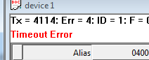
Modbus exception and error messages are displayed in red text on the second line of each window.
Modbus exception code
Modbus exception is an error returned by the device.
| Code | Name | Meaning |
|---|---|---|
| 01 | Illegal Function | The function code received in the query is not an operation permitted by the server (or slave). This may be because the function code is only applicable to newer devices and is not implemented in the selected unit. It may also indicate that the server (or slave) is in an incorrect state to handle this type of request, for example, because it is not configured and is being asked to return register values. |
| 02 | Illegal Data Address | The data address received in the query is not an address permitted by the server. More specifically, the combination of reference number and transmission length is invalid. For a controller with 100 registers, the PDU addresses the first register as 0 and the last register as 99. If the submitted request starts with a register address of 96 and has a register count of 4, the request will successfully operate (at least in terms of address) on registers 96, 97, 98, and 99. If the submitted request starts with a register address of 96 and has a register count of 5, the request will fail with an exception code 0x02 "Illegal Data Address" because it attempts to operate on registers 96, 97, 98, 99, and 100, and there is no register with an address of 100. |
| 03 | Illegal Data Value | The value contained in the query data field is not a value permitted by the server (or slave). This indicates an error in the structure of the remaining part of the complex request, such as an incorrect implied length. This does not mean that the data item submitted to be stored in the register has a value beyond the application's expectations, because the MODBUS protocol does not know the significance of any specific value for any specific register. |
| 04 | Server Device Failure | An unrecoverable error occurred when the server (or slave server) attempted to perform the requested operation. |
| 05 | Acknowledgement | Specifically used in conjunction with programming commands. The server (or slave) has accepted the request and is processing it, but this may take a long time. This response is returned to prevent timeout errors on the client (or master). The client (or master) can then issue a poll completion message to determine if processing is complete. |
| 06 | The server device is busy | Specifically used in conjunction with programming commands. The server (or slave) is processing a long-running program command. When the server (or slave) is idle, the client (or master) should retransmit the message later. |
| 0A | Gateway path unavailable | When used in conjunction with a gateway, indicates that the gateway cannot allocate an internal communication path from the input port to the output port to process the request. Usually means that the gateway is misconfigured or overloaded. |
| 0B | Gateway target device response failure | When used in conjunction with a gateway, indicates that no response was received from the target device. Usually means that the device does not exist on the network. |
Modbus poll error message
| Error information | Meaning |
|---|---|
| Timeout Error | No response received within the expected time. Check the following: Serial connection settings, such as baud rate, parity, data bits, stop bits, etc. Modbus mode, RTU or ASCII Slave ID response timeout TCP/IP connection response timeout Check if the Host and Port are consistent with the slave |
| Response Error | The response is not as expected. Different Slave ID. |
| CRC Error | The CRC value of the received response is incorrect. |
| Write Error | This is an error reported by the serial driver. This may occur if a USB/RS232/485 converter is used and the USB cable is unplugged. There are 4 types: Interrupt Condition Input/Output Error Serial Connection Error Output Buffer Overflow Write Error using TCP/IP connection is usually caused by a lost connection. |
| Read Error | This is an error reported by the serial driver. There are 6 types: Framing Error Character Buffer Overflow Parity Error Input Buffer Overflow Input/Output Error Interrupt Condition Read Error using TCP/IP connection is usually caused by a lost connection. |
| Insufficient bytes received | The response is not of the expected length. |
| Byte count error | The number of bytes in the response is incorrect. Compared to expectations. |
| Transaction ID error | It is used for transaction pairing, and the MODBUS server copies the transaction identifier of the request in the response. |
The software version is Modbus Poll 9.9.2.1690 Chinese version. Please comment and then download!!!



11
111
Download
1
很好
1111111
222
111111
11111
感谢分享
学习
xz
介绍的很详细,非常好用
xiazia
感谢
Download
谢谢
666
感谢
收下
谢谢楼主
最新版吗?给力!
感谢楼主
感谢楼主
感谢楼主
感谢楼主
感谢感谢
感谢楼主
介绍的很详细,非常好用
ceshi