
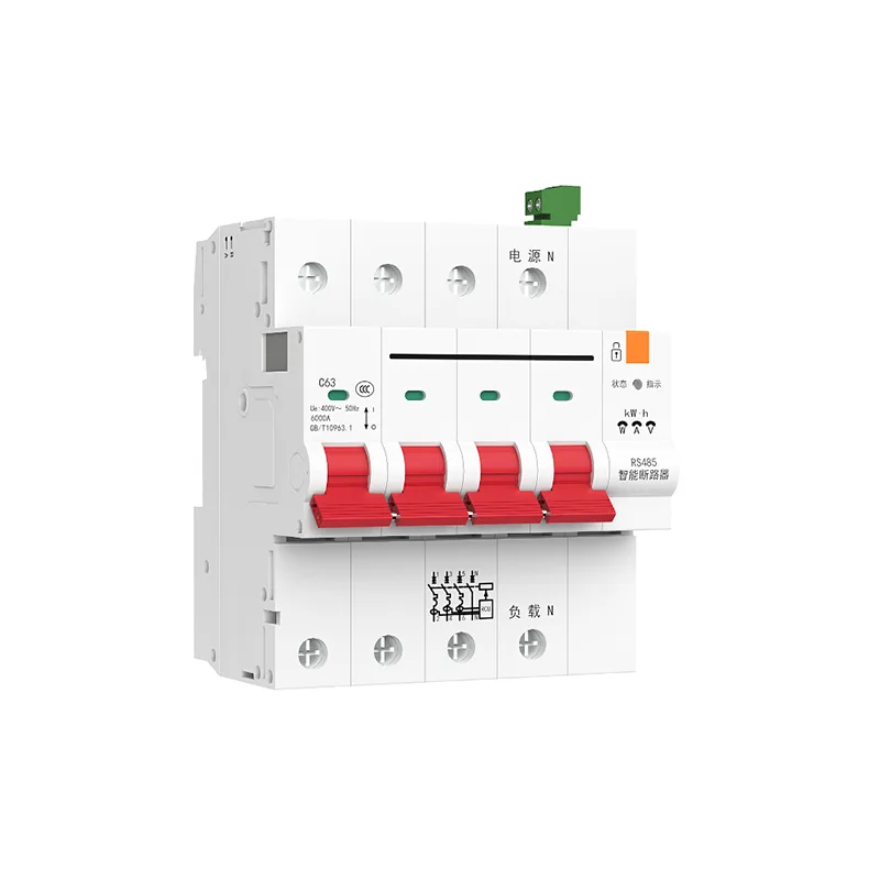
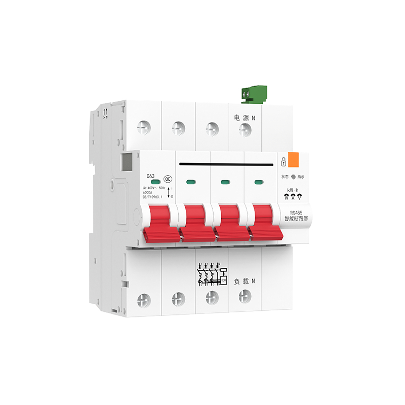
Safe and efficient management of electricity is crucial in modern households and industrial environments. With the continuous advancement of technology, intelligent metering protectors have become a key tool for ensuring electrical safety and improving energy efficiency. This device not only provides the basic functions of traditional protectors, but also incorporates a series of advanced technologies, making it a powerful tool for electrical management.
Opening Record 1
Opening record 3
Read real-time current A phase: 01 04 00 09 00 01 E1 C8 returns 01 04 02 XX XX+CRC XX XX as the current value (single-phase electrical reading A phase)
RS485signal communication
ThroughRS485Communication interface, The protector can communicate with other devices, Realize data sharing and remote monitoring. This enhances the intelligent management of devices, Provided convenience for maintenance and monitoring.
Undervoltage protection
Intelligent metering protector can detect voltage drop, Automatically disconnect the circuit, Prevent equipment damage caused by unstable voltage.
Remote opening and closing of switches
The remote control function allows users to control the opening and closing of the protector from any location through the network, This provides great convenience for remote management and emergency response.
Voltage loss protection
After power loss, The protector can automatically disconnect the circuit, Avoid sudden impacts or damage that may occur during power restoration.
Manual/automatic setting
Users can choose manual or automatic mode as needed, Flexible response to different usage scenarios.
Read real-time voltage
Real time monitoring of circuit voltage, Ensure the stable operation of the electrical system.
Remote locking/unlocking
Through remote control function, Users can lock or unlock the protector, Enhance security and management flexibility.
Technical parameters
- Rated working voltage: AC230V/400V.
- Extreme number: 1P/2P/3P/4P, Adapt to different installation requirements.
- Shell level current: Up to125A.
- Breaking ability: 6000AThe heightICSValue.
Leakage protection parameters
- Rated residual operating current: 10-90MACan be set.
- Action time: Less than or equal to0.1S, Ensure rapid response.
Power on function after power failure
- Automatic mode: Automatically close when no faults are detected, The closing time is less than3S.
- Manual mode: Will not automatically close, Provide users with manual control.
Application prospects
These advanced features of smart metering protectors make them a household, Essential equipment in commercial buildings and industrial applications. They not only improve the level of electrical safety, It also provides the possibility of energy conservation and intelligent management. Especially in industry4.0In the context of intelligent buildings, The intelligent and networked characteristics of this device will greatly improve the efficiency and flexibility of energy management.
With the development of technology and smart homes, The Rise of Smart Cities, Intelligent metering protectors are expected to play an increasingly important role in future power management and safety fields.
| Address | Command type | Function description | Data scope description | explain |
| Read coil operation Function code: Read(0X01) | ||||
| 0 (00001) | Position status coil | Current voltage malfunction | 1:have None 0:Position status coil | |
| 1 (00002) | Remote closing/opening | Close the switch | 1:Open the gate0:Position status coil | |
| 2 (00003) | Remote locking/unlocking | Lock buckle | 1:Unlock0:Position status coil | |
| 3 (00004) | Automatic control/manual | Automatic | 1:Manual operation0:Output coil operation | |
| Function code Write: Support broadcasting(0X05)(Output coil) | ||||
| 0 (00001) | Configuration reset | Output coil | 0xFF00 | |
| 1 (00002) | Remote closing/opening | Output coil | 0xFF00/0x0000 | |
| 2 (00003) | Remote locking/unlocking | Output coil | 0xFF00/0x0000 | |
| 3 (00004) | Automatic control/manual | Output coil | 0xFF00/0x0000 | |
| 4 (00005) | Record zeroing | After sending | 0xFF00 | Within seconds, the power supply of the incoming power supply will be counted and cleared10Output coil |
| 5 (00006) | Leakage test button | Maintain registers | 0xFF00 | |
| Function code Write more: Write alone(0X10) Read more (0X06) Maintain registers(0X03) | ||||
| 0 (40001) | Equipment address | The high byte is the subnet address and the low byte is the device address | Default | For broadcasting00 01 (0Subnet and broadcast have no response) Maintain registers |
| 1 (40002) | Baud rate | The default is | 1200 ~ 19200 | Maintain registers9600 |
| 2 (40003) | Overvoltage value | After read-write reset, it is | 250 ~300 (V) | After read-write reset, it is275 |
| 3 (40004) | Maintain registers | Undervoltage value | 150 ~200 (V) | After read-write reset, it is160 |
| 4 (40005) | Maintain registers | Overcurrent value | 1~100A(Company: 0.01A) | After read-write reset, it is6300 |
| 5 (40006) | Maintain registers | Leakage value | 10~90(Company: 1mA) | After read-write reset, it is30 |
| 6 (40007) | Maintain registers | Interface overheating value | 40~150(℃) | After read-write reset, it is80 |
| 7 (40008) | Maintain registers | Overload active power | 1000~13000single-phase30000three-phase(1W) | Read and write reset to the maximum value |
| 8 (40009) | Maintain registers | Electricity restriction degreeH | 1~999 999 999 | After read-write reset, it is0 |
| 9 (40010) | Maintain registers | Electricity restriction degreeL | (Company: 0.001Degree) | After read-write reset, it is0 |
| 10 (40011) | Maintain registers | Customer dataH | 0xFFFF | Read and write |
| 11 (40012) | Maintain registers | Customer dataL | 0xFFFF | Read and write |
| 12 (40013) | Maintain registers | Set position | Corresponding from low to high:0,Automatic control/manual;1,Remote locking/unlocking; | Read and write (synchronized with the corresponding coil) |
| 13 (40014) | hold register | remote closing/opening | 0xFF00/0x0000 | read and write (synchronized with the corresponding coil) |
| 14 (40015) | hold register | balance limit | 10~50000(degree) | read and write reset to10 |
| 15 (40016) | hold register | trip switch | corresponding from low to high:0,overvoltage;1,undervoltage;2,overcurrent3,leakage;4,overheating;5,overload;6,cost function switch;7,low balance trip switch | read and write, each individually defined as 1 is on,0after reset, it is off3F(63) |
| 16 (40017) | hold register | Overvoltage action time | 0~10000(Company: 0.1s) | After read-write reset, it is0 |
| 17 (40018) | Maintain registers | Undervoltage action time | 0~10000(Company: 0.1s) | After read-write reset, it is0 |
| 18 (40019) | Maintain registers | Leakage action time | 0~10000(Company: 0.1s) | After read-write reset, it is0 |
| 19 (40020) | Maintain registers | Overcurrent action time | 0~10000(Company: 0.1s) | After read-write reset, it is0 |
| 20 (40021) | Maintain registers | Active overload action time | 0~10000(Company: 0.1s) | After read-write reset, it is0 |
| 21 (40022) | Maintain registers | Overtemperature action time | 0~10000(Company: 0.1s) | After read-write reset, it is0 |
| 22 (40023) | Maintain registers | Module reporting time coefficient | 15(Company: 0.02s) | Read and write reset to initial value |
| 28 (40029) | Maintain registers | Voltage calibration coefficient | 17609 | Read and write reset to initial value |
| 29 (40030) | Maintain registers | Current calibration coefficient | 847 | Read and write reset to initial value |
| 30 (40031) | Maintain registers | Active power calibration coefficient | 2289 | Read and write reset to initial value |
| 31 (40032) | Maintain registers | Electricity calibration coefficient | 1964(For the coefficient of probability*0.858Double) | Read and write reset to initial value |
| Input register Function code(0X4) | ||||
| 0 (30001) | Input register | Switch on/off status | High byte: Local locking: 0x01,No lock: 0Low byte: Open the gate: 0xF,Close the switch: 0xF0 | Read only |
| 1 (30002) | Input register | Opening record1 | F: None 1: Overcurrent 2: electric leakage 3: Overheating 4: Overload 5: overvoltage 6: Undervoltage 7: long-range 8: Module9: Loss of pressure A: Lock buckleB: Power rationing 0: Local | Read only, XXXX=3210Half byte is the smallest unit. 3 is the reason for the last nine disconnections recorded. 2 is the reason for the tenth disconnections recorded before. 1 is the reason for the eleventh disconnections recorded before. 0 is the reason for the twelfth disconnections recorded before |
| 2 (30003) | Input register | Opening record2 | F: None 1: Overcurrent 2: electric leakage 3: Overheating 4: Overload 5: Overvoltage 6: Undervoltage 7: long-range 8: Module9: Loss of pressure A: Lock buckleB: Power rationing 0: Local | Read only, XXXX=7654Half byte is the smallest unit. 7 is the reason for the fifth disconnection before recording. 6 is the reason for the sixth disconnection before recording. 5 is the reason for the seventh disconnection before recording. 4 is the reason for the eighth disconnection before recording |
| 3 (30004) | Input register | Opening record3 | F: None 1: Overcurrent 2: electric leakage 3: Overheating 4: Overload 5: Overvoltage 6: Undervoltage 7: long-range 8: Module9: Loss of pressure A: Lock buckleB: Power rationing 0: Local | Read only, XXXX=BA98Half byte is the smallest unit. B is the record of the latest disconnection reason. A is the reason for the second disconnection before recording. 9 is the reason for the third disconnection before recording. 8 is the reason for the fourth disconnection before recording |
| 4 (30005) | Input register | FrequencyF | 0~1000(Company: 0.1Hz) | Read only |
| 5 (30006) | Input register | Leakage currentL | 0~1000(Company: 1mA) | Read only |
| 6 (30007) | Input register | NTemperature of the connecting wire pillar | 0~200(Company: ℃),-40Next is the actual temperature | Read only |
| 7 (30008) | Input register | ATemperature of the connecting wire pillar | 0~200(Company: ℃),-40Next is the actual temperature | Read only |
| 8 (30009) | Input register | AEffective value of phase voltageU | 0~600(Company: 1V) | Read only |
| 9 (30010) | Input register | AEffective value of phase currentI | 0~0xFFFF(Company: 0.01A) | Read only |
| 10 (30011) | Input register | APhase power factorPf | 0~100(Company: 0.01) | Read only |
| 11 (30012) | Input register | APhase active powerP | 0~0xFFFF(Company: 1W) | Read only |
| 12 (30013) | Input register | APhase reactive powerQ | 0~0xFFFF(Company: VAR) | Read only |
| 13 (30014) | Input register | ARelative powerS | 0~0xFFFF(Company: VA) | Read only |
| 14 (30015) | Input register | High active power outputH | 1~999 999 999 | Read only |
| 15 (30016) | Input register | Active measurement low wordL | (Company: 0.001Degree) | Read only |
| 16 (30017) | Input register | BTemperature of the connecting wire pillar | 0~200(Company: ℃),-40Next is the actual temperature | Read only |
| 17 (30018) | Input register | BEffective value of phase voltageU | 0~600(Company: 1V) | Read only |
| 18 (30019) | Input register | BEffective value of phase currentI | 0~0xFFFF(Company: 0.01A) | Read only |
| 19 (30020) | Input register | BPhase power factorPf | 0~100(Company: 0.01) | Read only |
| 20 (30021) | Input register | BPhase active powerP | 0~0xFFFF(Company: 1W) | Read only |
| 21 (30022) | Input register | BPhase reactive powerQ | 0~0xFFFF(Company: VAR) | Read only |
| 22 (30023) | Input register | BRelative powerS | 0~0xFFFF(Company: VA) | Read only |
| 23 (30024) | Input register | Reason for disconnection | Corresponding from low to high:0,Local;1,Overcurrent;2,electric leakage;3,Overheating;4,Overload;5,Overvoltage;6,Undervoltage;7,long-range;8,Module;9,Loss of pressure;10Lock buckle;11,Power rationing;12,reserve;13,reserve;14,reserve;15,None; | Read only |
| 24 (30025) | Input register | spare | Read only | |
| 25 (30026) | Input register | CTemperature of the connecting wire pillar | 0~200(Company: ℃),-40Next is the actual temperature | Read only |
| 26 (30027) | Input register | CEffective value of phase voltageU | 0~600(Company: 1V) | Read only |
| 27 (30028) | Input register | CEffective value of phase currentI | 0~0xFFFF(Company: 0.01A) | Read only |
| 28 (30029) | Input register | CPhase power factorPf | 0~100(Company: 0.01) | Read only |
| 29 (30030) | Input register | CPhase active powerP | 0~0xFFFF(Company: 1W) | Read only |
| 30 (30031) | Input register | CPhase reactive powerQ | 0~0xFFFF(Company: VAR) | Read only |
| 31 (30032) | Input register | CRelative powerS | 0~0xFFFF(Company: VA) | Read only |
| 32 (30033) | Input register | spare | Read only | |
| 33 (30034) | Input register | spare | read-only | |
| 34 (30035) | Input register | Combined active powerP | 0~0xFFFF(Company: 1W) | Read only |
| 35 (30036) | Input register | Combined reactive powerQ | 0~0xFFFF(Company: VAR) | Read only |
| 36 (30037) | Input register | Combined apparent powerS | 0~0xFFFF(Company: VA) | Read only |
| 37 (30038) | Input register | High combined active powerH | 1~999 999 999 | Read only |
| 38 (30039) | Input register | Low word for combined active power measurementL | (Company: 0.001Degree) | Read only |
| 18 (40019) | Maintain registers | Leakage action time | 0~10000(Company: 0.1s) | After read-write reset, it is0 |
| 19 (40020) | Maintain registers | Overcurrent action time | 0~10000(Company: 0.1s) | After read-write reset, it is0 |
| 20 (40021) | Maintain registers | Active overload action time | 0~10000(Company: 0.1s) | After read-write reset, it is0 |
| 21 (40022) | Maintain registers | Overtemperature action time | 0~10000(Company: 0.1s) | After read-write reset, it is0 |
| 22 (40023) | Maintain registers | Module reporting time coefficient | 15(Company: 0.02s) | Read and write reset to initial value |
| 28 (40029) | Maintain registers | Voltage calibration coefficient | 17609 | Read and write reset to initial value |
| 29 (40030) | Maintain registers | Current calibration coefficient | 847 | Read and write reset to initial value |
| 30 (40031) | Maintain registers | Active power calibration coefficient | 2289 | Read and write reset to initial value |
| 31 (40032) | Maintain registers | Electricity calibration coefficient | 1964(For the coefficient of probability*0.858Double) | Read and write reset to initial value |
| Input register Function code(0X4) | ||||
| 0 (30001) | Input register | Switch on/off status | High byte: Local locking: 0x01,No lock: 0Low byte: Open the gate: 0xF,Close the switch: 0xF0 | Read only |
| 1 (30002) | Input register | Opening record1 | F: None 1: Overcurrent 2: electric leakage 3: Overheating 4: Overload 5: Overvoltage 6: Undervoltage 7: long-range 8: Module9: Loss of pressure A: Lock buckleB: Power rationing 0: Local | Read only, XXXX=3210Half byte is the smallest unit. 3 is the reason for the last nine disconnections recorded. 2 is the reason for the tenth disconnections recorded before. 1 is the reason for the eleventh disconnections recorded before. 0 is the reason for the twelfth disconnections recorded before |
| 2 (30003) | Input register | Opening record2 | F: None 1: Overcurrent 2: electric leakage 3: Overheating 4: Overload 5: Overvoltage 6: Undervoltage 7: long-range 8: Module9: Loss of pressure A: Lock buckleB: Power rationing 0: Local | Read only, XXXX=7654Half byte is the smallest unit. 7 is the reason for the fifth disconnection before recording. 6 is the reason for the sixth disconnection before recording. 5 is the reason for the seventh disconnection before recording. 4 is the reason for the eighth disconnection before recording |
| 3 (30004) | Input register | Opening record3 | F: None 1: Overcurrent 2: electric leakage 3: Overheating 4: Overload 5: Overvoltage 6: Undervoltage 7: long-range 8: Module9: Loss of pressure A: Lock buckleB: Power rationing 0: Local | Read only, XXXX=BA98Half byte is the smallest unit. B is the record of the latest disconnection reason. A is the reason for the second disconnection before recording. 9 is the reason for the third disconnection before recording. 8 is the reason for the fourth disconnection before recording |
| 4 (30005) | Input register | FrequencyF | 0~1000(Company: 0.1Hz) | read-only |
| 5 (30006) | Input register | Leakage currentL | 0~1000(Company: 1mA) | Read only |
| 6 (30007) | Input register | NTemperature of the connecting wire pillar | 0~200(Company: ℃),-40Next is the actual temperature | Read only |
| 7 (30008) | Input register | ATemperature of the connecting wire pillar | 0~200(Company: ℃),-40Next is the actual temperature | Read only |
| 8 (30009) | Input register | AEffective value of phase voltageU | 0~600(Company: 1V) | Read only |
| 9 (30010) | Input register | AEffective value of phase currentI | 0~0xFFFF(Company: 0.01A) | Read only |
| 10 (30011) | Input register | APhase power factorPf | 0~100(Company: 0.01) | Read only |
| 11 (30012) | Input register | APhase active powerP | 0~0xFFFF(Company: 1W) | Read only |
| 12 (30013) | Input register | APhase reactive powerQ | 0~0xFFFF(Company: VAR) | Read only |
| 13 (30014) | Input register | ARelative powerS | 0~0xFFFF(Company: VA) | Read only |
| 14 (30015) | Input register | High active power outputH | 1~999 999 999 | Read only |
| 15 (30016) | Input register | Active measurement low wordL | (Company: 0.001Degree) | Read only |
| 16 (30017) | Input register | BTemperature of the connecting wire pillar | 0~200(Company: ℃),-40Next is the actual temperature | Read only |
| 17 (30018) | Input register | BEffective value of phase voltageU | 0~600(Company: 1V) | Read only |
| 18 (30019) | Input register | BEffective value of phase currentI | 0~0xFFFF(Company: 0.01A) | Read only |
| 19 (30020) | input register | BPhase power factorPf | 0~100(Company: 0.01) | Read only |
| 20 (30021) | Input register | BPhase active powerP | 0~0xFFFF(Company: 1W) | Read only |
| 21 (30022) | Input register | BPhase reactive powerQ | 0~0xFFFF(Company: VAR) | Read only |
| 22 (30023) | Input register | BRelative powerS | 0~0xFFFF(Company: VA) | Read only |
| 23 (30024) | Input register | Reason for disconnection | Corresponding from low to high:0,Local;1,Overcurrent;2,electric leakage;3,Overheating;4,Overload;5,Overvoltage;6,Undervoltage;7,long-range;8,Module;9,Loss of pressure;10Lock buckle;11,Power rationing;12,reserve;13,reserve;14,reserve;15,None; | Read only |
| 24 (30025) | Input register | spare | Read only | |
| 25 (30026) | Input register | CTemperature of the connecting wire pillar | 0~200(Company: ℃),-40Next is the actual temperature | Read only |
| 26 (30027) | Input register | CEffective value of phase voltageU | 0~600(Company: 1V) | Read only |
| 27 (30028) | Input register | CEffective value of phase currentI | 0~0xFFFF(Company: 0.01A) | Read only |
| 28 (30029) | Input register | CPhase power factorPf | 0~100(Company: 0.01) | Read only |
| 29 (30030) | Input register | CPhase active powerP | 0~0xFFFF(Company: 1W) | Read only |
| 30 (30031) | input register | CPhase reactive powerQ | 0~0xFFFF(Company: VAR) | Read only |
| 31 (30032) | Input register | CRelative powerS | 0~0xFFFF(Company: VA) | Read only |
| 32 (30033) | Input register | spare | Read only | |
| 33 (30034) | Input register | spare | Read only | |
| 34 (30035) | Input register | Combined active powerP | 0~0xFFFF(Company: 1W) | Read only |
| 35 (30036) | Input register | Combined reactive powerQ | 0~0xFFFF(Company: VAR) | Read only |
| 36 (30037) | Input register | Combined apparent powerS | 0~0xFFFF(Company: VA) | Read only |
| 37 (30038) | Input register | High combined active powerH | 1~999 999 999 | Read only |
| 38 (30039) | Input register | Low word for combined active power measurementL | (Company: 0.001Degree) | Read only |
Note::
1, The default annotation type is16Bit unsigned integer
2, In the locked state, The switch cannot be closed for operation.
3, In unlocked state, The switch can be closed for operation.
Product factory communication parameter settings:
Equipment address: 1
Baud rate: 9600
Parity check: No verification
CRCVerification: 16PositionCRCVerification, Low position in front
Stop position: 1
Format description:
Write coils
| Byte number | 01 | 02 | 03 ~ 04 | 05 ~ 06 | 07 ~ 08 |
| Function | Equipment address | Function code05 | Coil address | Operation code | CRCVerification |
| Byte number | 01 | 02 | 03 ~ 04 | 05 ~ 06 | 07 ~ 08 |
| Function | Equipment address | Function code05 | Coil address | Operation code | CRCVerification |
Reading coil
| Byte number | 01 | 02 | 03 ~ 04 | 05 ~ 06 | 07 ~ 08 |
| Function | Equipment address | Function code01 | Starting address | Data length | CRCVerification |
| Byte number | 01 | 02 | 03 | 04 | 05 ~ 06 |
| Function | Equipment address | Function code01 | Byte length | Coil status | CRCVerification |
Read and hold registers
| Byte number | 01 | 02 | 03 ~ 04 | 05 ~ 06 | 07 ~ 08 |
| Function | Equipment address | Function code03 | Register address | Data length | CRCVerification |
| Byte number | 01 | 02 | 03 | 04 ~ 05 | ……… | 2n+2 ~ 2n+3 | 2n+4 ~ 2n+5 |
| Function | Equipment address | Function code03 | Byte length | data data Verification1 | ……… | ….respondn | CRCRead input register |
Function
| Equipment address | 01 | 02 | 03 ~ 04 | 05 ~ 06 | 07 ~ 08 |
| Function code | Register address | Data length04 | Verification | Read | CRCByte number |
| Equipment address | 01 | 02 | 03 | 04 ~ 05 | ……… | 2n+2 ~ 2n+3 | 2n+4 ~ 2n+5 |
| Function code | Byte length | data data Verification04 | byte length | data1 | ……… | ….datan | CRCVerification |
Write hold register
| Byte number | 01 | 02 | 03 ~ 04 | 05 ~ 06 | 07 | 08 ~ 09 | ……. | 2n+6 ~ 2n+7 | 2n+8 ~2n+9 |
| Function | Equipment address | Function code10 | Register address | Data length | Byte length | data data Verification1 | …… | ….Readn | CRCByte number |
| Equipment address | 01 | 02 | 03 ~ 04 | 05 ~ 06 | 07 ~ 08 |
| Function code | Register address | Data length10 | Verification | respond | CRCExample |
Or:
Open the gate: 01 05 00 01 FF 00 DD FAOr01 06 00 0D FF 00 59 F9
Read real-time voltage phase A: 01 05 00 01 00 00 9C 0A return01 06 00 0D 00 00 18 09
For voltage value: 01 04 00 08 00 01 B0 08Single phase electrical reading A phase01 04 02 XX XX+CRC XX XXRead real-time voltage phase B (Read real-time voltage phase C)
Read real-time current phase A: 01 04 00 11 00 01 61 CF
return: 01 04 00 1A 00 01 10 0D
For the current value: 01 04 00 09 00 01 E1 C8Single phase electrical reading A phase01 04 02 XX XX+CRC XX XXRead real-time current B phase (Read real-time current phase C)
Read electricity consumption: 01 04 00 12 00 01 91 CF
return: 01 04 00 1B 00 01 41 CD
Electricity consumption degree: 01 04 00 0E 00 02 10 08Or01 04 04 XX XX XX XX+CRC XX XX XX XXUnified closing, broadcasting and closing
Or: 01 04 00 25 00 02 60 00
The broadcast command does not return: 00 05 00 01 FF 00 DC 2BUnified disconnection, broadcasting disconnection00 06 00 0D FF 00 58 28 (Or)
Read real-time active power phase A: 00 05 00 01 00 00 9D DBreturn00 06 00 0D 00 00 19 D8
For active power: 01 04 00 0B 00 01 40 08Single phase electrical reading A phase01 04 02 XX XX+CRC XX XXRead real-time active power phase B (Read real-time active power phase C)
Read real-time active total power: 01 04 00 14 00 01 71 CE
Three phase sum: 01 04 00 1D 00 01 A1 CC
Read real-time reactive power phase A (return) : 01 04 00 22 00 01 91 C0
For reactive power: 01 04 00 0C 00 01 F1C9Single phase electrical reading A phase01 04 02 XX XX+CRC XX XXRead real-time reactive power phase B (Single phase electrical reading A phase)
Read real-time reactive power phase B: 01 04 00 15 00 01 20 0E
Read real-time reactive power phase C: 01 04 00 1E 00 01 51 CC
Read real-time reactive power total power (Three phase sum) : 01 04 00 23 00 01 C0 00
Read real-time apparent power phase A: 01 04 00 0D 00 01 A0 09return01 04 02 XX XX+CRC XX XXFor apparent power (Single phase electrical reading A phase)
Read real-time apparent power phase B: 01 04 00 16 00 01 D0 0E
Read real-time apparent power phase C: 01 04 00 1F 00 01 00 0C
Read real-time apparent total power (Three phase sum) : 01 04 00 24 00 01 71 C1
Read power factor A phase: 01 04 00 0A 00 01 11 C8return01 04 02 XX XX+CRC XX XXPower factor
Read power factor B phase: 01 04 00 13 00 01 C0 0F
Read power factor C phase: 01 04 00 1C 00 01 F0 0C
Read real-time temperature of phase A: 01 04 00 07 00 01 80 0Breturn01 04 02 XX XX+CRC XX XXFor temperature values (Reduce40For actual temperature)
Read real-time temperature phase B: 01 04 00 10 00 01 30 0F
Read real-time temperature C phase: 01 04 00 19 00 01 E0 0D
Read real-time temperature N-phase: 01 04 00 06 00 01 D1 CB (Read N phase for products that only measure onboard temperature)
Reading frequency: 01 04 00 04 00 01 70 0B return01 04 02 XX XX+CRC XX XXFor frequency
Read the leakage value: 01 04 00 05 00 01 21 CB return01 04 02 XX XX+CRC XX XXFor leakage value


Leave a Reply