

Coil and register
Introduction earlier Modbus The content mentions coils multiple times (coil) And registers (register) The concept, especially Modbus function code In the middle,The objects of operation are basically coils and registers.
in Modbus The reason why they are still referred to as coils and registers in the protocol, It's entirely due to historical reasonsIn PLC Application areas, One coil represents one PLC output point, Also known as output relay. Change the output state of the relay by controlling the conduction of the coil, Realize weak current control and strong current.
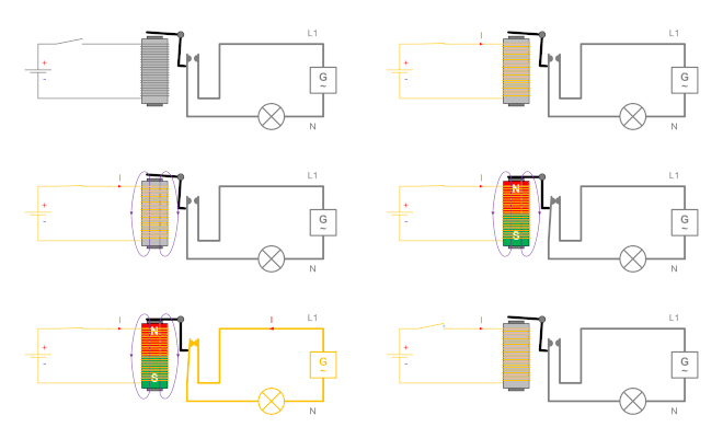
but in fact, In today's Modbus In the device, They all just correspond to a memory area. among which, Coil representative position operation (bit) , Representing a Boolean variable; Register represents word operation (word) , Representing an integer variable (Of course, it can also be done by combining multiple words, Representing floating-point numbers and other composite data structures). in Modbus in the agreement, word(word) The length is 16 Position, i.e 2 bytes.
Description of Register Types
in Modbus in the agreement, All data is stored in registers. Based on the type of data stored and their respective read-write characteristics, The register can be divided into four parts, These four parts can be continuous or discontinuous, Completely determined by the developer.
The following table shows the meanings of four types of registers and their relationship with PLC The analogy.
| Register type | meaning | PLC | Example |
|---|---|---|---|
| Coil status (Coil Status) | output port (readable and writable) | DO (digital output) | Electromagnetic valve output, LED display |
| Discrete input state (Input Status) | Input port (read-only) | DI (Digital input) | DIP switch, Micro Switch |
| holding register (Holding Register) | output parameters (readable and writable) | AO (Analog output) | PID operating parameters, Threshold upper and lower limits |
| input register (Input Register) | input parameters (read-only) | AI (Analog input) | Sensor data input |
Register Address Allocation
Modbus The allocation of register addresses is shown in the following table, Also referenced PLC Method for allocating register addresses.
| Register type | registerPLCaddress | registerModbusContract Address | Abbreviation |
|---|---|---|---|
| Coil status | 00001~09999 | 0000H~FFFFH | 0x |
| Discrete input state | 10001~19999 | 0000H~FFFFH | 1x |
| holding register | 40001~49999 | 0000H~FFFFH | 4x |
| input register | 30001~39999 | 0000H~FFFFH | 3x |
In this table PLC The address can be understood as Modbus Variations of Protocol Address, On the touch screen and PLC Widely used in programming.
- register PLC The address refers to the address stored in the controller, These controllers can be PLC, It can also be a touch screen, Or text display. PLC The address is generally described in decimal system, common 5 Position,The first digit represents the register type.
- register Modbus Protocol address refers to the register addressing address used during communication, for example PLC address 40001 Corresponding addressing address 0x0000, 40002 Corresponding addressing address 0x0001. Register addressing addresses are generally described in hexadecimal format.
Careful you will find, PLC register address 40003 The corresponding protocol address is 0x0002, PLC register address 30003 The corresponding protocol address is also 0x0002, Although two identical ones are used for communication Modbus Contract Address, But because the function codes of different registers are not the same, Therefore, there is no access conflict.


Leave a Reply