

Work Mode
Modbus Working based on master-slave mode. In a network, Modbus Protocol through main device (client) And from the device (Server) The request response mechanism between them is used to exchange information.
The following figure shows a typical Modbus Internet, one of them master Device (client) Control one or more slave Device (server) .
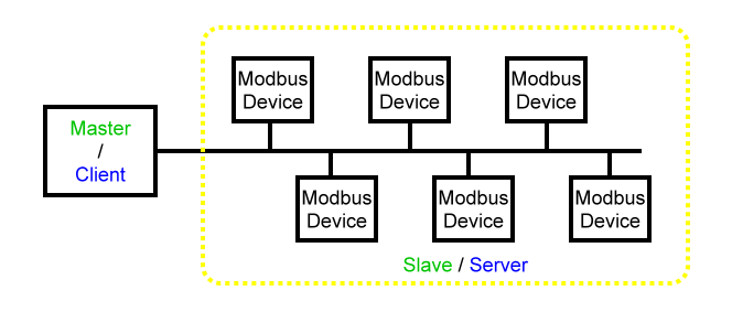
In standard Modbus In the networkhave 1 Primary devices and maximum 31 From device.
Communication characteristics
The working principle of master and slave devices has the following characteristics:
- Only one primary device can be connected to the network at a time;
- Only the master device can initiate communication and send requests to the slave devices;
- The master device can access each slave device separately using a dedicated address, You can also use the address 0 Simultaneously access all slave devices;
- The slave device can only send responses to the master device;
- The slave device cannot initiate communication with the master device or other slave devices.
communication mode
Modbus The protocol supports two communication modes for exchanging information:
- Unicast Mode —— The master device accesses the slave device through a dedicated address, Processing requests from devices, Then send a response to the main device.
- broadcast mode —— The main device passes through the address 0 Access all slave devices, In this mode, The device does not respond to broadcast messages. (Therefore, The request instruction for broadcast mode must be Modbus Write instructions in standard functions)
Response time
Response time refers to the time required for the slave device to respond to requests sent by the master device. among which Modbus The numerical value of the agreement:
- typical value < 10 ms (90% Information exchange)
- The maximum value is approximately 700 ms, Therefore, it is recommended to send one after completion Modbus Pause after request 1 Continue for a second.
data exchange
Modbus The protocol supports two types of data:
- Single bit
- register (16 Position)
The specific bit and register definitions are determined by the slave device.
address
Use Modbus The message exchanged by the protocol contains the address of the data to be processed. Each register has a register number, Each type of data (Bit or register) Everyone has one 16 Location address.
in Modbus According to the agreement PDU In the middle,Require all coil or register addresses to be from 0 Start calculation. Therefore, the n The address of the register is n-1. for example, the 12000 The address of the register is 0x2EDF (11999) .
frame
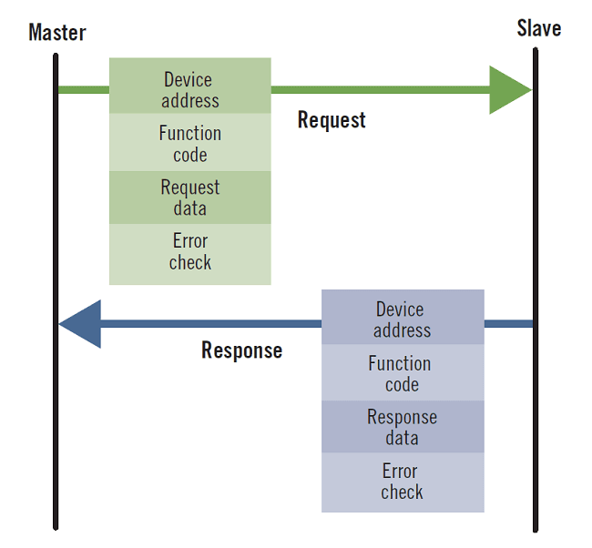
Use Modbus All frames exchanged by the protocol (ADU) The maximum is 256 byte (ASCII Double the format) , including 4 Individual domain:
| domain | definition | size (RTU format) | Description |
|---|---|---|---|
| 1 | From device number (address) | 1 bytes | The destination address of the request - 0 : broadcast (Involving all devices) - 1-247 : unicast, From the unique address of the device |
| 2 | Function code | 1 bytes | refer to Modbus function code |
| 3 | data | 0 to 252 bytes | Request data (Or respond to data) |
| 4 | checksum | 2 bytes | CRC checksum (ASCII for LRC) |
The following figure shows the frame exchange process in the master slave working model.
network topology
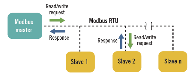
Modbus RTU
Modbus RTU Usually based on RS-485 Serial communication link, RS-485 The bus wiring specification stipulates that it must be a bus topology structure. In actual wiring, Usually, hand in hand daisy chain wiring is used. for example, Slave 1/2/3 Santai RS-485 Device, Slave1 of 485+ access Slave2 of 485+ port, Slave2 of 485+ Connect again to Slave3 of 485+ port, and so on, 485- The wiring method and 485+ Same.
Modbus TCP
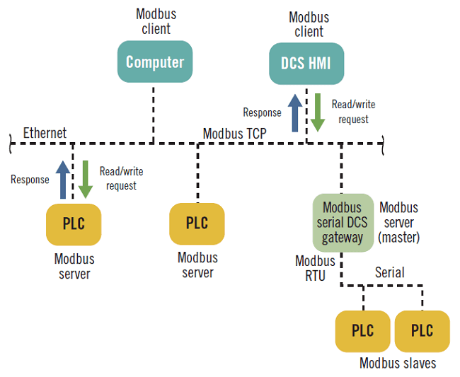
Compared to using a serial link Modbus RTU, Modbus TCP Based on Ethernet communication, Therefore, its network topology structure is more flexible. Construction of one master and multiple slaves on a serial link, Evolved into a multi client/multi server construction model.
Use Modbus TCP, Main station equipment (client) can be passed through IP Address found Modbus From the device (Server) , and pass through Modbus Gateway connected to another Modbus RTU Internet.


Leave a Reply