
Complete Manual for Modbus Exception Response Codes and Troubleshooting: A Comprehensive Analysis from 01 to 11
Keywords:Modbus Exception Code, Modbus Fault Diagnosis, Modbus Error Code, Modbus Exception Code, Modbus Communication Fault
In the field of industrial automation, Modbus communication faults are one of the most troublesome issues for engineers. When the master station sends a request, the slave station returns not normal data but an "exception response" - indicating that there is no problem with the communication link, but an error has occurred in the business logic layer. Understanding the meaning, triggering conditions, and troubleshooting methods of each exception code is a compulsory course for every automation engineer.
This article will start from the Modbus protocol specification (V1.1b3) and combine real industrial field cases to deeply analyze the triggering mechanisms, troubleshooting processes, and solutions for all 11 standard exception codes. Whether you are a novice who is new to Modbus or an experienced engineer who wants to systematically organize your knowledge, you can find practical references in this article.
I. Basic Mechanism of Modbus Exception Response
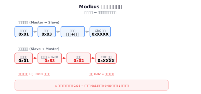
1.1 Normal Response vs Exception Response
In the Modbus protocol, the master station (Master/Client) sends a request message to the slave station (Slave/Server), and the slave station processes and returns a response message. When everything is normal, the function code in the response is exactly the same as the function code in the request:
请求: [从站地址] [功能码 0x03] [起始地址高字节] [起始地址低字节] [寄存器数量高字节] [寄存器数量低字节] [CRC低] [CRC高]
正常响应: [从站地址] [功能码 0x03] [字节数] [数据...] [CRC低] [CRC高]
When the slave station cannot process the request normally, it sets the highest bit (bit 7) of the function code to 1 and places a byte of exception code in the data area. That is to say,Exception Function Code = Request Function Code + 0x80. For example, when the request function code 0x03 encounters an exception, the response function code becomes 0x83.
异常响应报文结构(RTU 模式):
[从站地址] [功能码+0x80] [异常码] [CRC低] [CRC高]

示例 - 请求不存在的寄存器地址:
请求: 01 03 27 10 00 01 [CRC]
异常响应: 01 83 02 [CRC]
→ 功能码 0x83 = 0x03 + 0x80,异常码 0x02 = 非法数据地址
1.2 Judgment Logic for Abnormal Responses
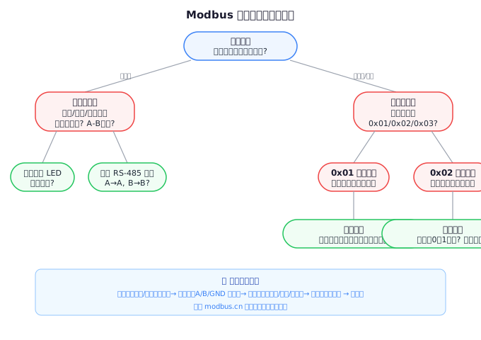
When you view the data returned by the slave station in debugging tools (such as Modbus Poll, ModScan), it is very simple to determine whether it is an abnormal response:
- Check if the response function code is greater than 0x80 (i.e., the highest bit is 1)
- If the function code > 0x80, the second byte is the abnormal code
- Determine the error type by referring to the table based on the abnormal code
In programming implementation, the detection logic is as follows:
// C 语言异常响应检测示例
if (response_function_code & 0x80) {
    uint8_t exception_code = response_data[0];
    switch (exception_code) {
        case 0x01: // 非法功能码
        case 0x02: // 非法数据地址
        case 0x03: // 非法数据值
        // ... 其他异常码处理
    }
}
II. Complete Analysis of 11 Standard Abnormal Codes
The Modbus protocol specification defines 11 standard abnormal codes (0x01 ~ 0x0B). Below, we will deeply analyze the meaning, triggering conditions, typical scenarios, and troubleshooting methods of each abnormal code one by one.
Abnormal Code 0x01 — Illegal Function
Meaning:The slave does not support the requested function code. This is one of the most common exception codes, typically occurring when the master uses a function code that is not implemented by the slave.
Typical triggering scenarios:
- Function code out of range:The master sends a function code 0x14 (read file records), but the slave only implements 0x03, 0x04, 0x06, and 0x10
- PLC model not supported:Some low-end PLCs only support 0x03 and 0x06, and attempting to use 0x10 (write multiple registers) will return 0x01
- Device configuration error:Some devices' Modbus implementations enable/disable function codes through configuration switches. If the corresponding function is disabled, it will also return 0x01
- Gateway conversion issue:The Modbus TCP to RTU gateway may not support transparent transmission of certain function codes
Troubleshooting steps:
- Refer to the device manual to confirm which function codes are supported by the slave
- Use tools such as Modbus Poll to test function codes one by one to narrow down the scope of the problem
- Check the function code filtering configuration of the gateway/converter
- If using a self-developed program, confirm whether the function code constant definition is correct
Actual case:In a water treatment project, the host computer uses function code 0x17 (read/write multiple registers) to operate the Schneider PM800 power meter, but always returns an error code 0x01. Upon checking the manual, it is found that the PM800 only supports 0x03 and 0x10. Solution: Split the operation into two steps: first read with 0x03, then write with 0x10.
Error code 0x02 - Illegal Data Address
Meaning:The requested register address does not exist in the slave. This is the most common error code encountered by engineers during the debugging stage.
Typical triggering scenarios:
- Address offset error:The Modbus address of the PLC usually starts from 0, but the host computer may configure an address starting from 1
- Register range overflow:The requested starting address + quantity exceeds the maximum register range of the slave
- Address mapping error:Some devices use different address mapping tables (e.g., some devices map 40001 to internal address 0, while others map it to 1)
- Data type confusion:32-bit floating-point numbers occupy 2 registers, and requesting only 1 register may trigger an out-of-bounds error
Troubleshooting steps:
- Use the 0x03 function code to read from address 0 one by one to determine the valid address range
- Confirm whether the address in the device manual is a "protocol address" or a "PLC address" - the two may differ by 1
- For 32-bit data, ensure that the number of requested registers is even
- Check whether the address in the message is in big-endian or little-endian byte order
Exception code 0x03 - Illegal Data Value
Meaning:The value in the request is outside the allowable range of the slave. This does not involve an address issue, but rather a "value" issue.
Typical triggering scenarios:
- Write value out of range:The temperature setting value range is 0~100°C, but the master station writes 150
- Number of registers is invalid:The "Number of Registers" field of the 0x10 function code is 0 or exceeds the maximum value that the slave can handle at a single time (usually 123)
- Byte count mismatch:The "Byte Count" field of the 0x10 function code is inconsistent with "Number of Registers × 2"
- Message length error:The actual length of the entire message does not match the length declared in the header
Troubleshooting steps:
- Focus on checking the message structure of 0x10 (writing multiple registers) - this is the scenario where errors are most likely to occur
- Verify whether the equation "byte count = register count × 2" holds true.
- Confirm whether the written value falls within the range specified in the device manual.
- For 0x06 (writing a single register), check the range of the written value (0x0000 ~ 0xFFFF).
Exception code 0x04 — Slave Device Failure.
Meaning:An unrecoverable internal error occurred when the slave device was processing the request. This is a "catch-all" exception code indicating a serious problem with the slave device itself.
Typical triggering scenarios:
- EEPROM/Flash write failure:The slave device fails to write configuration to non-volatile memory.
- Sensor failure:The sensor connected to the slave device is damaged and unable to provide valid readings.
- Internal communication failure:Communication abnormality between the main control chip and peripherals within the slave station
- File system error:Function codes (0x14, 0x15) involving file operations encounter file system abnormalities
Troubleshooting steps:
- Check the stability of the power supply to the slave device
- Observe the status of the LED indicator lights on the slave station (usually there is a fault light)
- Try to power off and restart the slave station
- Contact the device manufacturer for diagnostic tools or firmware upgrades
Exception code 0x05 — Acknowledge
Meaning:The slave station has accepted the request, but it requires a longer time to process. This is not an error, but a "please wait" signal. The slave station is executing an operation and will return a normal response once processing is complete.
Typical triggering scenarios:
- EEPROM writing takes a long time:Non-volatile memory writing for some devices may take hundreds of milliseconds
- Firmware upgrade operation:Writing to program memory takes a long time
- Motor executing action:The slave is executing a physical action (such as valve switching)
Programming suggestion:After receiving the exception code 0x05, the master should not immediately retry or report an error, but should wait for an appropriate time before re-polling. It is recommended to use a state machine for processing:
// 异步处理确认响应的状态机
enum { IDLE, WAITING, POLLING } state = IDLE;

void modbus_handler(uint8_t func, uint8_t* data) {
    if (func & 0x80) {
        if (data[0] == 0x05) {
            state = POLLING;
            start_poll_timer(500); // 500ms 后重新查询
        }
    }
}
Exception code 0x06 — Slave Device Busy
Meaning:The slave is processing a command that takes a long time and is temporarily unable to respond to new requests. The difference from 0x05 is that 0x05 means "I am processing the request you just sent", while 0x06 means "I am not available to process any requests right now".
Typical triggering scenarios:
- Performing time-consuming operations from the slave station:Such as firmware upgrades, copying large amounts of data
- High CPU load on the slave station:Limited hardware performance, unable to process Modbus requests in a timely manner
- The slave station is undergoing self-diagnosis:Some devices perform self-checking during startup and do not respond to communication during this period
Troubleshooting steps:
- Increase the polling interval of the master station appropriately (for example, from 100ms to 500ms)
- Reduce the number of slave stations communicating simultaneously
- Check the firmware version of the slave station to confirm whether there are known performance issues
Exception code 0x07 — Negative Acknowledge
Meaning:The slave is unable to execute the programming function in the request. This is an exception code specifically designed for 0x0D (programming function), indicating that the programming request is rejected.
Typical triggering scenarios:
- Unsupported programming request type:The slave's programming function is limited and does not support specific programming operations
- Invalid programming parameters:The request contains unsupported programming parameters
Notes:Exception code 0x07 is defined in the Modbus protocol specification V1.1b3, but in practice, most Modbus devices do not implement function code 0x0D (programming), so this exception code is rarely encountered in reality.
Exception code 0x08 — Memory Parity Error
Meaning:The slave detected a memory parity error while reading file records. This is only related to file operation function codes (0x14, 0x15).
Typical triggering scenarios:
- File record corruption:Data corruption in the file storage area due to power failure or other reasons
- Flash memory aging:Reliability degradation of Flash memory cells caused by frequent writes
Exception code 0x0A — Gateway Path Unavailable
Meaning:The gateway cannot establish an internal communication path to the target device. This typically occurs when the gateway is connected to multiple downstream devices.
Typical triggering scenarios:
- Downstream device offline:Modbus RTU device after the gateway is powered off or disconnected
- Downstream device address error:The gateway is configured to forward to a non-existent slave address
- Gateway internal routing table error:Gateway routing configuration is incorrect
Troubleshooting steps:
- Check the communication status indicator of the downstream device of the gateway
- Use Modbus Poll to directly connect to the downstream device and eliminate any device malfunctions
- Check the routing table configuration of the gateway
- Confirm the Modbus address and baud rate settings of the downstream device
Exception code 0x0B — Gateway Target Device Failed to Respond
Meaning:The gateway is able to establish a communication path, but the target device fails to provide a valid response. Difference from 0x0A: 0x0A indicates that the internal path of the gateway is blocked, while 0x0B indicates that the path is open but the target device does not respond.
Typical triggering scenarios:
- Target device is busy:Device is processing the previous instruction
- Target device response timeout:Modbus RTU's 3.5 character timeout mechanism triggered
- Data format mismatch:Communication parameters (baud rate, parity) of downstream device are inconsistent with gateway settings
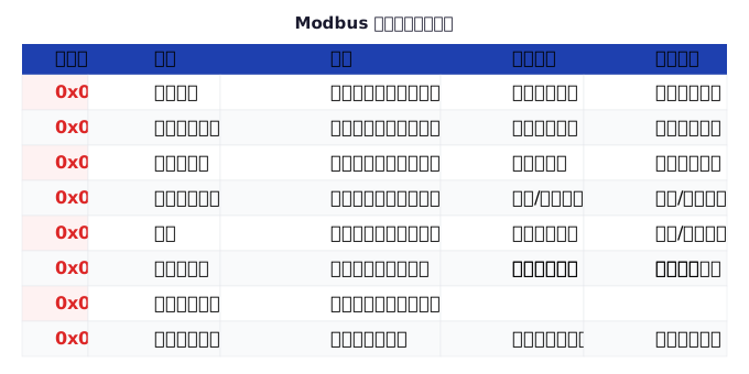
III. Exception Code Quick Reference Table
| Exception Code | Name (English) | Name (Chinese) | Commonality |
|---|---|---|---|
| 0x01 | Illegal Function | Illegal function | ★★★★★ |
| 0x02 | Illegal Data Address | Illegal data address | ★★★★★ |
| 0x03 | Illegal Data Value | Illegal data value | ★★★★☆ |
| 0x04 | Slave Device Failure | Slave device fault | ★★★☆☆ |
| 0x05 | Acknowledge | Confirmation (pending) | ★★★☆☆ |
| 0x06 | Slave Device Busy | Slave device busy | ★★★☆☆ |
| 0x07 | Negative Acknowledge | Negative acknowledgement | ★☆☆☆☆ |
| 0x08 | Memory Parity Error | Memory check error | ★☆☆☆☆ |
| 0x0A | Gateway Path Unavailable | Gateway path unavailable | ★★☆☆☆ |
| 0x0B | Gateway Target Failed | Gateway target response failure | ★★☆☆☆ |
IV. In-depth Fault Diagnosis Methodology
4.1 Layered Troubleshooting Method
Industrial communication fault diagnosis should follow the "bottom-up" principle, starting from the physical layer and gradually moving up to higher layers:
- Physical layer:Check cable connections, terminal resistance, equipment power supply, and grounding conditions
- Data link layer:Use an oscilloscope or logic analyzer to check RS-485 signal quality
- Network layer:In the Modbus TCP scenario, use Wireshark packet capture analysis to
- Application layer:Use tools such as Modbus Poll to send minimal requests to locate the problem
4.2 Comparison and elimination method
When there are multiple devices of the same model on site, using the comparison and elimination method is the most efficient means of locating the problem:
- Swap the suspected faulty device with a normally functioning device
- Use the same master station tool to test both devices separately
- Compare the differences in the response messages of the two devices
4.3 Minimal reproduction method
Simplify complex requests to the simplest legal requests and gradually increase complexity:
步骤 1: 发送最简请求 01 03 00 00 00 01 [CRC] —— 读取地址 0 的 1 个寄存器
步骤 2: 如果成功,逐步增加寄存器数量 00 02, 00 03 ...
步骤 3: 如果失败,缩小地址范围排查
V. Abnormal differences between RTU and TCP modes
Although the definition of abnormal codes is completely consistent in RTU and TCP modes, the abnormal handling processes in the two modes are different:
| Comparison dimension | Modbus RTU | Modbus TCP |
|---|---|---|
| Timeout handling | 3.5 Character time no response timeout determination | TCP connection timeout controlled by the operating system |
| Anomaly detection | CRC check error directly discards the message | TCP layer ensures data integrity |
| MBAP header | None | Requires checking transaction identifier matching |
| Gateway scenario | Less involved | Anomaly codes 0x0A/0x0B are more common |
VI. Programming Implementation: Best Practices for Exception Handling
Below is a complete example of implementing Modbus exception handling in C language, suitable for embedded system development:
/**
 * Modbus 异常码处理函数
 * @param func      请求功能码
 * @param exception 异常码
 * @return 人类可读的错误描述字符串
 */
const char* modbus_exception_str(uint8_t func, uint8_t exception) {
    static char buf[128];
    const char* exc_name;

    switch (exception) {
        case 0x01: exc_name = "非法功能码"; break;
        case 0x02: exc_name = "非法数据地址"; break;
        case 0x03: exc_name = "非法数据值"; break;
        case 0x04: exc_name = "从站设备故障"; break;
        case 0x05: exc_name = "确认(等待中)"; break;
        case 0x06: exc_name = "从站设备忙"; break;
        case 0x07: exc_name = "否定确认"; break;
        case 0x08: exc_name = "存储器校验错误"; break;
        case 0x0A: exc_name = "网关路径不可用"; break;
        case 0x0B: exc_name = "网关目标响应失败"; break;
        default:   exc_name = "未知异常码"; break;
    }

    snprintf(buf, sizeof(buf),
             "Modbus 异常: 功能码 0x%02X → 异常码 0x%02X (%s)",
             func, exception, exc_name);
    return buf;
}

/**
 * 处理 Modbus 响应
 * 返回 0 表示正常响应,负值表示异常
 */
int modbus_handle_response(uint8_t* rsp, int rsp_len,
                           uint8_t expected_func) {
    if (rsp_len < 2) return -1; // 响应长度异常

    uint8_t func = rsp[1]; // RTU 模式下,第二个字节是功能码

    if (func & 0x80) {
        // 异常响应
        uint8_t exception = rsp[2];
        log_error(modbus_exception_str(func & 0x7F, exception));

        // 根据异常码采取不同的重试策略
        switch (exception) {
            case 0x01: // 功能码不支持 - 不重试
            case 0x02: // 地址非法 - 不重试
                return -exception;
            case 0x05: // 确认 - 等待后重试
            case 0x06: // 设备忙 - 延迟重试
                return -exception; // 调用者处理重试逻辑
            default:
                return -exception;
        }
    }

    // 正常响应处理...
    return 0;
}
VII. Frequently Asked Questions (FAQ)
Q1: The Modbus slave returns an exception code 0x02, but the address seems to be correct. Why?
The most common reason is the "address offset 1" issue. Some devices (especially PLCs) have a 1-offset between their Modbus address and protocol address. For example, if the PLC end is configured with an address of 40001, the corresponding internal address in the Modbus protocol is 0 (not 1). Please refer to the device manual to confirm the address mapping relationship.
Q2: Why does the slave sometimes return normal data and sometimes return an exception code 0x06?
This usually means that the CPU processing capability of the slave is insufficient. When the polling frequency is too high, the slave cannot process all requests in time and will return 0x06. Solution: Reduce the polling frequency, or reduce the number of registers in a single request.
Q3: What is the difference between exception codes 0x05 and 0x06?
0x05 (Acknowledged): The slave is already processing the specific request you sent and needs to wait for it to complete. 0x06 (Device Busy): The slave is currently unable to process any new requests, possibly due to any operation. Simple memory: 0x05 means "I'm working on your request", and 0x06 means "I'm busy right now, don't come to me".
Q4: If the slave does not respond at all (timeout) instead of returning an exception code, how should I troubleshoot?
Complete lack of response usually means that the problem lies in the physical layer or data link layer:
- Check whether the slave address is correct (address mismatch is the most common reason for the slave to be silent)
- Check if the A/B wires of RS-485 are reversed
- Check if the baud rate and parity mode match
- Check the terminating resistor and bias resistor
- Use an oscilloscope to confirm whether there is a signal on the bus
VIII. Summary
The abnormal response mechanism of Modbus is a highlight in protocol design - it does not simply let the communication fail, but precisely informs the master station of "what went wrong" through abnormal codes. Mastering the meaning and troubleshooting methods of these abnormal codes can shorten the fault localization time from hours to minutes.
It is recommended to print out the quick reference table of abnormal codes in this article and post it next to the workstation, or integrate automatic parsing functionality for abnormal codes into the debugging tool. In the industrial field, every minute of downtime means real financial losses - and quickly locating Modbus abnormal codes is often the first step towards solving the problem.
Related reading:Complete Analysis of Modbus Function Codes | Deep Comparison between Modbus RTU and TCP | Modbus CRC Check Principle and Programming Implementation


Leave a Reply