
Abstract: This paper introduces a method for implementing network communication between AB PLC and M0DBUS using the 3100/3150-MCM module. This method employs the M0DBUS protocol and involves developing an application for AB PLC, thereby achieving master-slave network communication.
I. Introduction
Currently, PLCs and various intelligent instruments are widely used in industrial control sites for production process control. As the scale of control expands and control functions become more complex, multiple PLCs and a certain number of peripheral instruments are often required to form a control system.
M0DBUS is a serial transmission protocol developed by M0DIC0N, USA, enabling master-slave command-response communication. As an industrial communication and distributed control system protocol, it has been supported by PLCs and intelligent instruments from multiple companies.
A-B Company (Allen-Bradley) is one of the major manufacturers of programmable controllers in the United States, with advanced communication and data processing capabilities. In the water treatment industry, a large number of programmable controllers are used for production process control, with A-B Company's PLCs accounting for a significant proportion.
Due to different hardware vendors supporting different industrial communication and distributed control system protocols, there exists a problem of protocol conversion when implementing a control network composed of AB PLCs and M0DBUS instruments to achieve device networking.
The 3100/3150-MCM module is an M0DBUS communication interface module launched by PR0s0FT TECHN0L0GY, installed on the universal framework of AB PLCs. This module enables communication between AB PLCs and M0DBUS field devices, thereby enhancing the communication capabilities of AB PLCs, flexibly achieving interconnection between AB PLCs and M0DBUS networks, and fulfilling complex control requirements.
Based on the design of a distributed control system for a waterworks pump station, this paper focuses on the implementation method of connecting AB Company's sLC series PLCs through the 3150-MCM module and M0DBUs network.
II
The distributed control system of the waterworks pump station not only implements general logic control but also possesses functions such as numerical processing, including analog quantity processing, and network communication. In practical on-site applications, the motor protection device sepam2000 used in the system adopts the M0DBUS communication protocol. Due to the requirements of system control functions, support for the M0DBUS protocol in AB PLC is necessary. We utilize the 3150-MCM module to establish an M0DBUS device network.
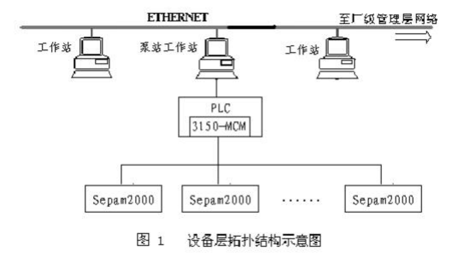
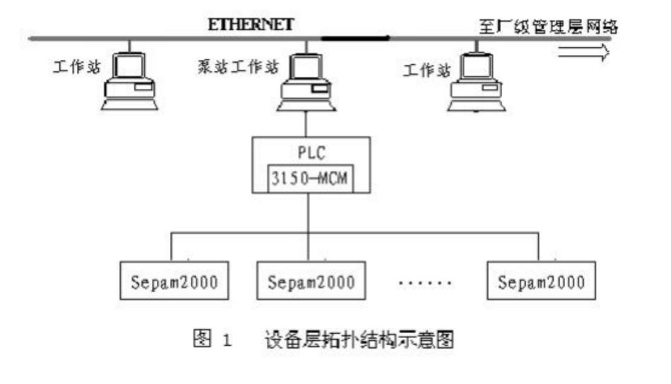
The network structure of the system follows the specifications of the M0DBUS protocol, adopting a standard and simple master-slave bus structure. The PLC serves as the master to initiate communication, with multiple motor protection devices sepam2000 acting as slaves. Each slave must wait for a permission signal from the master before proceeding with transmission. The master can send and receive information from slaves on the communication link, while the slaves are always in a passive state, ready to respond to communication requests from the master at any time
The network structure of the device layer is shown in Figure 1.
III. Introduction to sepam2000 and M0DBUs Protocols
sepam2000, as a motor protection device, provides all functions including protection, measurement, control, and communication.
The communication between sepam2000 and the remote monitoring system adopts the M0DBUs protocol.
The M0DBUs communication adopts a master/slave data transmission mode. In this master-slave communication structure, there is one master and multiple slaves. The master can communicate bidirectionally with each slave, while slaves cannot communicate with each other. The message format for communication between the master and each slave is in the form of request/response frames. Each communication is initiated by the master without handshake. After sending a request frame, the master waits for the slave to return a response frame until the response time expires. The slave can only respond to the master's request by providing data or taking corresponding actions based on the request.
The M0DBUs protocol defines the format of the master's request, including addressing, function code for required actions, transmission data, and error checking. The addressing (i.e., address code) in the request provides the address of the slave receiving the master's message. The slave determines whether to accept the request based on the address. Users must set the address for each slave. The function code instructs the specified slave to perform a certain action. The data field contains additional information required for the slave to execute the task. For example, function code 03 indicates to read the slave's hold register and return its content. The information in the data area must tell the slave which register to start reading from and the number of registers to read. The error checking field provides a method for the slave to verify the integrity of the information. Similarly, the response format also follows the M0DBUs protocol structure. The function code of the slave's response corresponds to the function code of the accepted request. The data field contains the data returned according to the request, and the error checking field allows the master to confirm whether the information content is valid.
The M0DBUs protocol has a total of 24 functional codes, but not all of them are applicable to sepam2000. In practical applications, sepam2000 only supports a limited number of the following:
01 Read output status
02 Read input status
03 Read the contents of internal registers
04 Read the contents of the input register
05 Force single output state
06 Refresh the content of a single register
07 Read Exception Event Status
08 Diagnostic Test
11 Read Counter and Status Word
15 Force Multiple Output States
16 Refresh Multiple Register Contents
If the host wishes to read the contents of registers 0805h-080Ah in the No. 2 sepam2000 slave, it needs to call function 03. The frame formats for host requests and slave responses are as follows:
Request Frame:
| Address | Function Number | Data Starting Register Addressing | Register Count | Error Check Field |
| 2 | 03 | 0C05 | 06 | CRC16 |
Response Frame:
| Address | Function Number | Byte Count | Data Register (0805) | ... | Data Register (080A) | Error Check Field |
| 2 | 03 | 0C | Data1 | …… | Data6 | CRC16 |
If the host wishes to refresh the content of register 0810h in the sepam2000 slave device number 2 and set the register content to 1000, it needs to call function 06. The frame formats for the host request and slave response are as follows:
Request frame:
| Address | Function number | Register addressing | Set value | Error check field |
| 2 | 06 | 0C0E | 1000 | CRC16 |
Response Frame: (Return the received request frame)
| Address | Function Number | Register Addressing | Set Value | Error Check Field |
| 2 | 06 | 0C0E | 1000 | CRC16 |
The frame format and the functions executed by sepam2000 are clearly defined and cannot be changed arbitrarily. During communication, it is necessary to ensure the correct correspondence between the host and each slave device. In addition, users can configure appropriate communication parameters such as transmission baud rate, character parity, and the number of stop bits according to actual needs.
IV. Implementation of M0DBUs Protocol in AB PLC
1. Communication Control of MCM Module
The 3100/3150-MCM communication module from PR0s0FT TECHN0L0GY is equivalent to a network interface, and the PLC is connected to the M0DBUs bus through the MCM module. The MCM module can quickly and reliably implement the M0DBUs protocol in AB PLC.
The 3100/3150-MCM communication module allows users to choose between master mode and slave mode. When the MCM module is set as the master, it controls the slaves connected to the bus, supports 8 function codes in the M0DBUs protocol (01, 02, 03, 04, 05, 06, 15, 16), can send up to one hundred customized request commands, and supports sending requests in a "broadcast" manner. When the MCM module is designated as a slave, it responds to the master's requests and supports 9 function codes in the M0DBUs protocol (01, 02, 03, 04, 05, 06, 08, 15, 16). Meanwhile, whether in master mode or slave mode, the 3100/3150-MCM communication module supports both ASCII and RTU transmission modes.
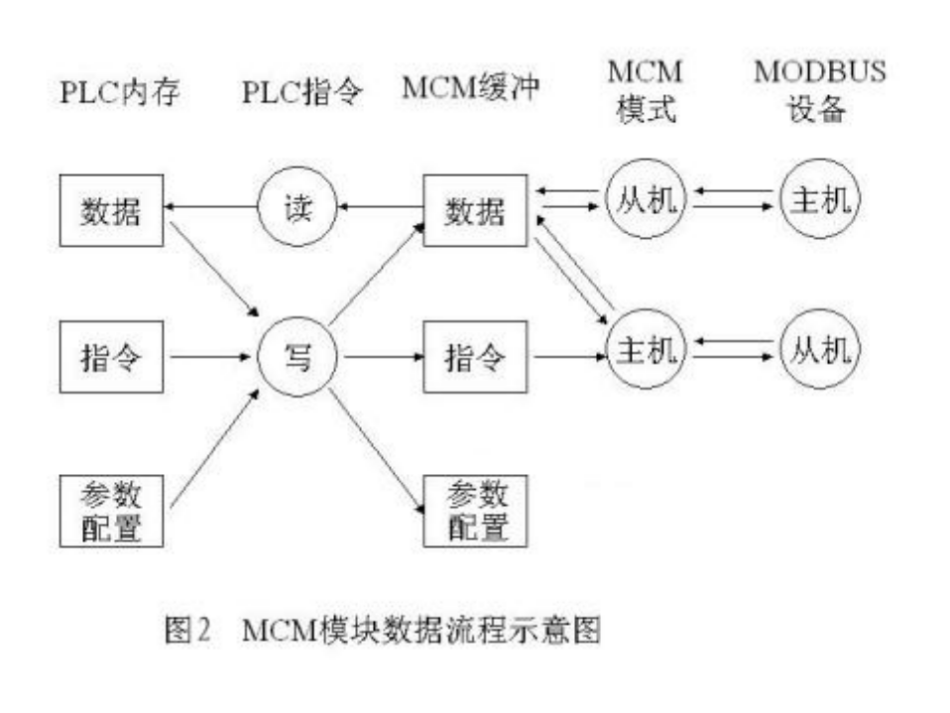
When the AB PLC is configured with the 3100/3150-MCM communication module in master mode, the PLC adopts a periodic scanning method to exchange data with the slaves in the order of request commands. During each scan, the processor uses logical write instructions to transfer the data to be output to each slave from the master's memory to the send buffer of the 3100/3150-MCM communication module, and the module sends it to the designated slave according to the stored function instructions. The data returned by each slave after response is first stored in the receive buffer of the 3100/3150-MCM communication module, and then the PLC uses logical read instructions to move the data into the corresponding input data storage area. This cycle repeats, enabling periodic refreshing of data between the master and slaves. The entire data flow is shown in Figure 2:
2. Hardware Connection between MCM Module and M0DBUs
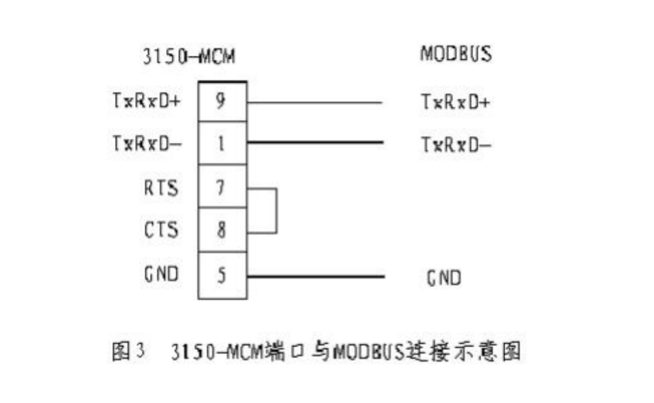
The MCM module uses a standard communication interface compatible with RS232C, but in practical applications, due to the need to implement multi-point communication, RS485 is used.
3. Buffer management of MCM module
Data is transmitted between the PLC and MCM modules through module input and output mapping files. When the PLC writes data, it writes the data into the output mapping file, and then the 3100/3150-MCM communication module maps the data to the corresponding buffer location. When the PLC reads data, it reads the data from the input mapping file at the corresponding address in the module buffer based on the mapped address. The data transmission unit of the mapping file is a 50-byte data block, and the PLC must transmit one data block at a time in a cyclic manner.
MCM divides the buffer into several blocks based on the unit size of data transmission, assigns numbers to each block, and maps them with block numbers. It is also divided into three areas, which are used for data, instructions, and parameter settings respectively. The data storage area starts from block number 0 and ends at block number 79, with a space of 4000 bytes in between, used to store received and sent data. It is the place where the host and the slave exchange data. The instruction storage area spans from block 80 to block 99, with a total of 1000 bytes, used to store the function instruction table of the module in host mode. During each scan, a request frame is sent to the slave according to the function instruction list in order. The first 40 bytes of block number 255 are specifically defined as the module setting parameter storage area, used for initializing the module.
During the communication process, the host must first be initialized, which involves configuring the parameters of the buffer content corresponding to block number 255. This mainly involves defining the settings of the communication port and the detailed division of the module buffer. The following parameters are set:
(1) Define two independent communication interface settings for the MCM communication module. This includes selecting the master or slave mode, defining the character parity, the number of stop bits, the baud rate for transmission, response delay, and other parameters.
(2) Define the data storage area for storing received data in the buffer of the module. This includes: the starting block number of the received data storage area, and the number of consecutive blocks in the storage area.
(3) Define the data storage area for storing the sending data in the buffer of the module. This includes: the starting block number of the sending data storage area, and the number of consecutive blocks in the storage area.
(4) Define the instruction storage area in the buffer of the module. Since the instruction storage area starts from data block number 80, it is only necessary to specify the block number of the storage area.
4. Function instruction setting of MCM module
When the MCM module is in host mode, the list of function instructions is stored in the instruction storage area of the module buffer. When the host sends a request to the slave, the module reads out the function instructions one by one from the instruction storage area and sends data in the format of M0DBUs request frames.
The specific content of each function instruction in the instruction storage area is as follows:
| 1 | Module communication port selection |
| 2 | Slave station address. The slave compares the value of its own station address with the received station address when receiving data, to determine whether the information is intended for its own station. The host, on the other hand, compares the received station address with the sent station address to determine whether it is a correct response from the slave |
| 3 | Function encoding of the instruction |
| 4 | Source address. This is the starting data address of the data to be sent or received by the host in the buffer |
| 5 | Data length. This is the number of bytes of the data to be sent or received by the host |
| 6 | Destination address. This is the register address of the data to be received or responded to by the slave |
| 7 | Data type. This indicates whether the read or write data is a double-byte floating-point number or a single-byte integer |
| 8 | Polling time |
If the host wishes to read the contents of registers 0805h-080Ah in the sepam2000 slave device number 2 from communication interface number 1 and store them in the continuous 6 bytes starting from the 50th byte of the module buffer,
The content of the function instruction is as follows:
| Port number | Slave address | Function code | Source address | Data length | Destination address | Type | Time |
| 1 | 2 | 3 | 50 | 6 | 0805 | 0 | 0 |
5. Development of AB PLC communication program
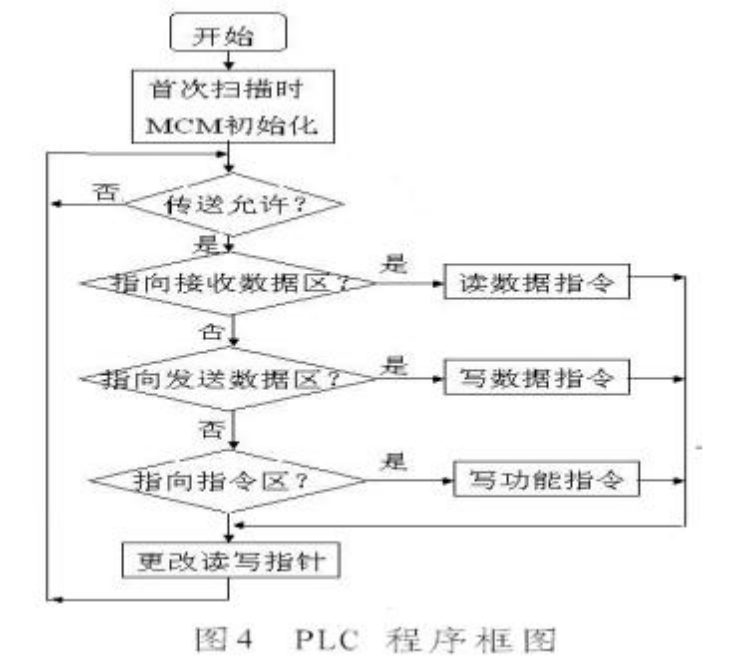
During the first scanning cycle when the program is executed, the status of the MCM must be set, that is, the MCM module must be initialized.
In the communication program, the PLC sets the current and subsequent read/write pointers for the MCM buffer in the input and output mapping files, pointing to the current MCM buffer data block number and the subsequent buffer data block number, respectively. If the MCM is in a data transfer enabled state, that is, I1:1/0 = 1 and 00:1/0 = 0, the PLC judges the current read/write pointer and calls the corresponding read/write logic instruction. If the pointer points to the data storage area for receiving data, the PLC receives data from the MCM module; if the pointer points to the data storage area for sending data, the PLC sends data to the MCM module; if the pointer points to the instruction storage area, the PLC transmits the function instruction to the MCM module. Each time a data block is transferred, and after the transfer, the subsequent read/write pointer overwrites the current read/write pointer, so that the next data block can be transferred in the next scanning cycle. The PLC automatically scans periodically and sends/receives data to/from the slave's input/output data according to the programmed function instructions, to meet the requirements of data transmission.
Based on the logic instructions of PLC and the communication principles of MCM, a structural block diagram of the host communication program
shown in Figure 4 was drawn.
V. Conclusion
After on-site debugging, a M0DBUs network connection consisting of one AB PLC and 13 sEPAM2000 devices was achieved. Practical application has proven that the system structure composed in this way is simple, easy to apply, and capable of meeting complex control needs.


Leave a Reply