
Description
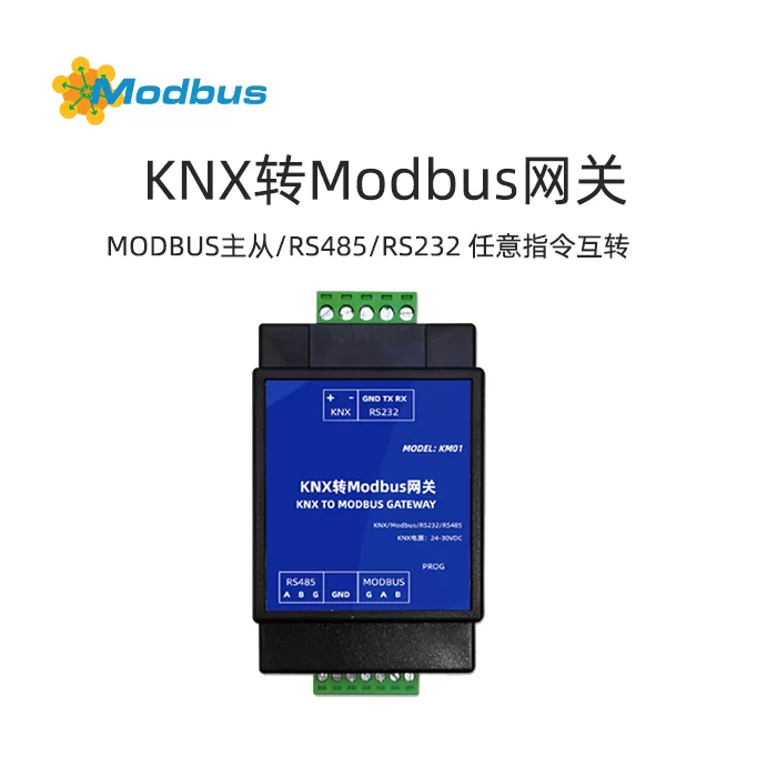
Function Description:A module that supports KNX<->MODBUS master-slave/RS485/RS232 arbitrary instructions (up to 24 bytes) to be converted to each otherSelection Recommendation:Widely applicable to users with IoT centralized control and monitoring needs, such as smart buildings, smart agriculture, smart exhibition halls, office building energy management, smart banking management, smart hospitals, IoT schools, airport management, museum exhibitions, and dynamic environment monitoring in computer rooms. It is also suitable for professionals such as weak current integrators and building integrators.Product features:1. ETS configuration interface.
Modbus usage method
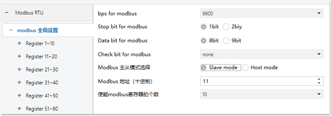
Modbus communication parameter configuration① Bps for modbus:Set communication baud rate, supporting 2400, 9600, 19200, 38400, 56000, 115200, 128000, 256000. ② Modbus master-slave mode selection:Slave mode: Slave mode, Host mode: Host mode.③ Modbus Address (Decimal):The address setting of the local machine in Modbus slave mode.④ (Host Only) Read/Write Timeout in Host Mode (* 100ms):In host mode, when reading slave devices, the timeout time for waiting for a response from the slave is set. Setting 5 represents 500ms, and the minimum cannot be less than 200ms. It is recommended to be above 500ms, and the default is 500ms.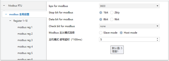
 Modbus Register Configuration
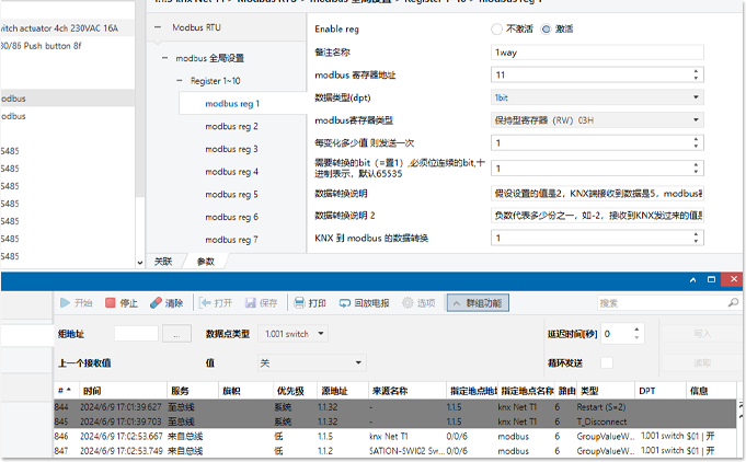
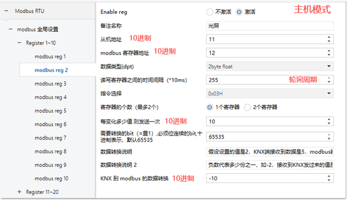
① Configuration Notes:Register addresses should be configured in ascending order as much as possible. In host mode, all registers of the same device are placed together and arranged in ascending order (such as registers 1-10 of slave 1, corresponding to modbus reg 1~modbus reg10 configured by the gateway). This configuration allows the gateway to read slave registers when reading them. It can be read in one go without having to read each register individually, greatly improving efficiency.② Enable reg:Activated means enabled, inactive means not enabled.③ Note Name:You can label what the register corresponds to according to your needs.④ Slave address (host only):Set the address (in decimal) of the slave machine that needs to be read.⑤ Modbus register address:10 base.⑥ Data type (dpt):The data type of KNX object.⑦ Modbus register type:The hold register modbus host can read and write, the input register modbus host can only read, and the coil state modbus host can read and write.⑧ Time interval (host only):The time interval for reading each register in host mode is set to 0 by default.⑨ Instruction selection (host only):The instruction selection for reading registers is 0X03H/0X04H/0X06H/0X10H/0X01H/0X02H/0X05H/0X0FH⑩ Number of registers (host only):You can choose to read both registers 1 and 2 together, merge them, and forward them to KNX.①① Data format (host only):You can choose the high byte first and high byte second modes, and set them according to the specific data format.①② Send once for every value change:Set 0 to forward regardless of the change, set 1 to forward when the value changes by 1 (suitable for switch values), and set 10 to forward when the current value changes by ≥ 10.①③ The bits that need to be converted:refers to the values of which bits in the register are taken and forwarded to KNX. Similarly, when KNX is transferred to the Modbus register, the values of the other bits remain unchanged. As shown in the figure below, 1 is set to represent hexadecimal 0x0001, which forwards the lowest bit data. If the value of the register is 0x1231, KNX forwards 1. If the value of the register is 0x1230, KNX forwards 0. The default value is 65535, which is 0xFFFF, forwarding all 16 bit values.①④ KNX to Modbus Data Conversion:This is a multiple used to process data conversion. For example, assuming the set value is 2, KNX receives 5 data, and Modbus registers receive 10 data; A negative number represents one part, such as -2. If the value received from KNX is 10, then the data in the Modbus register is 5. In application scenarios such as temperature conversion, most temperature values in Modbus are accurate to one decimal place, but KNX is accurate to two decimal places, so there is a difference of 10 times between them. You can set -10 to correct the temperature value. The default value is 1, and the original data is forwarded.
Modbus Register Configuration
① Configuration Notes:Register addresses should be configured in ascending order as much as possible. In host mode, all registers of the same device are placed together and arranged in ascending order (such as registers 1-10 of slave 1, corresponding to modbus reg 1~modbus reg10 configured by the gateway). This configuration allows the gateway to read slave registers when reading them. It can be read in one go without having to read each register individually, greatly improving efficiency.② Enable reg:Activated means enabled, inactive means not enabled.③ Note Name:You can label what the register corresponds to according to your needs.④ Slave address (host only):Set the address (in decimal) of the slave machine that needs to be read.⑤ Modbus register address:10 base.⑥ Data type (dpt):The data type of KNX object.⑦ Modbus register type:The hold register modbus host can read and write, the input register modbus host can only read, and the coil state modbus host can read and write.⑧ Time interval (host only):The time interval for reading each register in host mode is set to 0 by default.⑨ Instruction selection (host only):The instruction selection for reading registers is 0X03H/0X04H/0X06H/0X10H/0X01H/0X02H/0X05H/0X0FH⑩ Number of registers (host only):You can choose to read both registers 1 and 2 together, merge them, and forward them to KNX.①① Data format (host only):You can choose the high byte first and high byte second modes, and set them according to the specific data format.①② Send once for every value change:Set 0 to forward regardless of the change, set 1 to forward when the value changes by 1 (suitable for switch values), and set 10 to forward when the current value changes by ≥ 10.①③ The bits that need to be converted:refers to the values of which bits in the register are taken and forwarded to KNX. Similarly, when KNX is transferred to the Modbus register, the values of the other bits remain unchanged. As shown in the figure below, 1 is set to represent hexadecimal 0x0001, which forwards the lowest bit data. If the value of the register is 0x1231, KNX forwards 1. If the value of the register is 0x1230, KNX forwards 0. The default value is 65535, which is 0xFFFF, forwarding all 16 bit values.①④ KNX to Modbus Data Conversion:This is a multiple used to process data conversion. For example, assuming the set value is 2, KNX receives 5 data, and Modbus registers receive 10 data; A negative number represents one part, such as -2. If the value received from KNX is 10, then the data in the Modbus register is 5. In application scenarios such as temperature conversion, most temperature values in Modbus are accurate to one decimal place, but KNX is accurate to two decimal places, so there is a difference of 10 times between them. You can set -10 to correct the temperature value. The default value is 1, and the original data is forwarded.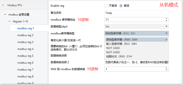
RS485 Usage
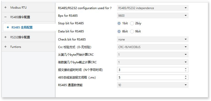
RS485 Communication Parameter Settings① Bps for Modbus:Set the baud rate of the RS485 bus.② Stop bit for RS485:Stop bit setting, only supports 1-bit and 2-bit.③ Data bit for RS485:Data bit setting, only supports 8-bit and 9-bit.④ Check bit for RS485:Check bit setting, only supports odd check and even check or no check.⑤ Crc check (0-no check):provides a multi criteria CRC check algorithm and offers length selection for selecting CRC check source data.⑥ Calculate CRC from the nth BYTE:Set the starting position of CRC.⑦ What is the last BYTE deadline for settlement CRC:Set the end position of CRC.⑧ Message reception timeout time (N character time):The time when the RS485 bus recognizes the end of a frame, one character time * N.⑨ RS485 bus sends message interval (. ms):The minimum time interval for this device to send a frame of message to the bus.⑩ RS485 Channel Number Enable
 RS485 Instruction Configuration
① Remarks Name:You can label what this instruction corresponds to according to your needs.② Data format of KNX (dpt):Data type of KNX object.③ Does KNX send the message to RS485 after receiving it.
④ Whether RS485 forwards the message to KNX after receiving it.
⑤ Forwarding method:After receiving the correct instruction from the RS485 bus, select the value to forward to KNX. Forward the received value, then forward the data at the position replaced by XX in the instruction; Forward fixed values and send the set values on KNX.⑥ Data forwarding settings:Refer to the seventh point of Modbus register configuration.⑦ Instruction Content:The instruction is input in hexadecimal format, separated by spaces between eachbyte, and uses the letter XX to represent the data that needs to be converted to KNX. All instruction contents are not case sensitive.
RS485 Instruction Configuration
① Remarks Name:You can label what this instruction corresponds to according to your needs.② Data format of KNX (dpt):Data type of KNX object.③ Does KNX send the message to RS485 after receiving it.
④ Whether RS485 forwards the message to KNX after receiving it.
⑤ Forwarding method:After receiving the correct instruction from the RS485 bus, select the value to forward to KNX. Forward the received value, then forward the data at the position replaced by XX in the instruction; Forward fixed values and send the set values on KNX.⑥ Data forwarding settings:Refer to the seventh point of Modbus register configuration.⑦ Instruction Content:The instruction is input in hexadecimal format, separated by spaces between eachbyte, and uses the letter XX to represent the data that needs to be converted to KNX. All instruction contents are not case sensitive.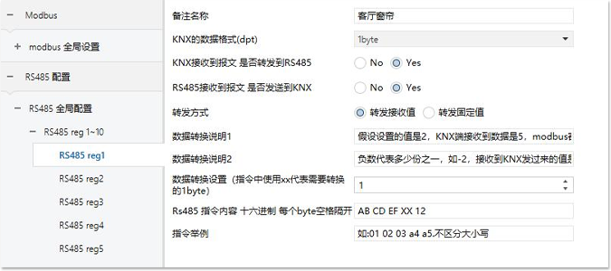
RS232 usage method
RS232 configuration is the same as RS485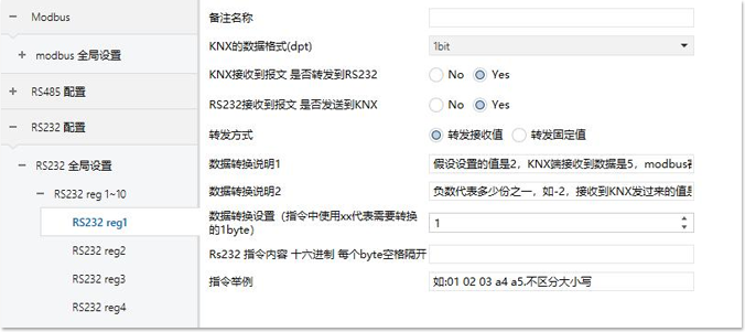
Function configuration
Global configuration① Number of channels: Maximum of 100.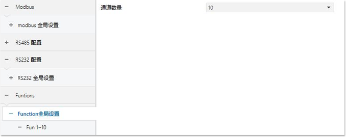 Fun parameter configuration
① enables the current function function.
② Function selection:Delay function provides delayed sending function, 2-point logic function provides simple 2-point control logic (triggering one operation above set point A and another operation below set point B).③ Object dpt:Configure the required data type.④ (Delay) Delay (seconds):0 represents no delay, 0~255.⑤ (Delay) Delay (milliseconds):0 represents no delay, 0-255.⑥ (2-point) High threshold setting:When the input value is higher than the set value, after a delay of the set time, send the value parameter set when it is higher than the high threshold.⑦ (2-point) Low threshold setting:When the input value is higher than the set value, after a delay of the set time, send the value parameter set when it is lower than the low threshold.⑧ (2-point) Out. Object dpt:Control the data format of the output object:⑨ (2-point) Send value when it is higher than the high threshold:
⑩ (2-point) Send value when it is lower than the low threshold:
①① (2-point) Delay time (. min):Set the delay output time in minutes.①② (2-point) Delay time (. sec):Set the delay output time in seconds.①③ Note:When the input value is higher than the high threshold and a value lower than the high threshold is received again within the delay time, the transmission will be canceled. The function remains the same when it is below the low threshold.
Fun parameter configuration
① enables the current function function.
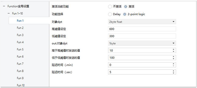
② Function selection:Delay function provides delayed sending function, 2-point logic function provides simple 2-point control logic (triggering one operation above set point A and another operation below set point B).③ Object dpt:Configure the required data type.④ (Delay) Delay (seconds):0 represents no delay, 0~255.⑤ (Delay) Delay (milliseconds):0 represents no delay, 0-255.⑥ (2-point) High threshold setting:When the input value is higher than the set value, after a delay of the set time, send the value parameter set when it is higher than the high threshold.⑦ (2-point) Low threshold setting:When the input value is higher than the set value, after a delay of the set time, send the value parameter set when it is lower than the low threshold.⑧ (2-point) Out. Object dpt:Control the data format of the output object:⑨ (2-point) Send value when it is higher than the high threshold:
⑩ (2-point) Send value when it is lower than the low threshold:
①① (2-point) Delay time (. min):Set the delay output time in minutes.①② (2-point) Delay time (. sec):Set the delay output time in seconds.①③ Note:When the input value is higher than the high threshold and a value lower than the high threshold is received again within the delay time, the transmission will be canceled. The function remains the same when it is below the low threshold.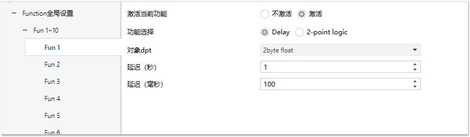
Example Tutorial
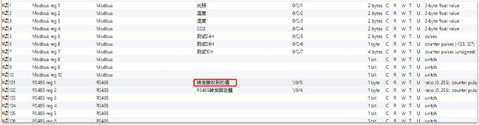
RS485/RS232 to KNX① Forwarding Fixed Values: Set the group address of RS485/RS232 channel 2 to 1/0/4, set the hexadecimal instruction of channel 2 to 0x12345678, and when the converter receives the message sent by RS485/RS232 as 0x12345678, it sends a value of 50 to the KNX end group address 1/0/4.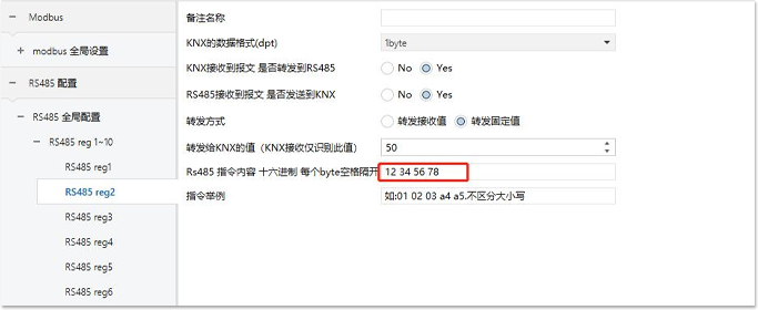
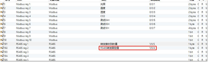
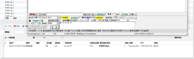
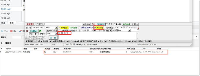 ② can also be one of the values for forwarding received instructions: use xx to represent the value that needs to be forwarded. When the group address of channel 1 is set to 1/0/5 and the instruction content of channel 1 is set to 0Xabcdefxx12, and the converter receives the message 0xabcdef0812 sent by RS485/RS232, the KNX end will forward the 08 at xx position to the corresponding address 1/0/5.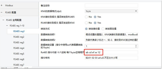
 MODBUS to KNX① Set Modbus to slave mode, set the group address of Modbus channel 1 to 0/0/6, set the data type to 1 bit (consistent with KNX relay), and also set the group address of KNX relay to 0/0/6. When the lowest bit of the corresponding register 11 value is 0, the corresponding KNX relay is turned off. When the lowest bit is 1, the KNX relay is turned on.