
Product Overview
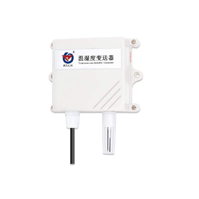
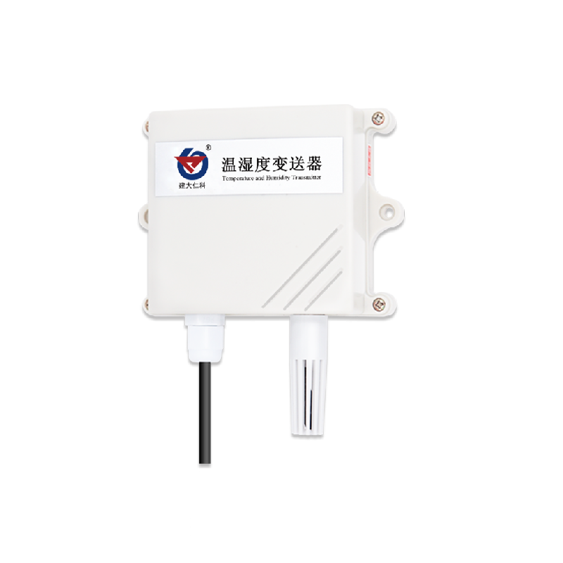
This product is a wall mounted high protection level shell, Protection Rating Rain and snow resistant with good breathability IP65, The circuit adopts industrial grade microprocessor chips imported from the United States. Imported high-precision temperature sensor, Ensure excellent reliability of the product, High precision and interchangeability, This product uses a particle sintered probe sheath.
The probe is directly connected to the housing and has a beautiful and elegant appearance, The output signal type is. The farthest communication possibleRS485, Rice 2000 Standard, agreement modbus Support secondary development, Functional characteristics.
Adopting measurement units imported from Switzerland
Accurate measurement, Adopt specialized. Circuit 485 Communication stability, Wide voltage range power supply. 10~30V Complete specifications, Easy installation, Main technical parameters.
DC power supply
Default (Maximum power consumption) : DC 10-30V
Precision accuracy: 0.1W (DC24V)
A Humidity : Temperature ±2%RH(60%RH,25℃) , Precision accuracy ±0.4℃ (25℃)
B Default (Humidity) : Temperature ±3%RH(60%RH,25℃), Transmitter circuit ±0.5℃ (25℃)
Working temperature and humidity: Non condensing -40℃~+60℃, 0%RH~95%RH (Probe operating temperature)
Default: -40℃~+120℃ Probe working humidity: -40℃~+80℃
Temperature display resolution: 0%RH-100%RH
Humidity display resolution: 0.1℃
Temperature and humidity refresh time: 0.1%RH
Long term stability: 1s
Humidity:
Temperature ≤1%RH/y
Response time ≤0.1℃/y
Humidity : Wind speed ≤8s(1m/s Temperature), Wind speed ≤25s(1m/s Output signal)
agreement: RS485(Modbus Installation method)
Wall mounted: Wiring instructions
Wide voltage power input
Both are acceptable 10~30V Attention should be paid when wiring signal lines. 485 Attention should be paid when wiring signal lines AB Two lines cannot be connected in reverse, More on the bus
The addresses between devices cannot conflict.
Communication protocol
| code | 8 Bit binary |
| Data bits | 8 Position |
| Parity check bit | None |
| Stop position | 1 Position |
| Error verification | CRC (Redundant cyclic code) |
| Baud rate | 2400bit/s, 4800bit/s, 9600bit/s Can be set up, The factory default is 4800bit/s |
useModbus-RTU Communication protocol, The format is as follows::
Initial structure ≥4 Byte time
Address code = 1 Byte
Function code = 1 Byte
Data area = N Byte
Error verification = 16 PositionCRC Code
End the structure ≥4 Byte time
Address code: Provide the address of the transmitter, It is unique in communication networks (Factory default0x01) .
Function code: Function indication of instructions issued by the host, This transmitter supports function codes0x03 (Read register data) , 0x06 (Write register data) .
Data area: The data area is specific communication data, Note High byte data comes first16bitsCode!
CRCTwo byte checksum: Host query frame structure.
Address code
| Function code | Register starting address | Register length | Low bit of verification code | High bit of verification code | Byte |
| 1 Byte | 1 Byte | 2 Byte | 2 byte | 1 byte | 1 Byte |
Slave response frame structure
| Address code | Function code | Effective byte count | Data Zone 1 | Second data area | The N Data area | Verification code |
| 1 Byte | 1 Byte | 1 Byte | 2 Byte | 2 Byte | 2 Byte | 2 Byte |
Register address
| Register address | PLCOr configure the address | Content | Operation | explain |
| 0000 H | 40001 | Humidity | Read only | Real time humidity value (expand10Double |
| 0001 H | 40002 | Temperature | Read only | Real time temperature value (expand10Double) |
| 0050H | 40081 | Temperature calibration value | Read and write | Integer (expand10Double) |
| 0051H | 40082 | Humidity calibration value | Read and write | Integer (expand10Double) |
| 07D0 H | 42001 | Equipment address | Read and write | 1~254 (Factory default1) |
| 07D1 H | 42002 | Baud rate | Read and write | 0Representative2400 1Representative4800 2Representative9600 |
Examples and explanations of communication protocols
give an example: Read device address 0x01 Temperature and humidity values, Change address
Inquiry frame (16 Base system) :
| Address code | function code | Starting address | Data length | Low bit of verification code | High bit of verification code |
| 0x01 | 0x03 | 0x00 0x00 | 0x00 0x02 | 0xC4 | 0x0B |
Response frame (16 Base system) : (For example, reading the temperature as-10.1℃, The humidity is 65.8%RH)
| Address code | Function code | Return the number of valid bytes | Humidity value | Temperature value | Low bit of verification code | High bit of verification code |
| 0x01 | 0x03 | 0x04 | 0x02 0x92 | 0xFF 0x9B | 0x5A | 0x3D |
Temperature calculation:
When the temperature is below 0 ℃ Upload temperature data in the form of supplementary codes.
Temperature: FF9B H(hexadecimal)= -101 => Temperature = -10.1℃
Humidity calculation:
Humidity: 292 H (hexadecimal)= 658 => Humidity = 65.8%RH
give an example: Equipment address 0x01 Modify to: 0x02
Inquiry frame (16 Base system) : (Assuming the modified address is 0x02 Note After modifying the address, the device needs to be powered off and restarted: Address code)
| Function code | Starting address | Modify numerical values | Low bit of verification code | High bit of verification code | Response frame |
| 0x01 | 0x06 | 0x07 0xD0 | 0x00 0x02 | 0x08 | 0x86 |
Base system (16 Address code) :
| Function code | Starting address | Modify numerical values | Low bit of verification code | High bit of verification code | Common problems and solutions |
| 0x01 | 0x06 | 0x07 0xD0 | 0x00 0x02 | 0x08 | 0x86 |
The device cannot connect to
Or computer PLC Possible reasons
There are multiple computers:
1)Mouth COM The selected mouth is incorrect, Equipment address error
2)Or devices with duplicate addresses, The factory default is all (Baud rate 1) . 3)Verification method, data bit, data bit, Stop position error. 4)485 The bus is disconnected, Or A, B Reverse wire connection.
5)Too many devices or too long wiring, Power should be supplied locally, Add 485 Enhancer, Simultaneously increase 120ΩTerminal resistance.
6)USB Turn 485 Driver not installed or damaged
7)Equipment damage


Leave a Reply