
1. Introduction to Custom Protocol Instructions
Custom instructions are designed to facilitate users in utilizing other protocols in certain projects, rather than being limited to the TDFH standard protocol, thereby expanding the scope of protocol usage. For instance, the modbus protocol can be utilized in projects. Custom protocols primarily consist of two major modules: one for sending custom protocols and the other for receiving and parsing custom instructions.
2. How to Send Custom Protocols
Create a new or open an existing project file, select a control (here, we take the button control as an example), add an event, and set the processing method as "Command sending → [Custom protocol] send serial port command". You can add a custom protocol for the control to send, as shown in Figure 2.1.
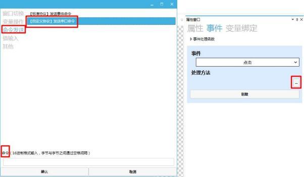 Figure 2.1 Adding Custom Protocol Sending
3. How to Send Custom Protocol Messages
1. Description of Custom Instruction Functions
Click the input box under the command to pop up the window for describing custom instruction functions. You can enter hexadecimal numbers in the input box, perform arithmetic operations, and apply CRC algorithms. Set up custom protocol sending according to the window for describing custom instruction functions, as shown in Figure 3.1.
Figure 2.1 Adding Custom Protocol Sending
3. How to Send Custom Protocol Messages
1. Description of Custom Instruction Functions
Click the input box under the command to pop up the window for describing custom instruction functions. You can enter hexadecimal numbers in the input box, perform arithmetic operations, and apply CRC algorithms. Set up custom protocol sending according to the window for describing custom instruction functions, as shown in Figure 3.1.
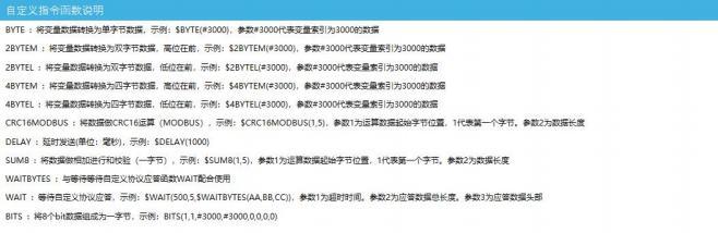 Figure 3.1 Description of Custom Instruction Functions
BYTE
This keyword is a single byte, such as $BYTE(#3000), which means to take the lowest byte of the value of the variable with index 3000 at that position. For example, if the value of the variable with index 3000 is 0x1024, and if you need to send the custom protocol 55 AA $BYTE(#3000) 10 ff, then the custom protocol instruction sent will be:
55 AA 24 10 FF.
You can also perform arithmetic operations: 55 AA $BYTE(#3000+2) 10 ff, then the custom protocol instruction sent will be: 55 AA 26 10 FF.
2BYTEM
has the same usage as BYTE, but this keyword represents two bytes, with the 'M' at the end indicating that the high-order bits come first. For example, if the value of a variable with index 3000 is 0x1234, then the position is represented as 0x12 0x34. Assuming that a custom protocol 55 AA $2BYTEM(#3000) 10 ff needs to be sent, the custom protocol instruction sent would be: 55 AA 12 34 10 FF.
2BYTEL
has the same usage as 2BYTEM, but with the 'L' at the end indicating that the low-order bits come first. For example, if the value of a variable with index 3000 is 0x1234, then the position is represented as 0x34 0x12. Assuming that a custom protocol 55 AA $2BYTEL(#3000) 10 ff needs to be sent, the custom protocol instruction sent would be: 55 AA 34 12 10 FF.
4BYTEM
has the same usage as BYTE, but this keyword represents four bytes, with the 'M' at the end indicating that the high-order bits come first. For example, if the value of a variable with index 3000 is 0x12345678, then the position is represented as 0x12 0x34 0x56 0x78. Assuming that a custom protocol 55 AA $4BYTEM(#3000) 10 ff needs to be sent, the custom protocol instruction sent would be: 55 AA 12 34 56 78 10 FF.
4BYTEL
Consistent with the usage of 4BYTEL, it has four bytes with the low-order byte first. Similarly, it is used for operations and fetching variable values. For example, $4BYTEL(#3000). If the variable value is 1, then the position is 01
Figure 3.1 Description of Custom Instruction Functions
BYTE
This keyword is a single byte, such as $BYTE(#3000), which means to take the lowest byte of the value of the variable with index 3000 at that position. For example, if the value of the variable with index 3000 is 0x1024, and if you need to send the custom protocol 55 AA $BYTE(#3000) 10 ff, then the custom protocol instruction sent will be:
55 AA 24 10 FF.
You can also perform arithmetic operations: 55 AA $BYTE(#3000+2) 10 ff, then the custom protocol instruction sent will be: 55 AA 26 10 FF.
2BYTEM
has the same usage as BYTE, but this keyword represents two bytes, with the 'M' at the end indicating that the high-order bits come first. For example, if the value of a variable with index 3000 is 0x1234, then the position is represented as 0x12 0x34. Assuming that a custom protocol 55 AA $2BYTEM(#3000) 10 ff needs to be sent, the custom protocol instruction sent would be: 55 AA 12 34 10 FF.
2BYTEL
has the same usage as 2BYTEM, but with the 'L' at the end indicating that the low-order bits come first. For example, if the value of a variable with index 3000 is 0x1234, then the position is represented as 0x34 0x12. Assuming that a custom protocol 55 AA $2BYTEL(#3000) 10 ff needs to be sent, the custom protocol instruction sent would be: 55 AA 34 12 10 FF.
4BYTEM
has the same usage as BYTE, but this keyword represents four bytes, with the 'M' at the end indicating that the high-order bits come first. For example, if the value of a variable with index 3000 is 0x12345678, then the position is represented as 0x12 0x34 0x56 0x78. Assuming that a custom protocol 55 AA $4BYTEM(#3000) 10 ff needs to be sent, the custom protocol instruction sent would be: 55 AA 12 34 56 78 10 FF.
4BYTEL
Consistent with the usage of 4BYTEL, it has four bytes with the low-order byte first. Similarly, it is used for operations and fetching variable values. For example, $4BYTEL(#3000). If the variable value is 1, then the position is 01
 00
00
 00
00
 Assuming that a custom protocol 55 AA $4BYTEL(#3000) 10 ff needs to be sent, the custom protocol command to be sent is: 55 AA 01 00 00 00 10 FF.
CRC16MODBUS
This keyword indicates the use of the standard MODBUS check method at this position. It is two bytes in size and written as $CRC16MODBUS(a,b). Parameter a represents the starting position for checking, for example, starting from the first bit (there is no 0th bit here) means parameter a is 1. Parameter b represents the length of the check required, such as AB CD $BYTE(#3000) $CRC16MODBUS(1,3), where parameter a is 1, indicating that checking starts from the first byte, and parameter b is 3, indicating that the check length is 3
DELAY
This keyword, written after a custom command, indicates the delay in milliseconds before the command is issued. For example, $DELAY(1000) indicates a delay of 1000ms before sending. If a custom protocol needs to be sent as 55 AA 11 10 ff $DELAY(1000), then the custom protocol command to be sent with a delay of 1000ms is: 55 AA 11 10
FF.
SUM8
This keyword represents a 1-byte accumulated checksum, written as $SUM8(a,b), where ab is used in the same way as CRC16MODBUS.
WAIT
This keyword represents a block, used in conjunction with the dedicated keyword WAITBYTES. For example, if $WAIT(300,9,$WAITBYTES(0x45,0xaa)), then its meaning is to wait for a response with a data header of 0x45,0xaa and a length of 9 after sending the command before sending the next frame of commands, or to wait for 300 milliseconds for a timeout (no response) before sending the next frame of commands to avoid data confusion. The waiting data segment for the WAITBYTES keyword can have a variable length.
BITS
This keyword represents 1-byte processing, with 8 bits fixed. For example: $BITS(1,0,0,0, 1, 1,0, 1), which represents: 0x8d. It can also use variables: $BITS(#3000,#3001, 1, 1,0,0,0,0). When the elements in the parentheses are non-zero, they are fixed to 1. If there are fewer than 8 elements, 0s are automatically padded.
2. How to set the frame header (custom protocol sending frame header setting)
Frame header setting, the frame header is composed of hexadecimal numbers, which can be set according to requirements. For example, inputting the frame header
Assuming that a custom protocol 55 AA $4BYTEL(#3000) 10 ff needs to be sent, the custom protocol command to be sent is: 55 AA 01 00 00 00 10 FF.
CRC16MODBUS
This keyword indicates the use of the standard MODBUS check method at this position. It is two bytes in size and written as $CRC16MODBUS(a,b). Parameter a represents the starting position for checking, for example, starting from the first bit (there is no 0th bit here) means parameter a is 1. Parameter b represents the length of the check required, such as AB CD $BYTE(#3000) $CRC16MODBUS(1,3), where parameter a is 1, indicating that checking starts from the first byte, and parameter b is 3, indicating that the check length is 3
DELAY
This keyword, written after a custom command, indicates the delay in milliseconds before the command is issued. For example, $DELAY(1000) indicates a delay of 1000ms before sending. If a custom protocol needs to be sent as 55 AA 11 10 ff $DELAY(1000), then the custom protocol command to be sent with a delay of 1000ms is: 55 AA 11 10
FF.
SUM8
This keyword represents a 1-byte accumulated checksum, written as $SUM8(a,b), where ab is used in the same way as CRC16MODBUS.
WAIT
This keyword represents a block, used in conjunction with the dedicated keyword WAITBYTES. For example, if $WAIT(300,9,$WAITBYTES(0x45,0xaa)), then its meaning is to wait for a response with a data header of 0x45,0xaa and a length of 9 after sending the command before sending the next frame of commands, or to wait for 300 milliseconds for a timeout (no response) before sending the next frame of commands to avoid data confusion. The waiting data segment for the WAITBYTES keyword can have a variable length.
BITS
This keyword represents 1-byte processing, with 8 bits fixed. For example: $BITS(1,0,0,0, 1, 1,0, 1), which represents: 0x8d. It can also use variables: $BITS(#3000,#3001, 1, 1,0,0,0,0). When the elements in the parentheses are non-zero, they are fixed to 1. If there are fewer than 8 elements, 0s are automatically padded.
2. How to set the frame header (custom protocol sending frame header setting)
Frame header setting, the frame header is composed of hexadecimal numbers, which can be set according to requirements. For example, inputting the frame header
 3. How to set the data bits
Data setting, determine the variable data that needs to be sent, and then determine its byte count. The data can be subjected to arithmetic operations, such as $BYTE((#3000+45)*2): If the value of the #3000 variable is 6, then the value at this position is: (6+45) *2=102=0x66, and the data bit should display 66.
4. Simulation demonstration
Click the simulation run button
3. How to set the data bits
Data setting, determine the variable data that needs to be sent, and then determine its byte count. The data can be subjected to arithmetic operations, such as $BYTE((#3000+45)*2): If the value of the #3000 variable is 6, then the value at this position is: (6+45) *2=102=0x66, and the data bit should display 66.
4. Simulation demonstration
Click the simulation run button
 , and a simulation run window will pop up.
Send command: FF AA 04 05 06 $BYTE((#3000+45)*2) $CRC16MODBUS( 1,6) $DELAY(3000)
That is, click the button control, and the command "FF AA 04 05 06 66 9E B7" can be received at the receiving end after 3000ms, as shown in Figure 3.2.
, and a simulation run window will pop up.
Send command: FF AA 04 05 06 $BYTE((#3000+45)*2) $CRC16MODBUS( 1,6) $DELAY(3000)
That is, click the button control, and the command "FF AA 04 05 06 66 9E B7" can be received at the receiving end after 3000ms, as shown in Figure 3.2.
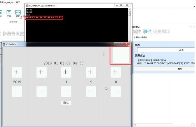 Figure 3.2 Custom Protocol Sending
4. How to add custom parsing
Click on the project to pop up the project window, click on Protocol Settings → set the protocol type to "Custom Protocol" → click on Custom Protocol Parsing Settings → pop up the Parsing Settings window → click on Add to pop up the Custom Parsing Settings window, where you can add a custom protocol parsing according to your needs and requirements, as shown in Figure 4.1.
Figure 3.2 Custom Protocol Sending
4. How to add custom parsing
Click on the project to pop up the project window, click on Protocol Settings → set the protocol type to "Custom Protocol" → click on Custom Protocol Parsing Settings → pop up the Parsing Settings window → click on Add to pop up the Custom Parsing Settings window, where you can add a custom protocol parsing according to your needs and requirements, as shown in Figure 4.1.
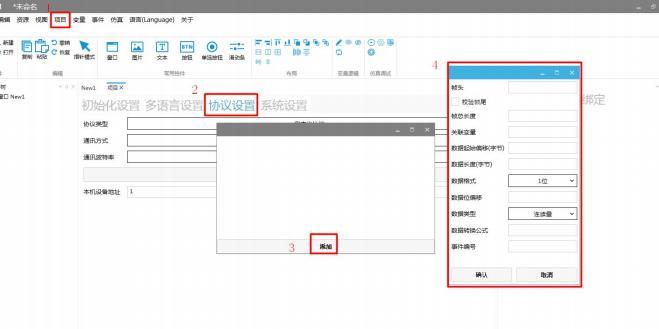 Figure 4.1 Add Custom Protocol Parsing
5. How to set custom protocol parsing
1. How to set the frame header (custom protocol parsing frame header setting)
The frame header can be input with a length of up to 10 bytes, and each parsing frame header must be different. Click on the frame header to pop up the custom instruction function description window, where you can input the instruction function in the frame header to achieve precise device parsing. For example, if you input $BYTE(#3000) in the frame header, the variable index is 0x3000, and this variable is used as an address variable. After setting the device address through the variable index 0x3000, the device can be accurately parsed through the frame header AB CD $BYTE(#3000), as shown in Figure 5.1.
Figure 4.1 Add Custom Protocol Parsing
5. How to set custom protocol parsing
1. How to set the frame header (custom protocol parsing frame header setting)
The frame header can be input with a length of up to 10 bytes, and each parsing frame header must be different. Click on the frame header to pop up the custom instruction function description window, where you can input the instruction function in the frame header to achieve precise device parsing. For example, if you input $BYTE(#3000) in the frame header, the variable index is 0x3000, and this variable is used as an address variable. After setting the device address through the variable index 0x3000, the device can be accurately parsed through the frame header AB CD $BYTE(#3000), as shown in Figure 5.1.
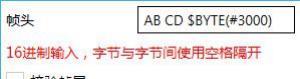 Figure 5.1 Frame Header Setting
2. How to set the frame trailer
Check the frame trailer verification, which adds a frame trailer verification. You can input data with a length of up to 10 bytes. If you do not check the frame trailer verification, it will not be added.
Figure 5.1 Frame Header Setting
2. How to set the frame trailer
Check the frame trailer verification, which adds a frame trailer verification. You can input data with a length of up to 10 bytes. If you do not check the frame trailer verification, it will not be added.
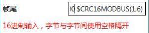 Figure 5.2 Frame Tail Settings
3. How to Set the Total Frame Length
The total frame length refers to the total length of the frame to be received, including the frame header, data bits, and frame tail, as shown in Figure 5.3.
Figure 5.2 Frame Tail Settings
3. How to Set the Total Frame Length
The total frame length refers to the total length of the frame to be received, including the frame header, data bits, and frame tail, as shown in Figure 5.3.
 Figure 5.3 Total Frame Length Settings
4. How to Set Associated Variables
Associated variables are used to associate the parsing method with the variable. The value filled in is the variable index of the variable, such as 201, which means the final parsed value is the value of variable 201. For example, the variable with index 201 is the system time year, which can be set through an instruction.
Figure 5.3 Total Frame Length Settings
4. How to Set Associated Variables
Associated variables are used to associate the parsing method with the variable. The value filled in is the variable index of the variable, such as 201, which means the final parsed value is the value of variable 201. For example, the variable with index 201 is the system time year, which can be set through an instruction.
 Figure 5.4 Associated Variable Settings
5. How to Set Data Starting Offset (Bytes)
The data starting offset byte indicates from which byte the data content in this frame starts, as shown in Figure 5.5.
Figure 5.4 Associated Variable Settings
5. How to Set Data Starting Offset (Bytes)
The data starting offset byte indicates from which byte the data content in this frame starts, as shown in Figure 5.5.
 Figure 5.5 Set Data Starting Offset Byte
6. How to Set Data Length (Bytes)
The data length byte indicates how many bytes of data follow after the data starting offset byte, as shown in Figure 5.6.
Figure 5.5 Set Data Starting Offset Byte
6. How to Set Data Length (Bytes)
The data length byte indicates how many bytes of data follow after the data starting offset byte, as shown in Figure 5.6.
 Figure 5.6 Set Data Length (Bytes)
7. How to Set Data Bit Offset
Data Bit Offset: It only appears when the selected data type is 1 bit or 2 bits. It indicates the specific bit position (starting from 0) within the selected byte. For example, if the data format is set to 1 bit and the data bit offset is 3, and the received data is 0xaa, the binary representation is: 10101010, then the value obtained at this time is 1. If the data format is set to 2 bits, 10101010, then the value obtained at this time is 01 (in binary), as shown in Figure 5.7
.
Figure 5.6 Set Data Length (Bytes)
7. How to Set Data Bit Offset
Data Bit Offset: It only appears when the selected data type is 1 bit or 2 bits. It indicates the specific bit position (starting from 0) within the selected byte. For example, if the data format is set to 1 bit and the data bit offset is 3, and the received data is 0xaa, the binary representation is: 10101010, then the value obtained at this time is 1. If the data format is set to 2 bits, 10101010, then the value obtained at this time is 01 (in binary), as shown in Figure 5.7
.
 Figure 5.7 Set Data Bit Offset
8. How to Set Data Format
1 bit: For a single byte, such as 0x41, its binary representation is 01000001, where each bit is counted from right to left. For example, the first bit is 1,
the second bit is 0, and so on.
2 bits: Similar to 1 bit, it is calculated in binary, but takes two bits, such as 01 or 00.
1 byte: The data format is a single byte, such as a1.
2 bytes (with high byte first): If the data is 1, then the received data must be 00 01
2 bytes (with low byte first): If the data is 1, then the received data must be 01 00
4 bytes (big-endian): If the data is 1, the received data must be 00 00 00 01.
4 bytes (little-endian): If the data is 1, the received data must be 01 00 00 00.
As shown in Figure 5.8.
Figure 5.7 Set Data Bit Offset
8. How to Set Data Format
1 bit: For a single byte, such as 0x41, its binary representation is 01000001, where each bit is counted from right to left. For example, the first bit is 1,
the second bit is 0, and so on.
2 bits: Similar to 1 bit, it is calculated in binary, but takes two bits, such as 01 or 00.
1 byte: The data format is a single byte, such as a1.
2 bytes (with high byte first): If the data is 1, then the received data must be 00 01
2 bytes (with low byte first): If the data is 1, then the received data must be 01 00
4 bytes (big-endian): If the data is 1, the received data must be 00 00 00 01.
4 bytes (little-endian): If the data is 1, the received data must be 01 00 00 00.
As shown in Figure 5.8.
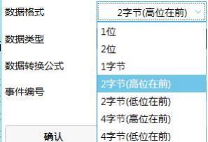 Figure 5.8 Data format setting
9. How to set the data type
Switch value: This must be read in conjunction with the data comparison column:
Figure 5.8 Data format setting
9. How to set the data type
Switch value: This must be read in conjunction with the data comparison column:
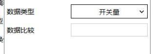 When the obtained data content is exactly the same as the value entered in the data comparison, the data value is 1; otherwise, it is 0. If the data comparison is set to: 26 14, and the received data is 26 14, then the data is correct, and the switch value becomes on, that is, 1; otherwise, the switch value is off, that is, 0, thus achieving the purpose of switching. 1-bit data comparison is compared with 0 and 1, and 2-bit data is extracted as 0, 1, 2, 3, so the comparison data is 0-3.
Continuous quantity:
When the obtained data content is exactly the same as the value entered in the data comparison, the data value is 1; otherwise, it is 0. If the data comparison is set to: 26 14, and the received data is 26 14, then the data is correct, and the switch value becomes on, that is, 1; otherwise, the switch value is off, that is, 0, thus achieving the purpose of switching. 1-bit data comparison is compared with 0 and 1, and 2-bit data is extracted as 0, 1, 2, 3, so the comparison data is 0-3.
Continuous quantity:
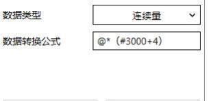 In continuous quantity, corresponding formulas can be filled in. If not filled in, then the received data is the original data. If a formula is added, as shown in the figure above: @ represents the received data, #3000 represents variable 3000, and all variables must be prefixed with a #.
10. How to set the event number
Set event processing, that is, after receiving and parsing the instruction, execute the event processing method simultaneously, and fill in the event processing number, as shown in Figure 5.9.
In continuous quantity, corresponding formulas can be filled in. If not filled in, then the received data is the original data. If a formula is added, as shown in the figure above: @ represents the received data, #3000 represents variable 3000, and all variables must be prefixed with a #.
10. How to set the event number
Set event processing, that is, after receiving and parsing the instruction, execute the event processing method simultaneously, and fill in the event processing number, as shown in Figure 5.9.
 Figure 5.9 Set event number
6. How to set event handling
Setting event handling involves executing event handling methods simultaneously after receiving and parsing instructions.
1. How to add event handling
Click on "Events" in the menu bar, select "Event Handling" → a window for event handling will pop up → click "Add" → set the event number (event numbers range from 100 to 65535) as shown in Figure 6.1.
Figure 5.9 Set event number
6. How to set event handling
Setting event handling involves executing event handling methods simultaneously after receiving and parsing instructions.
1. How to add event handling
Click on "Events" in the menu bar, select "Event Handling" → a window for event handling will pop up → click "Add" → set the event number (event numbers range from 100 to 65535) as shown in Figure 6.1.
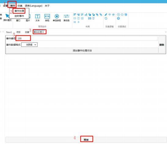 Figure 6.1 Adding Event Handling
2. How to set data format
Set the data format by specifying the data type, as shown in Figure 6.2.
Figure 6.1 Adding Event Handling
2. How to set data format
Set the data format by specifying the data type, as shown in Figure 6.2.
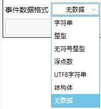 Figure 6.2 Setting Data Format
3. How to set handling methods
Click "Add Event Handling Method" → click the "..." button to pop up the handling method window → set the handling method according to the setting requirements (an event can
add multiple handling methods), as shown in Figure 6.3.
Figure 6.2 Setting Data Format
3. How to set handling methods
Click "Add Event Handling Method" → click the "..." button to pop up the handling method window → set the handling method according to the setting requirements (an event can
add multiple handling methods), as shown in Figure 6.3.
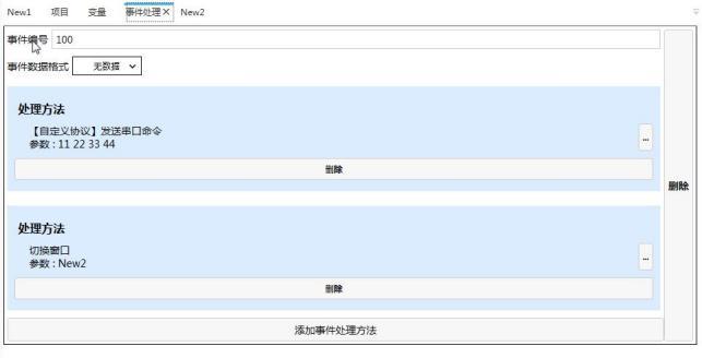 Figure 6.3 Adding Event Handling Methods
4. Simulation Demonstration
Upon receiving the command AB CD 00 07 E4 00 CE D1, the system time year is modified to 2020, and the interface switches to the NEW2 window while sending the command 11 22 33 44
Before command parsing, as shown in Figure 6.4
Figure 6.3 Adding Event Handling Methods
4. Simulation Demonstration
Upon receiving the command AB CD 00 07 E4 00 CE D1, the system time year is modified to 2020, and the interface switches to the NEW2 window while sending the command 11 22 33 44
Before command parsing, as shown in Figure 6.4
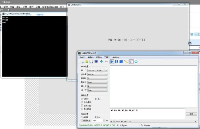 Figure 6.4 Simulation Demonstration
After command parsing, as shown in Figure 6.5.
Figure 6.4 Simulation Demonstration
After command parsing, as shown in Figure 6.5.
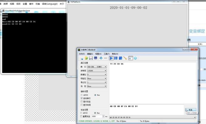 Figure 6.5 Simulation Demonstration
7. How to Trigger Events Through Custom Command Parsing
There are two types of triggering events through custom command parsing: triggering by comparing switch values and direct triggering by continuous values
1. Triggering by switch values, with the following settings:
Figure 6.5 Simulation Demonstration
7. How to Trigger Events Through Custom Command Parsing
There are two types of triggering events through custom command parsing: triggering by comparing switch values and direct triggering by continuous values
1. Triggering by switch values, with the following settings:
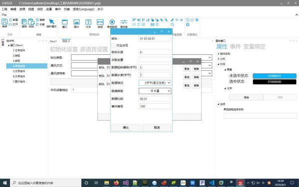 The associated variable is not filled in, the frame tail is optionally filled in, and the other fields are required. This means that when the length, data length, and frame header (frame tail) match, the event with the number 100 is triggered based on whether the data is 00 01 (which must correspond to the data format).
2. Direct triggering, with the following settings:
The associated variable is not filled in, the frame tail is optionally filled in, and the other fields are required. This means that when the length, data length, and frame header (frame tail) match, the event with the number 100 is triggered based on whether the data is 00 01 (which must correspond to the data format).
2. Direct triggering, with the following settings:
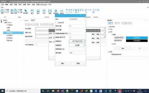 The conversion formula and associated variable are not filled in, the frame tail is optionally filled in, and the other fields are required. When the length, data length, and frame header (frame tail) match, the event is directly triggered.
If you have gained something, please give a like


Leave a Reply