
1. Introduction to Circular Gauge
Circular gauges are commonly used in situations where a dial display is required, such as on a thermometer dial. In these cases, a circular gauge control is necessary.
2. How to Add a Circular Gauge
Open or create a new project, click on the standard controls in the toolbox, and then click on the circular gauge icon to add the control, as shown in Figure 2.1.
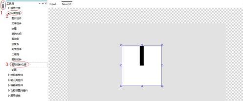 Figure 2.1 Adding a Control
3. How to Replace the Image
Select the circular gauge, click on the property window on the right, and you can modify the image. The background is the base image of the circular gauge, and the pointer is the actual pointer of the circular gauge, as shown in Figure 3.1.
Figure 2.1 Adding a Control
3. How to Replace the Image
Select the circular gauge, click on the property window on the right, and you can modify the image. The background is the base image of the circular gauge, and the pointer is the actual pointer of the circular gauge, as shown in Figure 3.1.
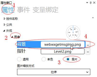 Figure 3.1 Image Replacement
During simulation, the circular gauge displays the replaced image, as shown in Figure 3.2.
Figure 3.1 Image Replacement
During simulation, the circular gauge displays the replaced image, as shown in Figure 3.2.
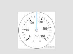 Figure 3.2 Simulation Demonstration
4. How to Set Miscellaneous Items
Click on the property window on the right to access the settings for miscellaneous items
Figure 3.2 Simulation Demonstration
4. How to Set Miscellaneous Items
Click on the property window on the right to access the settings for miscellaneous items
 The pointer offset angle and the horizontal and vertical coordinates of the center of the circle can be set for the circular pointer gauge, as shown in Figure 4.1.
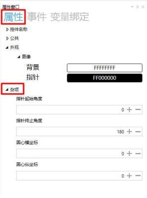 Figure 4.1 Miscellaneous Settings
4.1 How to Set the Pointer Offset Angle
Click the input box under "Pointer Start/End Angle" to set the pointer start/end angle via the keyboard or the "+" and "-" buttons. Setting the pointer angle means setting the range within which the circular pointer gauge can be dragged. The default pointer start angle is 0°, and the default pointer angle is 180°. The pointer can be dragged within this range.
When the pointer start angle is -50° and the pointer end angle is 250°, the circular pointer gauge displays as -50°-250°, and the pointer can only slide within this area, as shown in Figure 4.2.
Figure 4.1 Miscellaneous Settings
4.1 How to Set the Pointer Offset Angle
Click the input box under "Pointer Start/End Angle" to set the pointer start/end angle via the keyboard or the "+" and "-" buttons. Setting the pointer angle means setting the range within which the circular pointer gauge can be dragged. The default pointer start angle is 0°, and the default pointer angle is 180°. The pointer can be dragged within this range.
When the pointer start angle is -50° and the pointer end angle is 250°, the circular pointer gauge displays as -50°-250°, and the pointer can only slide within this area, as shown in Figure 4.2.
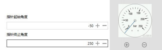 Figure 4.2 Pointer Start/End Angle
4.2 How to Set the Horizontal and Vertical Coordinates of the Center of the Circle
Click the input box for the horizontal and vertical coordinates of the center of the circle to set the horizontal and vertical coordinates of the center of the circle via the keyboard or the "+" and "-" buttons. After replacing the base image of the circular pointer gauge, if the center of the base image is not at the midpoint, you need to find the center of the circle by setting the horizontal and vertical coordinates of the center. The position of the horizontal and vertical coordinates of the center of the circle is related to the height and width of the circular slider, as shown in Figure 4.3.
Figure 4.2 Pointer Start/End Angle
4.2 How to Set the Horizontal and Vertical Coordinates of the Center of the Circle
Click the input box for the horizontal and vertical coordinates of the center of the circle to set the horizontal and vertical coordinates of the center of the circle via the keyboard or the "+" and "-" buttons. After replacing the base image of the circular pointer gauge, if the center of the base image is not at the midpoint, you need to find the center of the circle by setting the horizontal and vertical coordinates of the center. The position of the horizontal and vertical coordinates of the center of the circle is related to the height and width of the circular slider, as shown in Figure 4.3.
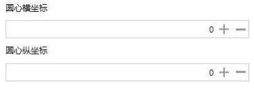 Figure 4.3 Horizontal and Vertical Coordinates of the Center of the Circle
5. How to Set the Pressure Dial via the Circular Pointer Gauge
Display the current pressure through the dial, and adjust the pressure through the "+" and "-" buttons. The specific operation steps are as follows
1. How to Add Controls
Open or create a new project, click on the standard controls in the toolbox, click on the button and circular pointer gauge icons, add a circular pointer gauge and two button controls, as shown in Figure 5.1.
Figure 4.3 Horizontal and Vertical Coordinates of the Center of the Circle
5. How to Set the Pressure Dial via the Circular Pointer Gauge
Display the current pressure through the dial, and adjust the pressure through the "+" and "-" buttons. The specific operation steps are as follows
1. How to Add Controls
Open or create a new project, click on the standard controls in the toolbox, click on the button and circular pointer gauge icons, add a circular pointer gauge and two button controls, as shown in Figure 5.1.
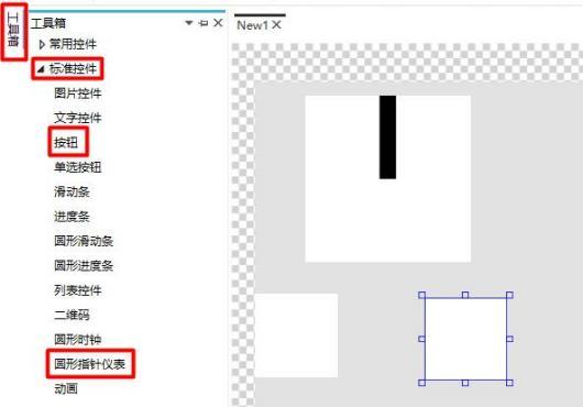 Figure 5.1 Add Controls
2. How to replace images
Select the circular pointer gauge and button controls, replace the images of the controls, and adjust the position and size of the controls. The specific steps are the same as above, as shown in Figure 5.2.
Figure 5.1 Add Controls
2. How to replace images
Select the circular pointer gauge and button controls, replace the images of the controls, and adjust the position and size of the controls. The specific steps are the same as above, as shown in Figure 5.2.
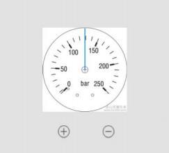 Figure 5.2 Image Replacement
3. How to set miscellaneous items
Select the circular pointer gauge, set the miscellaneous items of the circular pointer gauge. The starting angle of the pointer is -50°, and the ending angle of the pointer is 250°, as shown in Figure 5.3.
Figure 5.2 Image Replacement
3. How to set miscellaneous items
Select the circular pointer gauge, set the miscellaneous items of the circular pointer gauge. The starting angle of the pointer is -50°, and the ending angle of the pointer is 250°, as shown in Figure 5.3.
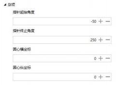 Figure 5.3 Miscellaneous Settings
4. How to set circular pointer gauge variable binding
Select the circular pointer gauge, click on "Variable Binding" in the property window on the right → click "Add" → the bound control property is "Current Value" → data source is bound to "Var0" → conversion mode is "One-way" → conversion method is "Default", as shown in Figure 5.4.
Figure 5.3 Miscellaneous Settings
4. How to set circular pointer gauge variable binding
Select the circular pointer gauge, click on "Variable Binding" in the property window on the right → click "Add" → the bound control property is "Current Value" → data source is bound to "Var0" → conversion mode is "One-way" → conversion method is "Default", as shown in Figure 5.4.
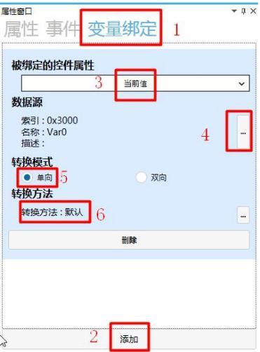 Figure 5.4 Variable Binding
Note: The Var0 variable is
Figure 5.4 Variable Binding
Note: The Var0 variable is
 5. How to set button control events
Select the "+ " button, click on "Events" in the property window on the right → click "Add" (add two events) → set the events as "Click" and "Long Press" → select "Variable Operation" for both handling methods and choose "Variable Loop Increment/Decrement" → bind the target variable to "Var0" → enter a step value of 1, as shown in Figure 5.5.
5. How to set button control events
Select the "+ " button, click on "Events" in the property window on the right → click "Add" (add two events) → set the events as "Click" and "Long Press" → select "Variable Operation" for both handling methods and choose "Variable Loop Increment/Decrement" → bind the target variable to "Var0" → enter a step value of 1, as shown in Figure 5.5.
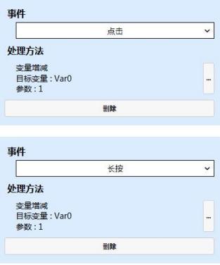 Figure 5.5 "+" Button Event Settings
Select the "-" button, click on "Events" in the property window on the right → click "Add" (add two events) → set the events as "Click" and "Long Press" → select "Variable Operation" for both handling methods and choose "Variable Loop Increment/Decrement" → bind the target variable to "Var0" → enter a step value of -1, as shown in Figure 5.6.
Figure 5.5 "+" Button Event Settings
Select the "-" button, click on "Events" in the property window on the right → click "Add" (add two events) → set the events as "Click" and "Long Press" → select "Variable Operation" for both handling methods and choose "Variable Loop Increment/Decrement" → bind the target variable to "Var0" → enter a step value of -1, as shown in Figure 5.6.
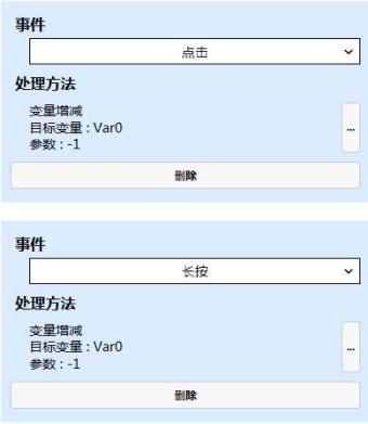
 Figure 5.6 "-" Event Settings
6. Simulation Demonstration
, pop up the simulation run button.
Click the simulation run button
Figure 5.6 "-" Event Settings
6. Simulation Demonstration
, pop up the simulation run button.
Click the simulation run button
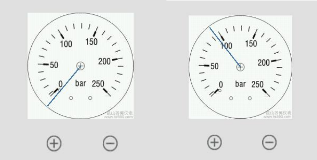 Figure 5.7 Simulation Demonstration
The pressure dial settings can be set through the "+" and "-" buttons, as shown in Figure 5.7.
Figure 5.7 Simulation Demonstration
The pressure dial settings can be set through the "+" and "-" buttons, as shown in Figure 5.7.
If you have gained something, please give a thumbs up


Leave a Reply