
1. Definition of Variables
In the TDFHUI editing tool, a variable refers to a quantity whose value can change during operation. The function of a variable is to store data. Each variable has a specific type, which determines the size and layout of the variable's storage. Values within this range can be stored in memory. Variables can be applied to events, variable binding, and so on.
To open or create a new project, click
 in the menu bar to pop up the variable window. Variables are divided into system variables and custom variables. System variables cannot be changed, added, or deleted, while custom variables allow operations such as deleting or changing the index of added variables.
It cannot be modified, added, or deleted. Custom variables can be deleted or their indexes can be changed for the added variables.
2. How to Add a Custom Variable
To open or create a new project, click
in the menu bar to pop up the variable window. Variables are divided into system variables and custom variables. System variables cannot be changed, added, or deleted, while custom variables allow operations such as deleting or changing the index of added variables.
It cannot be modified, added, or deleted. Custom variables can be deleted or their indexes can be changed for the added variables.
2. How to Add a Custom Variable
To open or create a new project, click
 in the menu bar to pop up the variable binding window. Click
 →
→
 , as shown in Figure 2.1.
.
Show
, as shown in Figure 2.1.
.
Show
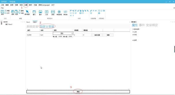 Figure 2.1 Adding a Custom Variable
3. How to Set a Custom Variable
3.1 How to Set a Custom Variable Index
After adding a variable, click the input box under the index to pop up a prompt for modification. The user can change the variable index according to the prompt. The default index is 0x3000, as shown in Figure 3.1.
Figure 2.1 Adding a Custom Variable
3. How to Set a Custom Variable
3.1 How to Set a Custom Variable Index
After adding a variable, click the input box under the index to pop up a prompt for modification. The user can change the variable index according to the prompt. The default index is 0x3000, as shown in Figure 3.1.
 Figure 3.1 Change Variable Index
3.2 How to Set Custom Variable Names
Click the input box under the name, and a modification prompt will pop up. Users can change the variable name according to the prompt. The default name is Var0, as shown in Figure 3.2
.
Figure 3.1 Change Variable Index
3.2 How to Set Custom Variable Names
Click the input box under the name, and a modification prompt will pop up. Users can change the variable name according to the prompt. The default name is Var0, as shown in Figure 3.2
.
 3.3 How to set custom variable types
Click the selection box under the type to pop up a dropdown menu, where users can make their selections according to their needs. The default type is integer, as shown in Figure 3.3.
3.3 How to set custom variable types
Click the selection box under the type to pop up a dropdown menu, where users can make their selections according to their needs. The default type is integer, as shown in Figure 3.3.
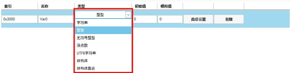 3.3.1 Definition of Integer
IntegerVariables represent data of the integer type, with their maximum and minimum values set to 10000 and -10000 by default, respectively. Integer variables are the most commonly used and have a wide range of applications.
3.3.1 Definition of Integer
IntegerVariables represent data of the integer type, with their maximum and minimum values set to 10000 and -10000 by default, respectively. Integer variables are the most commonly used and have a wide range of applications.
 3.3.2 Definition of String
Character variables are variables that storecharacter constants, whose values are ASCII string constants.
3.3.2 Definition of String
Character variables are variables that storecharacter constants, whose values are ASCII string constants.
 3.3.3 Definition of Unsigned Integer
Unsigned integer variables are data of the positive integer type, unable to represent complex numbers. Their minimum value is greater than or less than 0, and their maximum and minimum values are set to 10000 and 0 by default, respectively. The rest is the same as for integer variables.
3.3.3 Definition of Unsigned Integer
Unsigned integer variables are data of the positive integer type, unable to represent complex numbers. Their minimum value is greater than or less than 0, and their maximum and minimum values are set to 10000 and 0 by default, respectively. The rest is the same as for integer variables.
 3.3.4 Definition of Floating-Point Number
Floating-point variable refers to a real number variable (a variable that stores data that can have decimals).
3.3.4 Definition of Floating-Point Number
Floating-point variable refers to a real number variable (a variable that stores data that can have decimals).
 3.3.5 Definition of UTF8 string
UTF8 string can store Chinese data, and its settings are the same as those of a string, with the length being non-editable.
3.3.5 Definition of UTF8 string
UTF8 string can store Chinese data, and its settings are the same as those of a string, with the length being non-editable.
 3.3.6 Definition of Structures
A structure is a new data type, a constructed type, consisting of several "members" of different types; these "members" can be described using any basic data type.
3.3.6 Definition of Structures
A structure is a new data type, a constructed type, consisting of several "members" of different types; these "members" can be described using any basic data type.
 3.3.7 Definition of structure set
A structure set is a collection of multiple structures, and its usage is similar to that of a structure.
3.3.7 Definition of structure set
A structure set is a collection of multiple structures, and its usage is similar to that of a structure.
 3.4 How to Set Custom Variable Initial Values/Simulation Values
After adding a variable, click the input box under Initial Value/Simulation Value. The initial value is the default value for actual operation/simulation, and the simulation value is the effect value displayed in the UI configuration software. It is not used as the actual output. Users can set it according to their needs, as shown in Figure 3.4.
3.4 How to Set Custom Variable Initial Values/Simulation Values
After adding a variable, click the input box under Initial Value/Simulation Value. The initial value is the default value for actual operation/simulation, and the simulation value is the effect value displayed in the UI configuration software. It is not used as the actual output. Users can set it according to their needs, as shown in Figure 3.4.
 Figure 3.4 Set variable initial value/simulated value
3.5 How to set struct/struct collection
1. Add a struct/struct collection. Taking the struct as an example, as shown in Figure 3.5.
Figure 3.4 Set variable initial value/simulated value
3.5 How to set struct/struct collection
1. Add a struct/struct collection. Taking the struct as an example, as shown in Figure 3.5.
 Figure 3.5 Add struct variable
2. Set the struct members. Click the "Set" button to pop up the struct member window. Click the "Add" button to add multiple struct members. Different types of struct members can be added, as shown in Figure 3.6.
Figure 3.5 Add struct variable
2. Set the struct members. Click the "Set" button to pop up the struct member window. Click the "Add" button to add multiple struct members. Different types of struct members can be added, as shown in Figure 3.6.
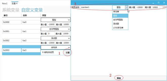 Figure 3.6 Set struct members
3. Click the struct member under the initial value/simulated value to view the added struct members and set their initial value/simulated value, as shown in Figure 3.7.
Figure 3.6 Set struct members
3. Click the struct member under the initial value/simulated value to view the added struct members and set their initial value/simulated value, as shown in Figure 3.7.
 Figure 3.7 Set initial value/simulated value
It should be noted that when setting initial values and simulated values in a structure set variable, dynamic members of the structure can be set and simulated. Clicking the "Set" button under "Initial Value/Simulated Value" will pop up a list item setting window. Clicking the "Add" button can add multiple sets of structures. The initial value/simulated value can be entered in the input box, as shown in Figure 3.8
Figure 3.7 Set initial value/simulated value
It should be noted that when setting initial values and simulated values in a structure set variable, dynamic members of the structure can be set and simulated. Clicking the "Set" button under "Initial Value/Simulated Value" will pop up a list item setting window. Clicking the "Add" button can add multiple sets of structures. The initial value/simulated value can be entered in the input box, as shown in Figure 3.8
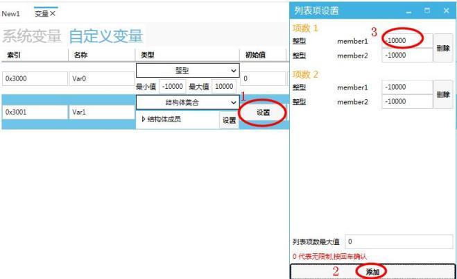 Figure 3.8: Setting Initial/Simulated Values for Structure Set
3.6 How to Set Advanced Settings for Custom Variables
Clicking the "Advanced Settings" button for a variable will pop up the VarAdv Window, where you can set its save type and protocol sending conditions. Clicking "Store" and checking the "Power-off Save" box will ensure that the original variable data is retained after rebooting, as shown in Figure 3.9
Figure 3.8: Setting Initial/Simulated Values for Structure Set
3.6 How to Set Advanced Settings for Custom Variables
Clicking the "Advanced Settings" button for a variable will pop up the VarAdv Window, where you can set its save type and protocol sending conditions. Clicking "Store" and checking the "Power-off Save" box will ensure that the original variable data is retained after rebooting, as shown in Figure 3.9
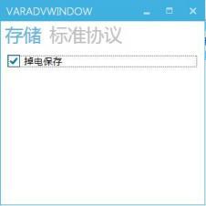 Figure 3.9: Advanced Settings for Custom Variable Storage
Clicking "Standard Protocol" and checking the "Send Message When Variable Changes" box will cause the variable protocol message to be sent externally when the variable changes, as shown in Figure 3.10
Figure 3.9: Advanced Settings for Custom Variable Storage
Clicking "Standard Protocol" and checking the "Send Message When Variable Changes" box will cause the variable protocol message to be sent externally when the variable changes, as shown in Figure 3.10
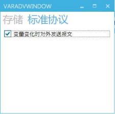 Figure 3.10: Advanced Settings for Custom Variable Protocol
4. How to Set Parameters Through Button Controls
Button controls can be used to change the display of variable data. For specific steps, refer to "How to Set Parameters Through Button Controls" in the "Button Control User Manual".
5. How to Set Parameters Through Slider Controls
Slider controls can be used to control the temperature of air conditioning. The specific setup steps are as follows:
1. Open or create a new project and add an integer variable. The specific settings are shown in Figure 5.1.
Figure 3.10: Advanced Settings for Custom Variable Protocol
4. How to Set Parameters Through Button Controls
Button controls can be used to change the display of variable data. For specific steps, refer to "How to Set Parameters Through Button Controls" in the "Button Control User Manual".
5. How to Set Parameters Through Slider Controls
Slider controls can be used to control the temperature of air conditioning. The specific setup steps are as follows:
1. Open or create a new project and add an integer variable. The specific settings are shown in Figure 5.1.
 Figure 5.1 Add Integer Variable
2. Add a slider and a text control. The slider is used to control the temperature, and the text control is used to display the currently set temperature, as shown in Figure 5.2.
Figure 5.1 Add Integer Variable
2. Add a slider and a text control. The slider is used to control the temperature, and the text control is used to display the currently set temperature, as shown in Figure 5.2.
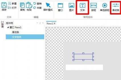 Figure 5.2 Add Controls
3. Select the text control and click Variable Binding in the property window on the right → click Add → Bound Control Property "Text 1" → Data Source Binding "Var0" → Conversion Mode "One-way" → Conversion Method "Default", as shown in Figure 5.3.
Figure 5.2 Add Controls
3. Select the text control and click Variable Binding in the property window on the right → click Add → Bound Control Property "Text 1" → Data Source Binding "Var0" → Conversion Mode "One-way" → Conversion Method "Default", as shown in Figure 5.3.
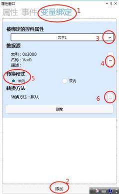 Figure 5.3 Text Control Variable Binding
4. Select the slider and click Variable Binding in the property window on the right → click Add → Bound Control Property "Current Value" → Data Source Binding "Var0" → Conversion Mode "Two-way" → Conversion Method "Default", as shown in Figure 5.4.
Figure 5.3 Text Control Variable Binding
4. Select the slider and click Variable Binding in the property window on the right → click Add → Bound Control Property "Current Value" → Data Source Binding "Var0" → Conversion Mode "Two-way" → Conversion Method "Default", as shown in Figure 5.4.
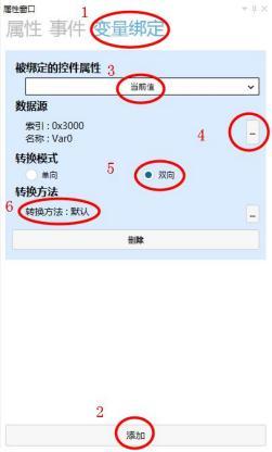 Figure 5.4 Slider Variable Binding
5. Click the simulation run button to pop up the simulation run window. Drag the slider to adjust the temperature, as shown in Figure 5.5.
Figure 5.4 Slider Variable Binding
5. Click the simulation run button to pop up the simulation run window. Drag the slider to adjust the temperature, as shown in Figure 5.5.
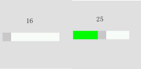 Figure 5.5 Simulation Demonstration
6. Users can send protocol instructions to set the current temperature. For specific operational steps, refer to the protocol for sending instructions.
6. How to display the week through the text control
By binding the system variable "System Time - Weekr" to the text control, the current week can be displayed.
1. Click on the text control in the common module and add two text controls, one for displaying the week and one for displaying the time, as shown in Figure 6.1.
Figure 5.5 Simulation Demonstration
6. Users can send protocol instructions to set the current temperature. For specific operational steps, refer to the protocol for sending instructions.
6. How to display the week through the text control
By binding the system variable "System Time - Weekr" to the text control, the current week can be displayed.
1. Click on the text control in the common module and add two text controls, one for displaying the week and one for displaying the time, as shown in Figure 6.1.
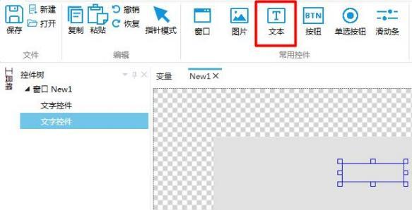 Figure 6.1 Add Text Controls
2. Click on the "System Time Settings (Button Method)" in the toolbox and add it to quickly modify the current time, as shown in Figure 6.2.
Figure 6.1 Add Text Controls
2. Click on the "System Time Settings (Button Method)" in the toolbox and add it to quickly modify the current time, as shown in Figure 6.2.
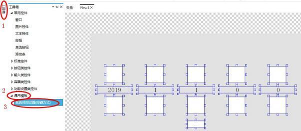 Figure 6.2 Add System Time Settings (Shortcut)
3. Select one of the text controls and click on "Text" under "Appearance" in the property window on the right to add multiple texts, as shown in Figure 6.3.
Figure 6.2 Add System Time Settings (Shortcut)
3. Select one of the text controls and click on "Text" under "Appearance" in the property window on the right to add multiple texts, as shown in Figure 6.3.
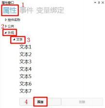 Figure 6.3 Add Multiple Texts
4. Click on Text 1, select "Static Text", and enter "Monday" in the input box. Other text operations are the same as Text 1, as shown in Figure 6.4.
Figure 6.3 Add Multiple Texts
4. Click on Text 1, select "Static Text", and enter "Monday" in the input box. Other text operations are the same as Text 1, as shown in Figure 6.4.
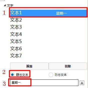 Figure 6.4 Set Text Content
5. Click on "Variable Binding" in the property window on the right, select "Add", set the "Control Property to be Bound" as "Text Index", bind the data source to "System Time - Weekr", set the "Conversion Mode" as "One-way", and set the "Conversion Method" as "Default", as shown in Figure 6.5.
Figure 6.4 Set Text Content
5. Click on "Variable Binding" in the property window on the right, select "Add", set the "Control Property to be Bound" as "Text Index", bind the data source to "System Time - Weekr", set the "Conversion Mode" as "One-way", and set the "Conversion Method" as "Default", as shown in Figure 6.5.
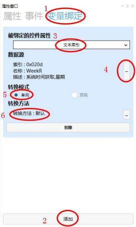 Figure 6.5 Variable Binding Settings
Note: The data source is bound to the variable "System Time - Weekr", as shown in Figure 6.6.
Figure 6.5 Variable Binding Settings
Note: The data source is bound to the variable "System Time - Weekr", as shown in Figure 6.6.
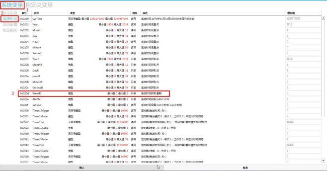 Figure 6.6 Weekr Variable
6. Select another control to set the time display. For specific setting methods and steps, refer to the "Time Setting" manual.
7. Click the simulation run button
Figure 6.6 Weekr Variable
6. Select another control to set the time display. For specific setting methods and steps, refer to the "Time Setting" manual.
7. Click the simulation run button
 . The simulation run window will pop up. Set the time and date, and the corresponding week display will change, as shown in Figure 6.7.
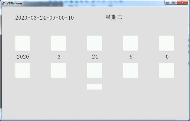
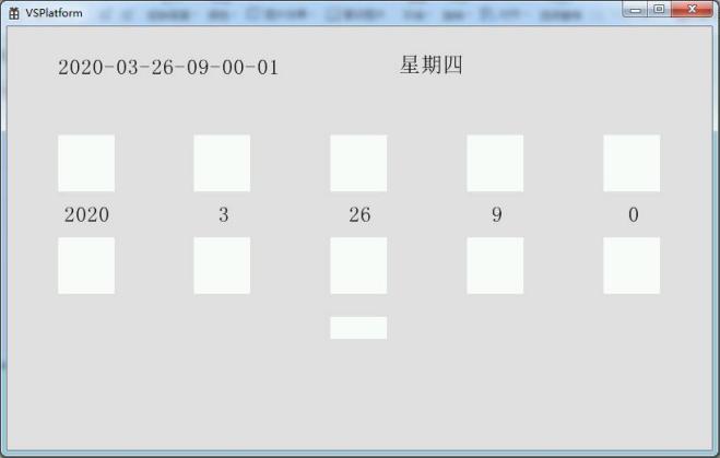 Figure 6.7 Simulation demonstration
G enters the fan period 0X3000
Advanced setting
0XF000 cannot be master
with value
give value
0X300G
delete ball
VAR0
1000
quantity small village
buy type
big hundred
10000
Name
Forbidden Type
Ke 2]
0
The length should be less than 15 characters
and consist of letters and numbers.
The name can only consist of letters
10000
Advanced Settings
VARO
0X3000
Simulated value
10000
Initial hash value
Maximum value
Long minimum value
Delete
Name
Integer
Index
Type
Unsigned integer
Structural body fusion
Advanced setup
UTF8 string
String
Delete
Floating-point number
Structural body
Initial value
Value
X3000
Lattice type
Type
VAR0
Integer
Introduction
Mingcai
0
Advanced settings
-10000 Maximum value
0X3002
10000
Floating-point number
-10000
Delete
Minimum value
VAR2
Signal 10000
UTF8 string
Advanced Settings
0X3003
Except
Large Length Word Generation
VAR3
Structure Member
Structure Member
Structure Member
Structure
0X3004
Advanced Settings
VAR4
DELETE
DESIGNER
0X3005
Advanced Settings
Structure Set
Structure Member
VAR5
Set
DELETE
Set Anonymity
Settings
-10000 to 1
10000
Initial Value
Simulation Value
Minimum Value
Advanced Settings
Type
Name
VAR0
Delete
0X3000
element reference
integer
If you have gained something, please give a thumbs up


Leave a Reply