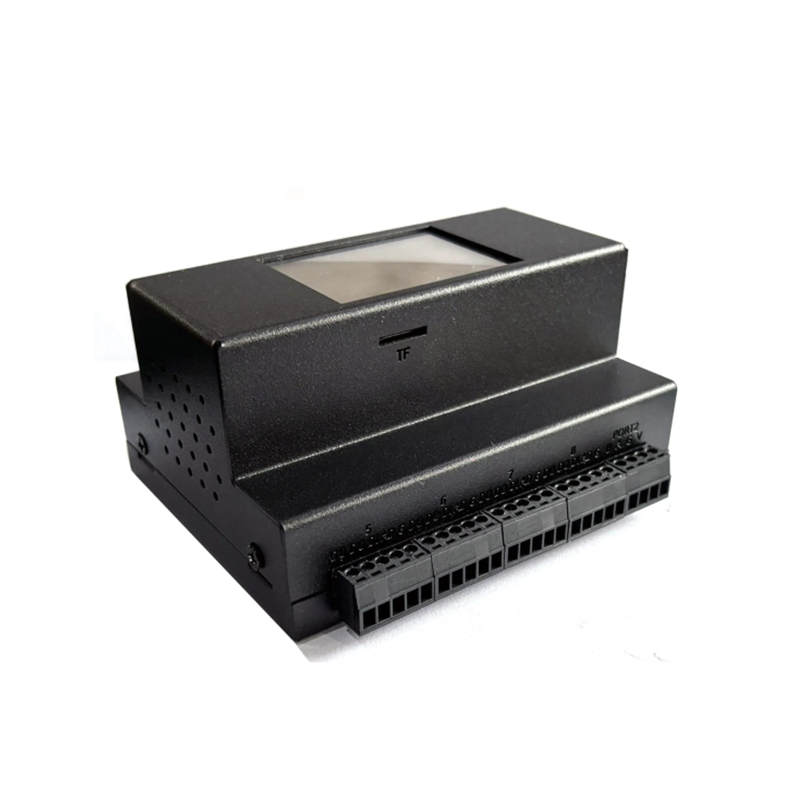
I. Product Overview
The DDC808 module is an industrial control module with high functional integration, strong flexibility, and easy operation. It has multiple input and output module configurations and can be widely used in industrial automation, building control, environmental monitoring, and other fields. This module has two physical ports, port one supports selecting Modbus RTU communication; Port 2 supports the selection of Modbus RTU (standard) or Loramish (optional) communication methods.
The module comes standard with 8 DI (digital input) and 8 DO (digital output) modules, and supports optional selection of 8 pluggable modules, including various types of AI (analog input) modules (such as 0-10V, 4-20mA, NTC10K, PT1000) and AO (analog output) modules (such as 0-10V, 4-20mA). Its design can not only read the raw AD analog signals of AIAO (ranging from 0-1024), but also implement a user readable calculation conversion process through screen matching, greatly enhancing the practicality and usability of the module.
II. Module read/write
provides five Modbus poll files through the Modbus poll tool to read/write devices, which supports Modbus RTU and Modbus TCP for read/write operations. The functions of each file are as follows:
- CONFIG: used to set module addresses (1-254), supporting a universal address of 255; Configurable baud rates for Port 1 and Port 2 (range 1200-112200). Please note that the value marked as' nochange 'cannot be modified, otherwise it may cause the system to crash.
- DI1-8: Used to read the status of 8 digital inputs, with 0 indicating off and 1 indicating on.
- DO1-8: Used for reading and writing 8 digital outputs, with 0 indicating off and 1 indicating on.
- AIAO (Original AD Value): When inserting AI or AO modules, the corresponding analog AD values (range 0-1024) of AI1-8 or AO1-8 can be read.
- AIAO Transfer Register (Calculated Value): When inserting AI or AO modules, the calculated converted values of AI1-8 or AO1-8 can be read. After the screen reads the analog AD value of the AI module and calculates the conversion, the result is stored in this register. If the screen fails, the file register displays a value of 0.
III. Screen Interface
The module is equipped with an intuitive and easy-to-use screen interface, which is convenient for users to operate and set up. It mainly includes the following interfaces:
(1) Homepage
The homepage has three main controls:
- Dispay: Click to enter the DI/DO/AI/AO interface, which is used to view and control the status of various input and output modules.
- SettingClick to enter the system settings interface, where you can configure screen backlight, buzzer, etc.
- Main switch buttonControl the automatic calculation and conversion function of the equipment. When the button pops up and turns gray, the calibration function is disabled, and the screen can only perform DI/DO reading control and AI/AO manual calibration; When the button is blue, the automatic calculation and conversion function of the device takes effect, supporting remote modification of time, timed effectiveness in schedule management, and other functions.
(2) Dispay (DI/DO/AI/AO display interface)
- DI/DO interfaceThe left displays the status of DI1-8, and the right button is used to display and control the DO1-8 module. Gray indicates off, and white indicates on.
- AI08 interfaceClick on the text control to enter the AI module settings interface. The AI module supports four types (0-10V, 4-20mA, NTC10K, PT1000), and the module type needs to be selected and calibrated according to the actual situation. The calibration range varies depending on the module type. For example, the calibration range of 0-10V modules is divided into six values: 1V, 3V, 5V, 7V, 9V, and 10V. Calibration is completed by manually inputting the corresponding AD value.
- AO08 interfaceClick on the corresponding control to input numbers to control the output of the AO module, or enter the AO module settings interface. The AO module supports two types (0-10V, 4-20mA), which need to be selected and calibrated according to the actual situation. For example, the calibration range of the 0-10V module is divided into six values: 1V, 3V, 5V, 7V, 9V, and 10V. Calibration is completed by inputting the corresponding values and adjusting the output.
(3) Setting (setting interface)
It mainly includes three controls:
- BacklightAdjust the screen backlight by dragging the progress bar, which defaults to 100%.
- BuzzerControl the buzzer. By default, press to turn it on, and when it pops up in gray, it indicates off.
- RTCLong press can modify the time on the screen, but the screen does not have RTC function and will not continue to run after power failure.
4, Disclaimer
All services provided by the DDC808 module are intended to assist customers in accelerating product development progress. The routine programs, technical documents, CAD drawings, and other materials and information provided during the service process or through other channels are for reference only. Customers have the right to choose whether to use or modify them themselves. The company does not guarantee the integrity, reliability, etc. of these materials and information. If the customer causes special, incidental, or indirect losses during use for any reason, the company shall not be held responsible.


Leave a Reply