
Source: Modbus Chinese Network (modbus. cn) - a leading Modbus communication protocol technology community in China
The complete byte stream received, including frame header, address, function code, data, and checksum, is displayed in full. Used to troubleshoot frame structure issues - such as discovering that the number of received bytes is insufficient, possibly due to a short interval being truncated.
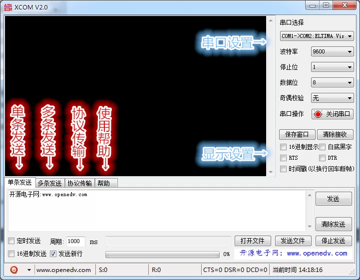
Summary:ATK-XCOM V3.0 Developed by Zhengdian Atom (ALIENTEK), it is one of the most widely used serial debugging tools in the domestic embedded development community. This article not only covers its core functions, but also provides a more in-depth explanation of its protocol transmission mode——Automatic timeout resend, checksum/XOR/CRC8/CRC16 Four types of verification, separation and display of data frames from actual data——These functions enable ATK-XCOM In Modbus RTU In debugging scenarios, it is one level higher than a regular serial assistant. Accompanied by complete Modbus Debugging operation guide and comparison with similar tools. Keywords:ATK-XCOM, Accurate Atom, Serial Debugging Assistant, Protocol TransmissionModbus RTU DebuggingCRC16Verify the sum.
Debugging serial ports is simple and straightforward——Find a serial assistant and select the right one COM What do you see after sending a hexadecimal frame with the port and baud rate. It's also difficult to say——When your frame is sent out, the device responds, but you don't know if the data returned is correct, if the frame was lost, or if the two bytes in the middle are the correct checksum.
ATK-XCOM V3.0 It is a serial debugging tool developed by the Zhengdian Atomic team. The influence of Zhengdian Atom in the domestic embedded circle goes without saying——STM32 Development boardESP32 ModuleRT-Thread Tutorial: Basically, people who learn embedded systems have used their tools.ATK-XCOM It is an externalized version of their internal debugging tools, with functionality built from real development scenarios rather than being designed out of thin air.
1、 How to install software
Developer: Zhengdian Atom (ALIENTEK), a professional embedded development solution provider in China. Long term focus on providing development boards, modules, and supporting tools for engineers, students, and enthusiasts.
System requirements:Windows 7 And above,32/64 All positions are supported. Tested in Windows 10 And Windows 11 Stable operation on the platform,CH340, CP2102, FT232 Commonly seen USB The serial port chips are all recognized normally.
2、 Quick overview of basic functions
2.1 Serial port settings
After opening the software, it automatically scans all available serial ports, and the corresponding serial port names and detailed information (such as COM3: USB-SERIAL CH340) can be seen in the serial port drop-down list. common CH340 The chip supports hot swapping——USB After plugging in, click refresh to appear, and it will automatically disappear after unplugging. Some older drivers may need to manually turn off the serial port and then turn it back on.
Baud rate range: preset 1200 ~ 1382400 bpsIt covers all standard rates. When a non-standard baud rate (such as 750000, 921600) is required, click the "Customize" button while the serial port is closed and enter the value directly. The premise is yours USB Convert the serial port chip to the other device UART All can support this speed——STM32 of In USART The non-standard baud rate range supported by the clock is very narrow and cannot be stabilized by simply inputting a number. 72MHz Stop position: 1
Three types. Data bits: 5, 6, 71.5, 2 Four people. Check bits: no check, odd check, even check.8 Standard configuration:Modbus RTU Data bits8 Stop bit, even check, or no check.1 Display and send
2.2 The receiving area supports two display modes: hexadecimal and
It can be switched in real-time. Two color schemes: the classic "black background with green text" (similar to terminal style, not glaring when looking at the screen for a long time) and "white background with black text" (similar to document style, screenshot available). Checking 'timestamp' can add precise time to each received data. Pay attention to the timestamp ASCIIFor frame boundaries rn If you receive it——There is exactly in the middle of the frame Modbus The timestamp will be mistakenly inserted into the frame. So 0D 0AIt is recommended to use timestamp function during debugging Modbus Used in mode, ASCII Used in mode,Hex It is recommended to turn it off in mode.
Sending area support ASCII There are two input formats: hexadecimal and hexadecimal. Check 'Send New Line' to automatically add it at the end of the sent content rn——Adjustment AT The module of the instruction (e.g. module) must be checked. Shortcut keys ESP8266, 4G Can be sent directly. Ctrl+Enter Timer sending function: It can set a fixed period (millisecond level), and the software automatically sends the content of the sending area in a loop at intervals. Suitable for conducting aging tests
For example, give——Continuous transmission from the station Modbus Read the register command hourly to see if the device will experience communication interruption. 24 File sending function: It can send any format of file (such as firmware, upgrade package) as a byte stream through the serial port, with a progress bar and pause/resume control.
)When upgrading firmware to a serial port, use it directly without the need to write a separate upgrade tool. .bin Multiple sending and instruction management.hex Four independent sending pages, each page hasIAP (In-Application ProgrammingEditable send commands (equal to a maximum of
2.3 preset commands). The sending format (
), whether to add a new line, and sending cycle of each instruction can be configured separately. Digital keyboard 10 Can be bound to the current page 40 InstructionsHex/ASCIISuitable for scenarios that require quick response control, such as smart car control (pressing number keys 0~9 forward, backward, left turn). 1~10 The instruction set supports exporting as——Format, also from 1 Import. When handing over the project, directly export all your testing instructions into a file and send it to your colleagues. Once they import it, they can use the exact same commands to debug.2 3、 Protocol transmission mode3 The killer move
This is Excel The essential difference between it and a regular serial port assistant lies in. Most serial assistants simply say, 'If you send a byte, it will be displayed if there is a response.'. Excel The protocol transmission mode does three things: automatic verification, automatic timeout retransmission, and separate display of data and frames.
working principle——ATK-XCOM The basic process of protocol transmission: You fill in the actual data to be sent in the sending area (
automatically add a frame header and checksum before and after the data, assemble it into a complete protocol frame, and send it out through the serial port. After receiving the frame, the receiving end calculates the checksum. If the checksum passes, it returns a confirmation frame ( ATK-XCOM ), and the sending end receives itATK-XCOM Indicates successful transmission. If not received within the set time
3.1 Automatically resend, the maximum number of times to retry the configuration.
ForPayload) , ATK-XCOM It's not necessary to use a complete setACKThe mechanism itself has its own master-slave question answering protocol, but it supports four verification algorithms and has the function of separating "displaying raw frames" and "displaying actual data" ACK These two are in ACKDebugging is too practical.
Four verification methods Modbus RTU Verification method Send-Ack LengthModbus Algorithm description——Applicable scenarios Modbus Checksum (
3.2 byte
| sum of all data bytes, taking the low bit | simple protocol, custom frame | XOR ( | byte |
|---|---|---|---|
| continuous XOR of all data bytesChecksum) | 1 ), partial sensor | All data bytes are accumulated, with the lowest value taken 8 bit | Simple protocol, custom frame |
| XOR(XOR) | 1 byte | All data bytes are consecutive XOR | NMEA 0183 (GPS)Partial sensors |
| CRC8 | 1 Byte | 8 Bit cycle redundancy check, polynomial configurable | Dallas 1-Wire, SMBus |
| CRC16 | 2 Byte | 16 Bit cycle redundancy check, implemented by lookup table method | **Modbus RTU**(Polynomial 0xA001) |
Select "CRC16, ATK-XCOM in the protocol transmission settings Modbus Automatically0xA001Standard Polynomial ( Modbus RTU ) calculation, the result is low byte first, high byte last (small end order), completely in accordance with the sorting rule of CRC . You only need to input the bare frame except for CRC , and the software will add two bytes for you CRC.
3.3 Display the original frame vs Display the actual data
The receiving area can switch between two modes: Display the original frame
- Display the received complete byte stream, including frame header, address, function code, data, and checksum, all displayed. Used to troubleshoot frame structure problemsFor example, if the number of received bytes is too small, it may be truncated due to a short fixed time interval——Display the actual data
- Only display the valid data after verification. Data payload, all frame headers and checksum are stripped. Used for quick viewing of data contentThere is no need to search for "where data starts and where verification ends" in hexadecimal.——The switching between these two modes during debugging is as follows: first, use "Display Original Frame" to confirm that the frame structure is correct and the checksum passes. After confirming that there are no errors, switch to 'Display Actual Data' and only focus on the changes in the register values.
Modbus Automatic resend and timeout configuration
3.4 The retry mechanism after sending failure can be configured with three parameters:
The maximum time for timeout (
- : waitingms) ). For slave stations, the typical value is set to be sufficient, depending on the response speed of the slave station device. Some low-speed devices (old ACK microcontroller running Modbus baud rate) may need to be set to 100~500ms Even higher. 51 Resend frequency 4800 The maximum number of automatic resending after timeout. Set up 800ms Indicates not to resend. General setting
- Secondly.Resend interval ( 0 : the interval between two retransmissions. This value requires a timeout, otherwise the logic will be confused. For the scenario of 3~5 , the frame interval must be
- character time (ms) baud rate), for example > It's about agreement Modbus RTU These parameters are placed in one ≥ 3.5 On the panel, it is much more intuitive than writing code with serial port timeout. The key is to visually see how many times the correct message was received during the resend. If it only succeeds after the first attempt, it indicates that there is instability in the communication link and cable or interference needs to be investigated. The complete process of using and debugging is as follows: Step 1: Configure the serial port parameters3.5 × 11 / Open 9600 bps Select the corresponding port. Set the baud rate (or the actual baud rate of the device), data bit, stop bit, check bit, select none or even check 4ms.
depending on the specific configuration of your device. Click on "Open Serial Port". If the circuit is correct and the device is powered on, the status bar will display that the serial port is open and the number of bytes sent and received is from GUI Start. ACK——If every time it reaches the end 3 The success of the second attempt indicates that there is instability in the communication link, and it is necessary to investigate the cables or interference.
4、 Use ATK-XCOM debug Modbus RTU The complete process
Step 1: Configure serial port parameters
open ATK-XCOM V3.0, select the corresponding one COM Mouth. Baud rate setting 9600(or actual baud rate of the device), data bits 8Stop position 1Select 'none' or 'even' as the checksum——It depends on the specific configuration of your device.
Click on 'Open Serial Port'. If the circuit is correct and the device is powered on, the status bar will display that the serial port is open, and the number of bytes sent and received is from 0 Start.
Step 2: Construction Modbus Query frame
If reading the address of the slave station 01 Maintain registers 40001(Address 0x0000), read 1 A register. The bare frame (excluding CRC) is:
01 03 00 00 00 01Check 'Hexadecimal Send' and enter ' 010300000001' in the sending area CRC16 . Check in the 'Protocol Transmission' settingsATK-XCOM Verification, CRC It will automatically calculateCRC And add two bytes at the end of the frame (for this frame, 0x840AYes 01 03 00 00 00 01 84 0A, the complete frame sent is
). Click to send.
Step 3: Analyze the returned frameATK-XCOM When the device responds normally,
01 03 02 XX YY CRCL CRCHThe receiving area will display the returned hexadecimal data. The standard response frame format is: 02 Among them 1 The number of bytes representing the data area (read 2 register isXX YY byte),
It is a register value (high byte first).
01 83 02 CRCL CRCHIf the return is: 0x83——The function code has become 0x03 This is the original function code 1The highest position is set to 0x02. Modbus Add an exception code 0x02 Exception code——Indicate 'illegal data address'
The register address you requested does not exist on this slave. Modbus Step 4: Utilize multiple sending methods to manage common usage
Command
Create four pages in the 'Multiple Send' area: 1 —— Page
条目1: 010300000001 → 读从站01寄存器40001(1个)
条目2: 010300000004 → 读从站01寄存器40001~40004(4个)
条目3: 0103000A0001 → 读从站01寄存器40011(1个)
条目4: 010100000008 → 读从站01线圈00001~00008(8个)
Read class commands CRC16 Each entry is independently checked for 'hexadecimal sending' and
Verification. 2 —— Page
条目1: 010600000001 → 写从站01寄存器40001=1
条目2: 010600000000 → 写从站01寄存器40001=0
条目3: 011000000001020001 → 写从站01多个寄存器,start0000,2字节,值=0001
Write class command 3 —— Page
条目1: 000800000001 → 广播诊断(子功能码0001,重启通信)
条目2: 00110000 → 广播获取从站事件计数器
Broadcasting and diagnosis 4 —— Page
Export backup → Fully configured, menu → Export sending entries Excel Save as
Document. In the future, when changing computers, you can directly import this file and all commands will be restored in one second.ATK-XCOM vs 5、
| Positioning of other serial port tools | ATK-XCOM V3.0 | LLCOM | SSCOM | COMTool |
|---|---|---|---|---|
| Comparative dimension | Developer | chenxuuu Zhengdian Atom (domestic) | Personal open source | Individual |
| Personal open source | free Yes | is | Yes | Yes |
| Scripting | I won't support it | Lua 5.3 Script engine | I won't support it | Limited support |
| Protocol transmission | Support (frame header/checksum/ACK/timeout resend) | Not supported (need to be written by oneself Lua) | not supported | not supported |
| CRC/verification | built-in 4 type (checksum/XOR/CRC8/CRC16) | need to be written by oneself Lua | not supported | not supported |
| multiple send | 4 page×10 bar+shortcut key | 10 unlimited number of pages | not supported | supported |
| baud rate limit | 1382400 | driven restriction | driven restriction | driven restriction |
| GUI style | classic green background black text | modern white | old-fashioned Windows | modern |
| download method | Baidu Netdisk+official | GitHub+MS Store | various download sites | GitHub |
three scenarios for tool selection: daily debugging
- only need to send, receive, and view data Modbus RTUprotocol transmission mode is built-in → ATK-XCOMconvenient for multiple send and receive management, no need to write scripts CRCautomated batch testing, custom data parsing, and connection are required.) The flexibility of debugging scripts is irreplaceable, but the learning cost is high. It only occasionally uses a serial port and sends a few commands. It is lightweight and does not require any configuration. Its positioning is a "professional serial port debugging toolbox" Not a 'programmable universal tool'. Its design philosophy is to make the most commonly used debugging process for embedded engineers a fixed function, allowing you to run without writing code.
- It is to open up all programmable abilities to you, allowing you to do whatever you want TCP/MQTT But the cost is that you have to be able to write → LLCOM. Lua The most reasonable combination of two tools is:
- Handle daily sending, receiving, and verification, AT Complete tasks that require automated repetitive operations. → COMTool 6、 Common problems SSCOMIs the verification result inconsistent with the manual calculation?
ATK-XCOM Confirm two things:LLCOM Is the polynomial correct——is used Lua.
The combination of two tools is the most reasonable:ATK-XCOM Handle daily sending, receiving, and verification,LLCOM Complete tasks that require automated repetitive operations.
6、 Frequently Asked Questions
CRC16 Is the verification result inconsistent with the manual calculation? Confirm two things:1) Is the polynomial correct——Modbus RTU is used 0xA001(No, that's a positive polynomial of). 0x8005Is initialization done IBM CRC-16 Built in2) It is strictly in accordance with 0xFFFF. ATK-XCOM The correct result can be achieved online through protocol implementation CRC16 Calculator cross validation. Modbus Can't receive a response from the slave station? CRC Three inspections:
Does the baud rate match the checksum. Is the slave address correct? (Note that the default address may be different for each manufacturer.).1) Is the device powered on2) This is often overlooked on site, with many people getting involved 1 Turn 247Thinking that the device has power, but in reality, the device needs to be independent3) Power supply.——Does the timestamp not display? USB The timestamp is 485 As a frame break marker. If the received data is pure DC Binary frames, not included
The timestamp function will not be triggered. Suggest in ATK-XCOM Turn off timestamp in receive mode, or confirm that the other party's data stream does contain line breaks. rn Did the file stop halfway through? Modbus RTU Check if the receiving buffer of the target device is sufficient. File sending is a continuous byte stream, and if the device's processing speed cannot keep up (such as writing every byte received and waiting for completion), the sending end will not automatically slow down. The solution is to reduce the sending baud rate or break down the file into small pieces and use the timing function of sending multiple pieces to send them separately. 0D 0AThere are no cool new concepts, each of its features comes from the real needs of embedded engineers on the debugging site Hex Protocol transmission is because the device responds with an error and does not know where the error lies, and multiple transmissions are caused by more than ten
The instructions are too torturous to use repeatedly, and the custom baud rate is because there are always some non-standard devices. This is the biggest difference between a "tool team grown from a development board" and a "pure software tool team" in the use of point atoms The latter is designed, while the former is ground. Flash Let's talk if there are any issues.
ATK-XCOM There are no cool new concepts, each of its features comes from the real needs of embedded engineers on the debugging site——Protocol transmission is because the device responds with an error without knowing where the error lies, and sending multiple messages is because there are more than ten messages AT The instructions are too torturous to use repeatedly, and the custom baud rate is because there are always some non-standard devices. This is the biggest difference between the "tool team grown from the development board" and the "pure software tool team" of the Point Atom——The latter is designed, while the former is ground.
Let's talk if there are any issues.


Leave a Reply