

What is Modbus?
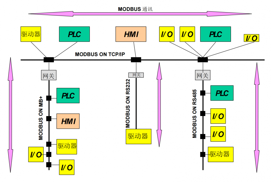
Modbus protocolLiterally, it includesModandBusTwo parts, firstly it is abusBus protocol, similar to I2C and SPI, means that there is a master and a slave on the same bus.

Modbus supports single master, multiple slaves, and up to 247 slave devices. AboutModBecause this protocol was first used in PLC controllers, to be preciseModiconThe company's PLC controller, which is alsoMod-BusThe origin of the name.
Later, Modicon was acquired by Schneider, and the Modbus protocol was widely used in industrial controllers, HMIs, and sensors. It gradually became accepted by other manufacturers and became a mainstream communication protocol for communicating with peripheral devices.
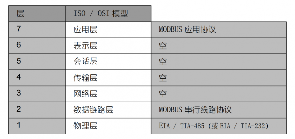
Modbus in7-layer OSI reference modelThe middle layer belongs to the seventh application layer, and there are two types of data link layers: based on standard serial port protocol and TCP protocol, the physical layer can use 3-wire 232, 2-wire 485, 4-wire 422, or various transmission media such as fiber optic, Ethernet, wireless, etc.
Modbus protocol is a type of protocolRequest/ResponseThe interaction process of the method involves the host initiating a communication request, and the slave responding to the host's request. When the slave does not receive the host's request, it will not actively send data, and there will be no communication between the slaves.
Just like boys chasing girls, boys need to take the initiative and girls will respond to you, you can't wait for girls to initiate a conversation with you.
Currently more authoritativeOfficial Modbus Standard DocumentThere are two:
- modbus_application_protocol_specification_v1.1b3.pdf
- Industrial Automation Network Specification GB-T19582.1-2008 based on Modbus Protocol. pdf
It can be said that 90% of books and online resources are translated from these two documents,Method for downloading standard documents at the end of the article.
4 types of data
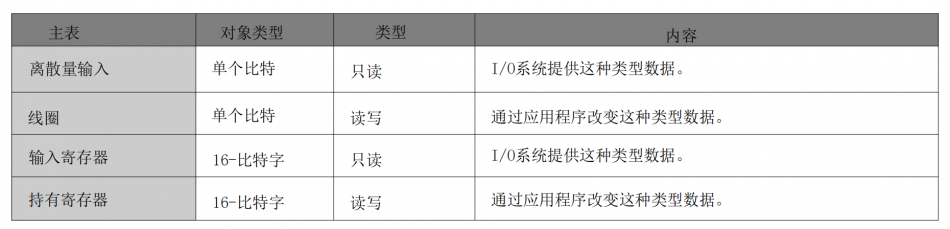
According to the Modbus protocol, the data types for read and write operations can be classified into the following four types based on their read and write properties and types:
- Discretes Input: 1-bit, read-only
- Coil: 1 bit, read-write
- Input registers: 16 bits, read-only
- Holding registers: 16 bits, read-write
3 transmission modes
In 1979, Modicon first introduced the serial Modbus standard. Later, due to the popularity of networks and the need for higher transmission speeds, the Modbus standard based on TCP networks was developed in 1997.
So it can be generally divided into two transmission modes: based onSerial linkAnd based onEthernet TCP/IPof But personally, I still prefer to divide it into three transmission modes:
- Modbus RTU based on serial portThe data is encoded according to the standard serial protocol, which is the most widely used Modbus protocol and uses the CRC-16-MModbus verification algorithm.
- Modbus ASCII based on serial portAll data is in ASCII format, and one byte of raw data requires two characters to represent, which is inefficient. LRC verification algorithm is used.
- Modbus TCP based on Ethernet portModbus TCP is based on TCP/IP protocol and occupiesPort 502The data frame mainly consists of two parts: MBAP (message header)+PDU (frame structure), and the data block is consistent with the serial link.
So when we mention the Modbus protocol, we need to determine which mode it is: RTU, ASCII, or TCP, and the difference between the three modes is still significant.

Some devices support multiple Modbus modes, while others only support one. For example, the most commonly used PLC S7-200 only supports Modbus RTU protocol and does not support Modbus ASCII protocol. All devices on the Modbus busThe transmission mode must be the same.
The actual use should be based on the device manual to choose which mode to use.
3 types of function codes
Modbus function codes are written in the host request data frame, determining whether the host performs read or write operations, whether to read coils, discrete quantities or registers, whether to write a single register or multiple registers, and so on, determining what type of data the host requests.
It mainly includes three types of function codes:Public function code, user-defined function code, and reserved function code
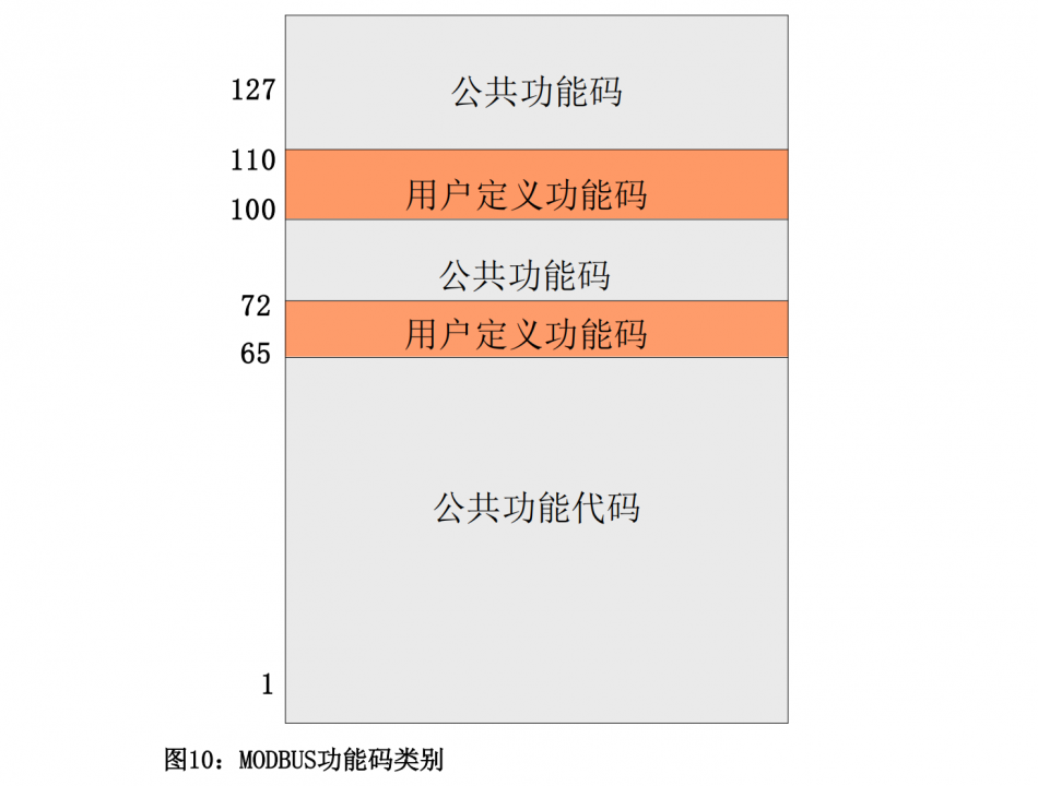
The most commonly used in practice are the four function codes in the public function code: 03/04/06/10
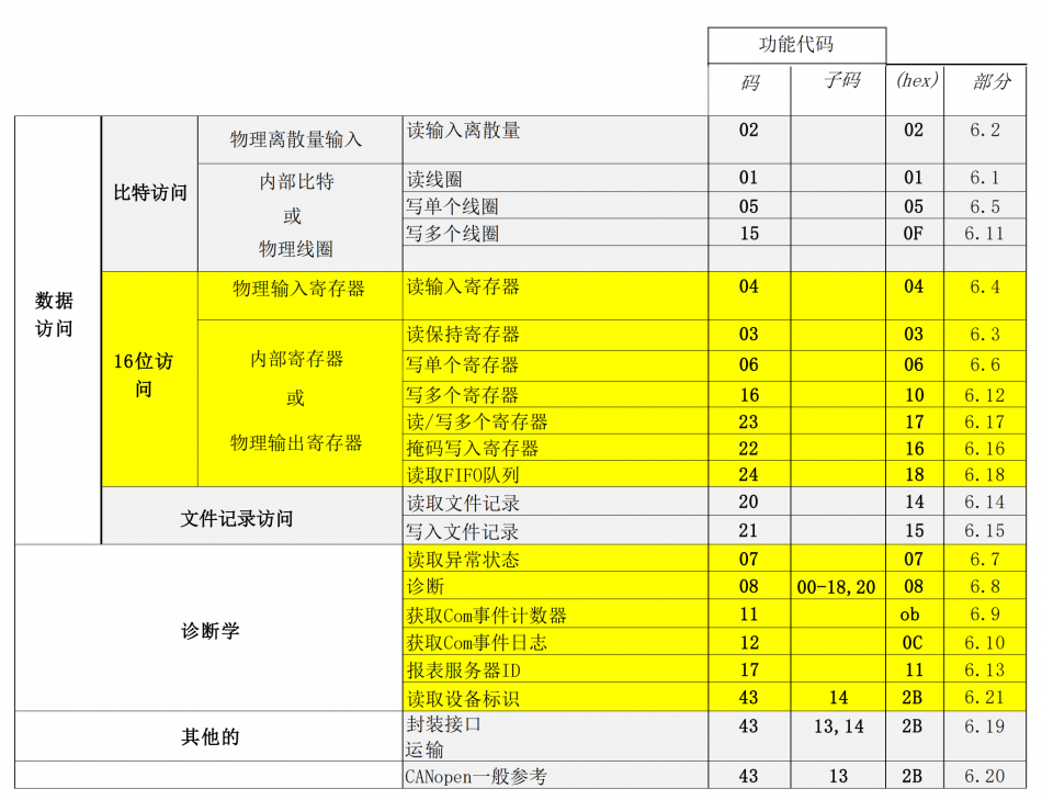
- 0x03: Read multiple hold registers
- 0x04: Read input register
- 0x06: Write a single hold register
- 0x10: Write multiple hold registers
Because PLC mainly controls relay contacts, coils are often read and written on the PLC.
It needs hereSpecial attentionOne point is that when writing to a hold register, it is necessary to distinguish between writing to a single register at 0x06 and writing to multiple registers at 0x10, while reading to a hold register does not distinguish between reading to a single register and reading to multiple registers. When reading to a single hold register, the 0x03 instruction is also used, specifying a read quantity of 1.
data frame format
Regardless of which of the three transmission modes is used, the Modbus frame format remains the same:

Mainly includes:
- Address field: 1 byte, which is the address of the slave device. Usually 1-247 is the valid address, and 0 is the broadcast address
- Function code: 1 byte, indicating the type of data requested by the host.
- Data: N bytes, including register addresses and register data, etc.
- Error checking: The result of redundancy checking on data, CRC or LRC
Below, we will provide a detailed introduction to the data frame format for each transmission mode.
Modbus RTU data frame
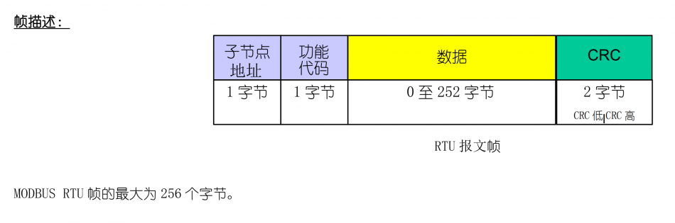
Modbus RTU data frame, with a maximum frame length of 256 bytes, consists of the following four parts:
- Child node address: 1 byte, range 0-247
- Function code: 1 byte
- Data block: 0-252 bytes
- CRC check value: 2 bytes, with the lower 8 bits at the beginning
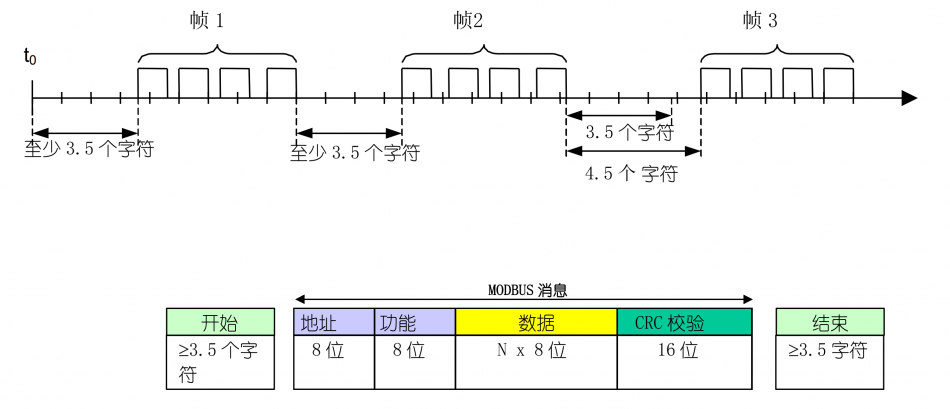
Modbus RTU frame interval, Modbus RTU requires that the frame interval between two RTU messages be greater than 3.5 bytes of time:
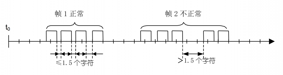
And the byte interval within each message frame is less than 1.5 byte times, otherwise it will be considered incomplete reception.
Modbus RTU uses the cyclic redundancy checking (CRC) algorithm to calculate all data in the message frame, and the resulting check value is attached to the end of the message frame, with the lower bits at the beginning. The calculation method for CRC-16Modbus can refer to the CRC-16Modbus verification algorithm
Example of actual request/response interaction:
Example 1Write a single register. Write 1 data to the register of device 0x0105 at address 01: 0x0190
Host sends: 01 06 01 05 01 90 99 CB
Reply from the machine: 01 06 01 05 01 90 99 CB
01 represents the slave address, 06 function code represents writing to a single hold register, 0105 represents the register address, 0190 represents the value written to the register, and 99CB is the CRC check value. It can be seen that when writing data to one register, the data frame responded by the slave and the data frame sent by the host are consistent.
Example 2Write multiple registers. Write data to three registers at addresses 0x0105, 0x0106, and 0x0107 of device 01: 0x1102, 0x0304, and 0x0566
Host sends:01 10 01 05 00 03 06 11 02 03 04 05 66 4a 12
Reply from the machine:01 10 01 05 00 03 91 f5
Similarly, 01 slave address, 10 function code represents writing multiple hold registers, 0105 represents starting address, 0003 represents writing 3 registers, 06 represents data size of 6 bytes, 1102/0304/0566 represent values written to 3 registers, and 4a12 represents CRC check values.
It can be seen that using 10 function codes when writing multiple registers also simplifies the data recovery from the slave.
Example 3Read a single register. Read 01 address device 0x0105 to hold register data.
Host sends:01 03 01 05 00 01 95 f7
Reply from the machine:01 03 02 56 78 87 c6
03 represents reading multiple registers, 0105 represents starting address, 0001 represents reading one register
02 represents 2 bytes, 56 78 represents the data in the register.
Example 4Read multiple registers. Read the address holding registers of devices 0x0105, 0x0106, and 0x0107, totaling 3 register data.
Host sends:01 03 01 05 00 03 14 36
Reply from the machine:01 03 06 11 22 33 44 55 66 2a 18
03 represents reading multiple registers, 0105 represents starting address, 0003 represents reading 3 registers
06 represents 6 bytes, and 11 22 33 44 55 66 represents the data in the register.
Modbus ASCII data frame
In Modbus ASCII transmission mode, each byte is encoded in ASCII, and in actual messages, one byte is sent as two ASCII characters. Therefore, this mode is less efficient than Modbus RTU mode.
For example, message data0x5B = "5" + "B" = 0X35 + 0X42.
The data frame format is as follows:

From the ASCII message frame, it can be seen that the ASCII mode has added frame start (":") and frame end flags (carriage return&line break). Since each byte of the message data requires 2 characters to be encoded in ASCII mode, in order to ensure compatibility between ASCII mode and RTU mode at the application level, the maximum length of the ASCII mode data block is 252x2. Therefore, the maximum length of the message frame can be calculated as 1+2+2+2x252+2+2=513 characters, and the character interval time within the message frame can reach 1 second.
The Modbus ASCII mode verification method usesVertical redundancy checkThe Long Longitudinal Redundancy Checking (LRC) algorithm does not include the start and end characters of a frame.
The calculation method is also relatively simple, accumulating and calculating the verification content, ignoring carry, and converting it into binary complement:
For example, in Modbus ASCII mode, the host sends a request to the 0x405 address of the slave device with address 1, writing the value 0x1234. The message is as follows:
:010604051234AA<CR><LF>
Namely:
: 01 06 04 05 12 34 AA <CR><LF>
It can be seen that 01 represents the device address, and 06 represents writing a single hold register. The address is 0x0405, the data is 0x1234, and the LRC checksum is 0xAA. The actual data being verified does not include the frame header and footer.
0xAA = LRC(01, 06, 04, 05, 12, 34).
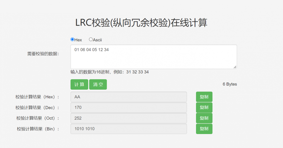
Manual LRC calculation method:
Combine two characters of the original data into one byte and perform binary addition calculation: 01+06+04+05+12+34=0x56, calculate the binary complement:
0x56 = 0101 0110
  negate:1010 1001
  Add 1: 1010 1010 = 0xAA
or:0x100-0x56 = 0xAA
Modbus TCP data frame
Modbus TCP is based on four types of messages:
- MODBUS request is a message sent by the client on the network to initiate transaction processing
- MODBUS confirms that the response information is received at the client end
- MODBUS indication is a request message received by the server
- MODBUS response is a response message sent by the server
Modbus TCP message frame:
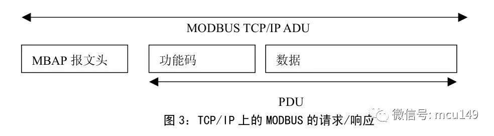
More details can be found in the national standardGB-T19582.1-2008 Part 3: Implementation Guide for Modbus Protocol on TCP/IPView.
Two request modes
In the Modbus protocol, the master can make requests to slave devices in two modes: unicast and broadcast.
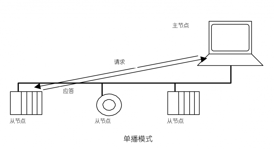
Unicast Mode
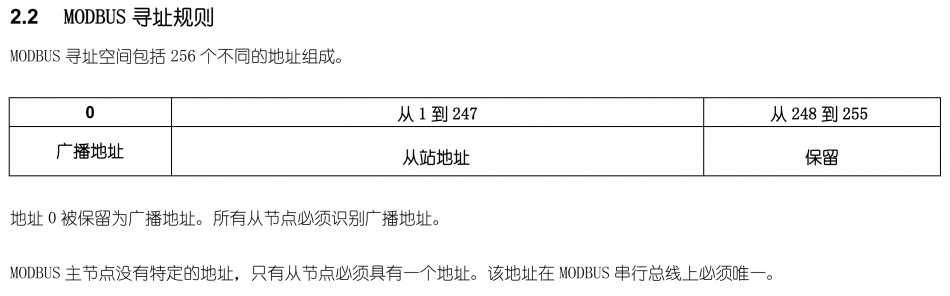
In unicast mode, the slave address must be unique, with an address range of 1-247. The host accesses a specified slave at a specific address and sends a request data frame. The function of this data frame can be to read or write data. After the slave receives and processes it, it will report a response data frame to indicate successful reading or writing.
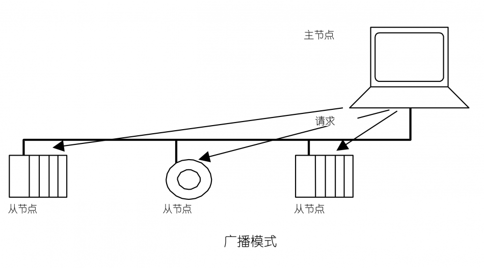
broadcast mode
In broadcast mode, the host sends a request data frame to all slaves, and all slaves process this command. For broadcast requests, all slaves do not need to respond. The general address 0 represents the broadcast address.
But there are also some special devices that use 0xFE as the broadcast address. Taking a gas sensor data manual as an example, 0xFE is used as the broadcast address to modify the device address:

So the user manual of the actual equipment should be used as the standard.
Modbus Address Rules
Modbus Extended Version
Modbus uses asynchronous transmission, which is slow and has its limitations in application. Especially when two PLCs need to exchange data with each other, the amount of data transmitted is large, and asynchronous transmission can no longer meet the overall system response time requirements. So Modbus Plus emerged, using synchronous transmission technology with the same data format as Modbus. This protocol is proprietary to Modicon and different from Modbus, it requires a dedicated coprocessor to handle high-speed token rotation similar to HDLC. It uses 1Mbit/s twisted pair cables and each node has a conversion isolation device, which is a device that uses edge triggering instead of level triggering. Connecting Modbus Plus to a computer requires a special interface, typically a board that supports ISA (SA85), PCI, or PCMCIA bus.
Official standard document download
At present, there are two authoritative standard documents:
- Modbus organization released in April 2012:modbus_application_protocol_specification_v1.1b3.pdf
- national standardIndustrial Automation Network Specification GB-T19582.1-2008 based on Modbus Protocol. pdfIt mainly includes three parts
- GB-T19582.1-2008 Part 1: Modbus Application Protocol
- GB-T19582.1-2008 Part 2: Implementation Guide for Modbus Protocol on Serial Link
- GB-T19582.1-2008 Part 3: Implementation Guide for Modbus Protocol on TCP/IP


Leave a Reply