
1, What is the difference between ModBus RTU communication protocol and ModBus communication protocol?
The ModBus protocol is an application layer message transmission protocol (OSI model layer 7) that defines a protocol data unit (PDU) that is independent of the communication layer, i.e. PDU=function code+data domain.
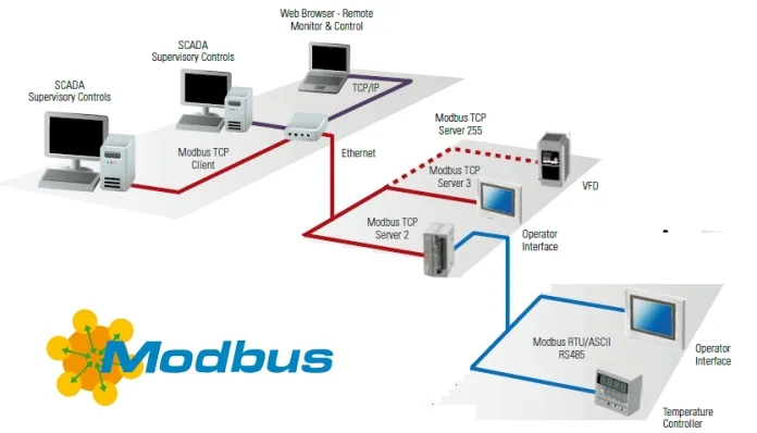
The ModBus protocol can be applied to different types of buses or networks. Corresponding to different buses or networks, the Modbus protocol introduces some additional domains mapped into Application Data Units (ADUs), i.e. ADUs=Additional Fields+PDUs. At present, Modbus has the following three communication methods:
1. Ethernet, corresponding to the communication mode MODBUS TCP.
2. Asynchronous serial transmission (various media such as wired RS-232-/422/485/; The corresponding communication mode for fiber optic, wireless, etc. is MODBUS RTU or MODBUS ASCII.
3. The high-speed token passing network corresponds to Modbus PLUS communication mode.
2, Questions about MODBUS RTU communication protocol?
Modbus mainly consists of a station address (one byte), function code (one byte), first address (two bytes), access word count (two bytes), and checksum (CRC16 or LRC two bytes), totaling 8 bytes. In fact, programming in VB is very simple, just add MSComm components from the assembly, the difficult part is verification,
3, What are Modbus, RTU, and Modbus RTU?
The Modbus protocol is a standard protocol in the industrial control industry, formerly written by Modicon and now acquired by Schneider.
Modbus is divided into two protocols: serial port protocol (Modbus RTU) and network port protocol (Modbus TCP). Generally, industrial computers only support RS232 or RS485 serial port mode. At this time, the protocol stack of industrial computers only has Modbus RTU protocol. When it receives data from the serial port, it will directly control it based on the data in the message. If Modbus TCP protocol is needed for transmission, a PLC with a network port needs to be used.
The specific frame format is as follows:
Modbus RTU Address Field Function Code Data Error Check
Modbus TCP Destination Address Protocol ID Length Unit Number Function Code Data
Simply put, TCP is processed by RTU, while RTU is another concept that is not included in the Modbus protocol and is the abbreviation for monitoring equipment in the industrial control industry.
4, Some issues regarding commands sent by the modbus_STU protocol host
01 Read coil status
02 Read input status of the input coil
03 Read holding register
04 Read input register
05 Writing a Force Single Coil
06 Write a single register (Preset single register)
Write 15 Force multiple coils
16 Write multiple registers (Preset multiple registers)
What do these mean
Answer: 01 Read the status of the logic coil group
02 Read the status of the discrete coil group
03 Read binary values from one or more hold registers
04 Read binary values from one or more input registers
05 Change the state of the logic coil
06 Change the binary value of a single register
15. Change the binary values of multiple registers
16 specifies binary values for multiple operation registers
5, I now have an OPC server with many tags, which come from AB, but how do I connect the tags to Modbus RTU?
Profibus, Fielbus, Modbus, CC link, and so on are communication protocols supported by various PLC hardware. This is the same hardware attribute among manufacturers. However, computer configuration software now supports PLCs with many protocols. You have misunderstood.
Profibus, Fielbus, Modbus, CC link, and other protocols are communication protocols that generally do not require programming, just like when using a computer, you do not need to write IP protocols, you just need to follow them.
The meaning of following is that you must set up the hardware according to the communication protocol supported by the manufacturer when configuring the PLC or DCS hardware. In fact, this is very simple. Here, it simply means that when you learn programming, the focus is on writing programs that execute control actions, and the hardware communication protocol does not require you to write it yourself.
6, What is Modbus RTU Master?
It is to choose RTU mode because MODBUS is divided into ASCII mode and RTU mode. MASER is set as the master station, usually the PLC end, and the frequency converter is set as the slave station. It is also important to pay attention to the setting of the master and slave station addresses.
7, Why doesn't Modbus rtu have start and end markers?
Due to the fact that each byte of a Modbus Rtu frame is a hexadecimal number with a value range of 00~FF, using 02 and 03 to represent start and end markers like Modbus ASCII would conflict with values 2 and 3, making it impossible to determine whether they are markers or values and prevent data unpacking.
8, Conversion from Modbus TCP to RTU?
Please carefully review the frame format:
ModbusRTU Address Field Function Code Data Error Check
ModbusTCP Destination Address Protocol ID Length Unit Number Function Code Data
Write a TCP to RTU program and put it in the device to create a Modbus bridge
9, Is the MODBUS RTU communication line burnt?
Measure the communication line with a multimeter. The voltage should not exceed 5V, and it should not burn anything. When connecting, distinguish between positive and negative. Many products B are positive, take a measurement and see.
10, How to set up touch screen Modbus RTU?
Generally, it is implemented through macro instructions programmed by oneself, but there are also those that support RTU, which can be found in the communication type menu
11, How are floating-point numbers stored in the MODBUS RTU protocol, and how are the values read from the floating-point register converted into the required floating-point numbers?
The byte format for floating-point numbers is as follows:
Address+0+1+2+3
Content SEEE EEEE EMMM MMMM MMMM MMMM MMMM MMMM
Here S represents the sign bit, 1 is negative, 0 is positive
E offset to the power of 127, binary order code=(EEEEEEEE) -127.
The tail of M24 bits is stored in 23 bits, with only 23 bits stored and the highest bit fixed at 1. This method achieves a higher effective number of bits with the minimum number of bits, improving accuracy. Zero is a specific value, with powers equal to 0 and tails equal to 0.
The floating point number -12.5 is saved as a hexadecimal number 0xC1480000 in the storage area, and this value is as follows:
Address+0+1+2+3
Content 0xC1 0x48 0x00 0x00 0x00
The conversion between floating-point numbers and hexadecimal equivalent stored values is quite simple. The following example illustrates how to convert the value -12.5 above. Floating point value saving is not a direct format. To convert to a floating point number, the bits must be saved according to the floating point number saving format table above
Separate as listed, for example:
Address+0+1+2+3
Format SEEE EEEE EMMM MMMM MMMM MMMM MMMM MMMM
Binary 11000001 01001000 00000000 00000000
Hexadecimal C1 48 00 00
The following information can be obtained from this example:
The sign bit is 1, indicating that a negative power is binary 10000010 or decimal 130130 minus 127, which is 3, which is the actual power. The last digit is the following binary number 10010000000000000000
To the left of the tail, there is an omitted decimal point and 1, which is often omitted in floating-point storage. Adding a 1 and the decimal point to the beginning of the tail gives the following tail value:
1.10010000000000000000000
Next, adjust the tail according to the index A negative index moves the decimal point to the left A positive index moves the decimal point to the right Because the index is 3, the tail adjustment is as follows:
1100.10000000000000000000
The result is a binary floating-point number, with the binary number to the left of the decimal point representing a power of 2 at the position, for example: 1100 represents
(1 * 2 ^ 3)+(1 * 2 ^ 2)+(0 * 2 ^ 1)+(0 * 2 ^ 0)=12.
The right side of the decimal point also represents the power of 2 at the position, but the power is negative. For example:. 100... represents (1 * 2 ^ (-1))+(0 * 2 ^ (-2))+(0 * 2 ^ (-2)) ..=0.5.
The sum of these values is 12.5. Because the set symbol indicates that the number is negative, the hexadecimal value 0xC1480000 represents -12.5.
12, RS-485 devices comply with the MODBUS-RTU protocol. How to use a computer to read information?
Using a computer's serial port, connect a 485 converter to the device's 485 interface, and then find a serial software to send a Modbus message based on the register address on the device data. The Modbus message is sent through the serial software in the format of 01 03 00 00 01 840A Read Register Command.
13, How to write VB Modbus to send data to ModScan32 RTU?
Determine which software is the master and which is the slave. Then determine whether the communication protocol is RTU, ASCII, or TCP. If it is TCP, use socket control. RTU ASCII uses COM controls. Then send and receive the corresponding port according to the protocol and parse it.
14, What is the difference between ModBus RTU communication protocol and ModBus communication protocol?
The Modbus protocol includes MODBUS RTU
15, How to determine timeout in Modbus RTU communication protocol?
Set a flag to indicate whether it has timed out; Use another timer with a duration of 3.5 characters to send (of course, for safety reasons, it can be longer); Set a timeout flag in the timer; When a byte is received during a serial interrupt, the timer is reset to zero; In the main program, corresponding processing is performed based on the timeout flag.
16, How to understand the 1.5 and 3.5 character intervals in MODBUS protocol RTU mode?
There should be a certain time interval between sending two frames of data to ensure that the receiving UART can distinguish between them. This time interval is required to be 1.5 and 3.5 character intervals in MODBUS RTU mode, which is the time for transmitting 1.5 and 3.5 characters. It depends on the set communication parameters and is calculated as:
If the serial communication parameters are set to (note: the start bit is fixed at 1): data bit 8, parity bit 1, stop bit 1, baud rate 9600bps, then the time to transmit one character (i.e. one byte) is: (1+8+1+1)/9600=0.00114583s=1.154583ms
1.5 character interval=1.5x1.1454583ms=1.71818745ms
3.5 character interval=3.5x1.1454583ms=4.00910405ms
17, MODBUS RTU testing software?
Recommendation: modscan32
18, MODBUS RTU protocol, communication between the upper computer and the instrument, reading and writing data are correct. Why is the instrument powered off and the written parameters lost? How to save?
Two possibilities:
If the parameters set on the instrument cannot be saved after power failure, it can be basically determined that it is an instrument problem;
2. Some instruments need to write confirmation parameters to fixed registers after writing parameters. To ensure the accuracy of the written parameters, it is necessary to check the instrument communication manual.


Leave a Reply