
Source: Modbus Chinese Network (modbus. cn) - a leading Modbus communication protocol technology community in China
This article: Complete Modbus RS-485 Wiring Manual: From Cable Selection to Debugging and Running Through · Author: Modbus Technical Team · Released on July 1, 2026
Summary: RS-485 wiring is the first hurdle for Modbus communication, which has blocked countless beginners - not because the principle is difficult, but because there are too many details and low fault tolerance. This article covers the entire process from A/B line identification, topology structure, wire selection, shielding layer grounding, terminal resistance and bias resistance configuration, lightning protection to debugging and troubleshooting. Each suggestion comes from on-site accidents, and each parameter can be directly applied to construction. Keywords: RS-485 wiring, Modbus wiring, terminal resistance, bias resistance, shielding grounding, handle topology.
The most common scene on site: the equipment is installed, the parameters are matched, the program is written, and when powered on, the communication light does not flash. Measure the A/B line with a multimeter, and the voltage keeps jumping between 0.3V and 1.8V, without even reaching the differential swing of 5V. Check the wiring again - A and B are connected in reverse. Half an hour of work has turned into three hours of on-site investigation.
RS-485 wiring is like this quirky honest person: the rules are actually very simple, but if you don't follow them, they will definitely not talk nonsense to you.
1, Understanding RS-485 signal lines: which one is A and which one is B
RS-485 communication relies solely on two differential signal lines - traditionally labeled as A (or D -) and B (or D+). The meaning of differential transmission is not to rely on the absolute voltage value of a single wire to transmit data, but to compare the voltage difference between wires A and B.
When the voltage of line B is higher than the voltage of line A by more than 200mV (i.e. B-A>+200mV), it indicates logic 1. When the voltage of line A is higher than the voltage of line B by more than 200mV (i.e. B-A<-200mV), it indicates logic 0. If the voltage difference between A and B is within ± 200mV, this is an uncertain state - the receiving end does not know whether it is 1 or 0, and may read random noise.
That's why you must confirm that A and B are not reversed - after reversing, the logic 1 on the sending end becomes logic 0 on the receiving end, and every byte of the Modbus frame is completely scrambled.
1.1 Manufacturer's A/B standards: Not every manufacturer labels "A" and "B"
This is the most tricky part of RS-485 wiring - different manufacturers define A and B in reverse. Some are labeled as' A=positive electrode (B+), B=negative electrode (A -) ', while others are labeled as' A=D -, B=D+'. Moreover, the Modbus specification itself does not mandate the naming convention of A/B, it only specifies the electrical characteristics of differential signals.
So if the manual you have in your hand is in English, it may be labeled as D+, D -, Tx+, Tx -. If it is a domestically produced instrument, it may be labeled as A, B, GND. How to confirm? Use a multimeter.
1.2 The ultimate method for determining A/B lines using a multimeter
When the device is powered on but idle (without communication), use a multimeter to measure the voltage of A to GND and B to GND in the DC voltage range.
In idle state (without data transmission), the default state of the bus is maintained by a bias resistor: the voltage on line B should be higher than that on line A. Typical values: B is about 2.5V~3.5V to ground, and A is about 1.5V~2.5V to ground.
If it is measured that A is higher than B, then the definitions of A and B are exactly the opposite of the device you are trying, and they can be interchanged to make it work.
There is also an on-site quick judgment method: first connect all devices' A to A, B to B, and GND to GND. After powering on, use a multimeter to measure the voltage between A-B in the AC voltage range. If communication is normal, you will see significant voltage fluctuations (ranging from a few hundred millivolts to a few volts) during data transmission. If there is no fluctuation, either the terminal resistor is not connected, causing the bus to float, or the A/B connection is reversed, causing all slave stations to simultaneously believe that an error frame has been received.
2, Topology: Can only hold hands and reject all branches
2.1 Correct topology
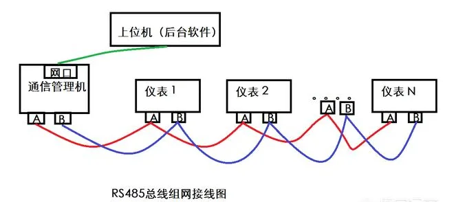
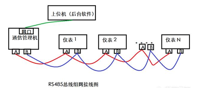
The RS-485 bus must adopt a "hand in hand" daisy chain topology - from one device, only connect to the next device, without branching:
host ─── [Device 1] ─── [Device 2] ─── [Device 3] ─── ... ─── [DeviceN]
  │           │           │           │                   │
  └─ 120Ω ────┘           │           │                   │
                    Continue to connect in sequence          └───────── 120Ω ──┘
                                             (Terminal resistance at the end)
Connect a 120 Ω terminal resistor at each end of the bus, and connect the intermediate devices in series sequentially.
2.2 Absolutely Prohibited Connection Methods
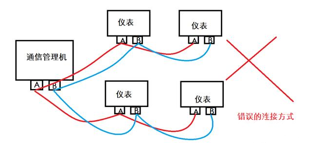
Star ConnectionAll devices radiate from the same centralized point.
        ┌── [Device 1]
host ──[node]── [Device 2]
        └── [Device 3]
Tree branchSplit a branch from the middle of the bus to hang the device.
2.3 Unnecessary branch measures on site
If the physical location of the on-site devices is indeed impossible to handle hand in hand (such as a row of devices installed on one wall and another wall with devices), do not force a star configuration - use an RS-485 distributor (also known as a hub) to divide the backbone into multiple independent network segments, and each network segment will still have a standard handle topology. The RS-485 distributor is essentially a multi port repeater, with independent driver and receiver circuits for each port, replacing simple copper wire branches.
3, Cable selection: If one cable is selected incorrectly, all cables will be lost
3.1 Shielded twisted pair cable (RVSP) must be used
RS-485 relies on differential signals to suppress common mode interference - the induced voltage of the interference signal on lines A and B is almost the same, and it naturally cancels out when the receiver performs differential subtraction. Twisted pair cables can ensure that the interference coupling between A and B wires is as similar as possible. The more uniform the twisting distance and the tighter the twisting, the better the anti-interference effect.
| Cable Type | Is it available? | reason |
|---|---|---|
| RVSP (shielded twisted pair cable, characteristic impedance 120 Ω) | best choice | Specially designed for RS-485 |
| RVV (ordinary sheath parallel line) | Unavailable | Not twisted pair, interference coupling is unbalanced |
| Ethernet cable (Cat5e/6 UTP) | Not recommended | Although it is a twisted pair cable, the characteristic impedance is 100 Ω and there is no overall shielding |
| coaxial cable | Unavailable | Single ended signal is completely different from differential signal |
| Ordinary BV wire (single core hard wire) | Unavailable | No twisted pair, no differential, equivalent to two antennas |
Wire diameter requirement: 0.75mm ² or 1.0mm ² (approximately AWG18-20). 0.5mm ² can only run in ideal environments within 300 meters, and 0.75mm ² or more must be used for long-distance or strong interference sites.
Characteristic impedance requirement: 120 Ω. This matches your terminal resistance of 120 Ω, and cannot be replaced with a 100 Ω Ethernet cable casually - impedance mismatch means that signals will be reflected at every transition point of the cable.
3.2 Common Wild Roads on Site
Split one Ethernet cable into two cores to use as a 485 cable "- The Ethernet cable is UTP (unshielded), and the 8-core cable has four pairs of twisted pairs inside. You only use one pair, and the remaining 6 cores are floating as 6 antennas, which introduces a huge imbalance to the interference coupling of twisted pair cables. If youmustUse Ethernet cables (there are only Ethernet cables on site), use a knife to cut off all the unused 6-core cables and stick them to the ground, leaving only the pair you are using, and then ground the shielding layer of these 2-core cables. This is stronger than using Ethernet directly, but still inferior to regular RVSP.
Tie the 485 signal line and 220V power supply together and thread them through the same tube "- the electromagnetic interference excited by the PWM waveform on the primary side of the inverter on the power supply line can directly flip the 200mV threshold of the 485 differential signal. The 485 line must maintain a parallel distance of at least 30cm from the strong current (power line, frequency converter output line), and must be crossed at a right angle when crossing.
4, Shielding layer grounding: single point or double point?
RS-485 uses low-frequency differential signals (with a typical baud rate of only 115.2kbps), which belong to low-frequency circuits. The basic principles of low-frequency circuits:Single-point grounding.
4.1 Rule: Single point grounding of shielding layer
The shielding layer is only grounded at one end of the bus. The other end is suspended and not connected to anything.
Why? If both ends are grounded, a loop current (ground loop) will be generated in the shielding layer due to the different grounding resistances of the two grounds. This current flowing on the shielding layer itself is an interference source - it not only does not shield, but also couples noise to the signal line. Single point grounding severed this loop.
4.2 To which end?
Prioritize grounding on the main station side (PLC, upper computer, gateway side). Reason: The main station usually has better grounding conditions (standard distribution cabinets, equipotential grounding bars), while the on-site equipment side has poor grounding conditions (the equipment casing is connected to an unknown grounding pile).
If the main station side itself is a floating ground system (the equipment does not have a grounding terminal), the shielding layer can be connected to the lightning protection grounding bar on the on-site equipment side. The key is: only connect one end.
What to do if it exceeds 50 meters
If the bus length exceeds 50 meters and the on-site electromagnetic environment is particularly harsh (with a frequency converter or high-power motor nearby), single point grounding may not be sufficient - the effectiveness of single point grounding will be attenuated if the shielding layer is too long. At this time, adoptDouble ended grounding+series resistanceThe far end of the shielding layer is not directly grounded, but is grounded through a 100 Ω~1k Ω resistor. The resistance limits the current in the ground loop while maintaining the potential difference between the two ends of the shielding layer.
4.4 Connection of Signal Ground (GND)
Many RS-485 devices have GND (signal ground) terminals in addition to A and B lines. Do I need to connect this GND?
If all devices are on the same power system (DC 24V from the same distribution cabinet), GND can be omitted - the GND of each device is already equipotential.
If the device uses an independent power supply (each with a switch power adapter), the GND terminals of all devices must be connected in series (note: GND is connected in series, not grounded). There may be a common mode voltage difference of several volts or even tens of volts between the GND of different power sources - if this difference exceeds the common mode range of the 485 transceiver (typically -7V~+12V), the transceiver will burn out or never recognize the signal. The function of the GND line is to pull the reference ground of all devices to the same potential.
5, Terminal resistance: two positions of 120 Ω
5.1 Function of Terminal Resistance
The behavior of signals on transmission lines is similar to that of water waves in pipelines. When the pipeline suddenly reaches its end, water waves will bounce back. The characteristic impedance of RS-485 twisted pair cable is about 120 Ω. If the signal suddenly encounters high impedance (open circuit) at the end of the line, there will be no energy consumption and it will be reflected back. The reflected wave is superimposed on the original signal, forming ringing and overshoot.
Terminal resistors are connected at both ends of the bus with a 120 Ω resistor across lines A and B, so that the impedance at the end of the cable is equal to 120 Ω - consistent with the characteristic impedance of the cable. When the signal reaches the end, it is absorbed by the resistor without reflection.
5.2 Where to connect
Connect only one device at each end of the bus. The intermediate device is not connected. If three or more terminal resistors are connected, the total parallel resistance will be lower than 120 Ω, which will instead increase the load on the 485 driver and lower the signal amplitude.
5.3 Under what circumstances should we consider not connecting terminal resistors
Short distance (<50 meters), low baud rate (≤ 9600), with only 2-3 devices. At this time, the energy reflected by the signal is extremely small, and it can work normally without connecting the terminal resistor. But this needs to be confirmed through actual testing - there will be no side effects if connected, it is a safe practice.
Terminal resistance is required for baud rates above 38400 or distances exceeding 100 meters.
6, Bias resistor: prevents noise during idle time
6.1 Background of the problem
When the RS-485 bus is idle (with no devices sending data), the status of lines A and B is uncertain. If the bus is completely floating at this time (only the terminal resistor pulls A and B together), any small electromagnetic noise may cause voltage fluctuations of more than ± 200mV between A-B - what the receiving end sees is an unsolicited random byte. This phenomenon is called 'idle noise triggering communication interruption', which is manifested as the master station sending a query but the slave station not responding - because the interrupt service program of the slave station is occupied by idle random bytes on the CPU.
6.2 Principle of bias resistor
Add a pull-up resistor (A to+3.3V/5V) and a pull-down resistor (B to GND) to one end of the bus, so that the voltage on line B is automatically higher than line A by more than 200mV when idle - the bus defaults to a certain logic 1 state (idle state). This group of resistors is called Fail safe Bias Resistors.
6.3 Calculation Method
The standard 485 bus has two 120 Ω terminal resistors (connected to both ends). After adding a bias resistor, the equivalent circuit of the terminal connection becomes: pull-up resistor Rpu connected to 5V → 120 Ω terminal resistor → pull-down resistor Rpd connected to GND.
Require B-A ≥ 200mV when idle, calculate:
Rpu=Rpd=680 Ω, power supply 5V——
When idle, the voltage at point A is 5V × (680 Ω//half of the lower 120 Ω)/(680 Ω+680 Ω//R)
Simplified formula: Rpu=Rpd ≈ 5V/(V_AB_min/Rterm)=5/(0.2/60) ≈ 1.5k Ω - this calculation is too ideal. In practical engineering, using 680 Ω or 560 Ω directly is sufficient. Common solution: Rpu=Rpd=680 Ω, connected at one end of the bus.
The following table shows the idle voltage of commonly used bias resistor values under 5V power supply:
| Bias resistance value (Rpu=Rpd) | Idle B-A voltage (approximately) | Applicable scenarios |
|---|---|---|
| 1.5kΩ | 200mV | Critical value, clean and usable environment |
| 1kΩ | 300mV | General recommendation |
| 680Ω | 430mV | An environment with slight interference |
| 560Ω | 530mV | The bottom line of strong interference but not too small |
| 470Ω | 640mV | Strong interference, but even if it's small, it will pull the power supply |
The bias resistor should not be too small - too small will lower the effective signal amplitude of the 485 driver and waste too much bias current.
Many RS-485 serial port cards and converters (such as USB to RS-485 modules) on the market already have built-in bias resistors on the circuit board. In this case, there is no need to apply bias to the far end of the bus - butTo confirmUse a multimeter to cut off power and measure the resistance values of A to VCC and B to GND. If the range of 680 Ω~1.5k Ω is measured, it indicates that there is a built-in bias.
7, Lightning protection and overvoltage protection
As long as the RS-485 communication line goes out of a building and runs between two buildings, surge protection must be considered. The voltage resistance of RS-485 transceivers is usually around ± 12V~± 15V. A close range lightning strike induction can bring an instantaneous voltage of several hundred volts to several thousand volts - directly burning out the transceiver chip.
7.1 Level 3 Protection Plan
The standard three-level RS-485 surge protection is:
Level 1Connect a gas discharge tube (GDT) to the protective earth (PE) of lines A and B, with a voltage resistance of 90V~150V, to discharge amplified energy.
Level 2Connect a TVS transient suppression diode (such as SMBJ6.5CA, with a breakdown voltage of 6.5V) to PE on both A and B lines, and clamp the residual voltage.
Level 3Connect a PTC self recovery fuse (such as 50mA-100mA level) in series with lines A and B to limit the continuous current.
In this three-level scheme, GDT consumes the maximum energy, TVS consumes the remaining peak, and PTC limits the continuous current. In actual deployment, an RS-485 lightning protection module can be installed at the entrance of the bus (at the pipe penetration point on the exterior wall of the building), and the signal can be connected to indoor equipment through normal wiring.
7.2 Lightning protection grounding must be reliable
The grounding terminal of lightning protection devices must be connected to the grounding bar with low impedance. The grounding resistance of the lightning protection grounding bar should be ≤ 4 Ω. If the lightning protection device introduces surge current into an unqualified ground, the surge current passing through the high impedance of the ground will instantly raise the entire 'ground potential', and then send the surge back to the communication chip through common ground coupling, which is equivalent to no protection.
8, Debugging process: from multimeter to running through
Sorting in this order is the most effective:
Step 1: Power off inspection
All devices are powered off. Measure the DC resistance between A-B using a multimeter in the resistance range. If the terminal resistor is connected to 120 Ω, it should be between 60 Ω and 120 Ω (depending on the input impedance of other devices). If the resistor is in an open circuit state, either the wire is broken or the terminal resistor is not connected.
Measure the resistance of A to ground and B to ground - it should be high resistance (several tens of k Ω or more). If a short circuit or low resistance is detected, the cable may be damaged or the device port may be punctured.
Step 2: Power on and check the idle voltage
All devices are powered on, but the main station does not send data (or unplugges the main station). Measure with a multimeter in DC voltage range:
- A to GND: should be around 1.5V~2.5V
- B to GND: should be around 2.5V~3.5V
- A-B voltage: B should be higher than A, with a difference of about 200mV~600mV
If the A-B voltage is close to 0V or extremely low (B voltage), it is likely that the bias resistor is reversed or A/B is reversed at the device end.
Step 3: Single Slave Communication Test
Add the slave stations on the bus one by one. First, only connect to slave station 01, and the master station sends a command to read and hold the register (function code 03, read one register). There is a response → The wiring and parameters of this machine are correct. No response → Check the matching of slave address, baud rate, data bit/stop bit/checksum.
Many beginners think that the default address for the device is 1, 9600, 8N1- but different manufacturers have different defaults. Some default to 1, while others default to 247. The baud rate may be any one of 4800, 9600, 19200, 115200. The checksum may be no checksum (N), even checksum (E), or odd checksum (O). The manual states' default 9600, 8N1 ', but during factory testing, the engineer may have changed it to 19200- there is no shortcut to this type of pit, only checking and synchronizing parameters one by one against the manual.
Step 4: Joint debugging of all equipment
After a single machine runs smoothly, add the next one. Add one and test one. Don't hang up all the devices at once and look for problems - RS-485 failures are often caused by one device failing and dragging down the entire bus, but if all sixteen devices are hung up, you don't even know who did it.
If there is a sudden communication problem after adding it to a certain device, unplug it first to see if the bus is restored. Recovery → This device has issues (port damage, baud rate mismatch, address conflict). Do not restore → Check the wiring, terminal resistance, and power supply of the previous units.
Step 5: Use an oscilloscope to observe the waveform
If the multimeter does not detect the problem but still has communication issues, the oscilloscope is the ultimate weapon. Connect the oscilloscope probe (preferably a differential probe, if not available, use two single ended probes for A-B calculations) across the A/B line and trigger the main station to send a Modbus command frame.
A normal waveform should show that B is higher than A (logic 1) when idle. Clear square wave appears at the beginning of transmission - low level (BA) It is logic 1. The rising/falling edge of the square wave should be clean and sharp, without obvious overshoot or ringing. The frame gap (3.5 character time) is a clear idle high-level area on the oscilloscope.
If you see severe ringing (multiple wavy lines at the top of the square wave), the terminal resistance selection is incorrect or not connected. If the voltage keeps shaking during idle time and the amplitude exceeds ± 200mV, the bias is insufficient or the cable shielding is not grounded. If the A-B voltage is always much lower than normal (such as a swing of only 1V instead of 3-5V), the driver load is too heavy (too many terminal resistors are connected in parallel, the number of devices exceeds the chip's driving capacity, or one device port is damaged).
9, Quick troubleshooting of common faults
| phenomenon | The most likely reason | inspection method |
|---|---|---|
| All devices are not communicating | A/B line reversed, bus open circuit, no bias | Measure idle voltage and resistance |
| One path is normal, another path is abnormal | Abnormal device baud rate/address/checksum mismatch | Single unit testing |
| Communication is intermittent | Terminal resistor missing or poor contact, bus too long | Oscilloscope to observe ringing |
| Occasionally receiving garbled text | Shielding ungrounded, near strong interference sources, insufficient bias | Test environment, check shielding |
| Global failure after adding new device | New device port damage or A/B short circuit | Isolate one by one |
| Received random data during idle time | Lack of bias resistor | Measure idle voltage and apply bias |
| Normal when baud rate is low, not possible when baud rate is high | Poor cable quality or distance exceeding the limit | Reduce baud rate or switch cables |
10, Construction Inspection Checklist
After the wiring is completed, check each item one by one:
- The topology is a hand in hand daisy chain without stars or branches
- [] Connect a 120 Ω terminal resistor at each end of the bus
- The cable is shielded twisted pair (RVSP) with a diameter of ≥ 0.75mm ²
- [] Unnecessary network cable cores have been processed (will not float as antennas)
- The distance between the 485 line and the strong current is ≥ 30cm, and it passes vertically when crossing
- [] Single point grounding of shielding layer (priority for main station side)
- All GND lines of non common source devices have been connected in series
- If passing through outdoors, a lightning protection module has been installed and reliably grounded
- [] The bias resistor has been configured at a point on the bus (or confirmed to be built-in in the converter)
- All devices have A connected to A, B connected to B, and GND connected to GND
- [] The baud rate/address/checksum of each device has been verified and recorded
- [] Can run smoothly at a single point, can run smoothly at all points
Each item on this list is a lesson learned by industrial control engineers who paid a price on site. Wiring does not rely on intuition or luck - it relies on step-by-step verification.
Let's talk if there are any issues.


Leave a Reply