
1. Version Information
- Product Category: 60GHz Human Occupancy Sensor (RS485 Version)
- Product Model: MSA300D 485
- Product Version: V1.0
2. Model Description
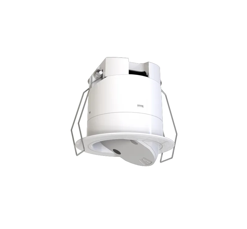
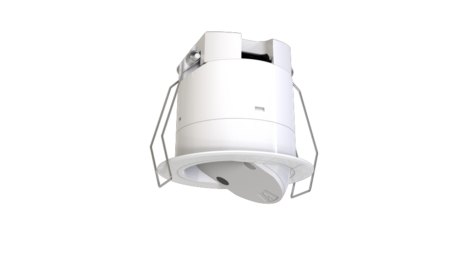
MSA300D 485 is a 60GHz radar sensor based on multi array high gain. Its induction antenna can achieve infinite adjustment from -30 ° to 30 °, achieving precise coverage of target scenes with the induction antenna. At the same time, its antenna gain is high and the induction beam angle is narrow, making it particularly suitable for detecting human presence information in extremely small areas, such as workstation/toilet detection. Combined with unique software algorithms, it can accurately detect the occupancy status of people at workstations/toilets, providing fast and accurate front-end sensing inputs for current human based smart offices and smart bathrooms.
Product Purchase:https://www.modbus.cn/product/31216.html
III. Product Features
- Live breathing presence static detection
- Accurate output of human/unmanned signals
- Accurate detection of human presence information in a very small range
- Supports RS485 wired communication
- Supports induction antenna -30 ° to 30 ° adjustment
- Uses 60GHz millimeter wave radar technology
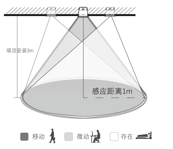
- Presence perception maximum range: diameter 1-3 meters
- Micro motion perception maximum range: diameter 1-3 meters
- Movement perception maximum range: diameter 1-3 meters
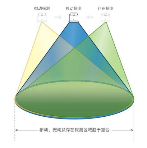
- Respiratory presence, micro motion perception, movement perception range highly overlapping
- Circular radiation pattern, effectively achieving spatial detection coverage of workstations/toilets
- No one to someone State switching time: within 0.5 seconds
- Switching time from manned to unmanned state: greater than 10 seconds
- Support ceiling embedded installation
- Set induction parameters through RS485 protocol
- Ultra low RF power output, harmless to human health
- Not affected by temperature, humidity, noise, airflow, dust, light and other environmental factors
4, Appearance characteristics
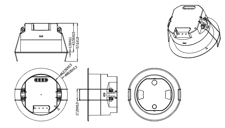
- Size: φ80×43.5mm
- interface4-digit shrapnel lifting terminal
5, Parameter characteristics
(1) Input/Output
- voltage range: 12-24V DC
- Rated voltage: 12V/24V DC
- operating current: 300mA max
- Working power consumption: ≤1W @24V DC
- Communication method: RS485
(2) Induction parameters
- RF operating frequency: 60GHz-64GHz
- transmit power: 5mW Max
- Detection AreaCan be set to 0% -100% through RS485 protocol
- Delay setting (Hold Time)Can be set to 1s-7200s through RS485 protocol
- Range of ambient light measurement5-1200Lux (the product is installed at a height of 3m and the illuminance value of the ground directly below the product is collected)
(3) Detection range (100% sensitivity, radius)
- Mobile/Micro motion/Presence (3m high): 0.5-1.5m
(IV) Other Parameters
- Remote Control Function: Supports
- Installation Height: 2-3.5m
- 3dB Beam Angle:
- XZ Plane: 30 °
- YZ Plane: 30 °
(V) Operating Environment
- Embedded Installation Hole Size: Φ 70mm
- Working Environment Temperature: 0 ℃~+50 ℃
- Storage temperature: -25 ℃~+80 ℃
(VI) Certification standard
- Compliant with certification: FCC/RED
- Environmental requirements: Compliant with EU RoHS requirements
- Protection level: IP20
6, Size and Function Diagram
[There should be size and functional diagrams here]
7. Wiring Diagram and Wiring Suggestions
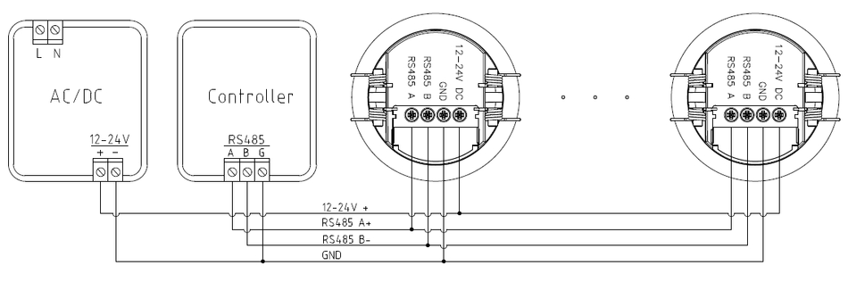
(1) Wiring Suggestions
- RS485 Wiring Method: It is recommended to hold hands and wire one line to the end, and it is not recommended to use star or tree wiring to ensure signal transmission stability
- RS485 Wiring Material: It is recommended to use a 0.5 square meter 4-core shielded wire or a 6-class network wire. The length of the bus wiring should not exceed 300 meters, and the number of sensors connected to a bus should not exceed 12
- This sensor does not have terminal resistors. When connecting to the bus system, please pay attention to impedance matching. Generally, it is recommended to use two 120 ohm resistors as the terminal matching resistors for the 485 bus
8. Startup process and initialization
The indicator light flashes for 10 seconds before turning off. During initialization, no external movement sensing signals are detected. The indicator light can be used through RS485 Turn off and on the indicator light, and the delay time and detection range (sensing distance) can be set through RS485
. 9. Factory settings
- Detection Area: 100%
- Hold Time: 30s
- Indicator light: open
10, Induction radiation pattern
The typical installation recommendation for the MSA300D 485 millimeter wave radar sensor is a ceiling mounted installation. The radiation range during ceiling mounted installation is as follows:
11, Signal detection instructions
This millimeter wave radar sensor detects human movement, micro movements, and presence signals, achieving the detection of human presence (with or without people) during sleep. The specific instructions are as follows:
- Mobile signalDetected significant movement (walking) signals of the human body within the detection area.
- Micro motion signal: Detected small amplitude motion signals of the human body within the detection area, such as forward leaning, backward leaning, limb swinging, shaking head, typing, playing with mobile phones, and other small amplitude behavioral movements.
- Presence signal: Detected respiratory vital signs of the human body (abdominal and thoracic dilation behavior), but did not detect large movement signals or micro motion signals.
Section 12: Communication Parameter Format and Protocol
(1) Basic Parameters
- Baud Rate for Serial Communication: 9600
- Data Bits: 8
- Stop Bits: 1
(2) Data Frame Format
- DATA0: Frame Header
- DATA1: ID High Bit
- DATA2: ID Low Bit
- DATA3: Length
- DATA4: Function
- DATA5/DATA6/DATA7: Value (if DATA7 is not available, DATA6 is the checksum); If there is no DATA8, DATA7 is the checksum)
- DATA8: checksum
(3) Communication data requirements
- Communication Data Type: HEX Format Sending and Receiving
- Each setting command interval should be greater than 150ms, and the return data should be monitored to see if it is the same as the sending. If it is not received, it should be resent no more than 3 times
(IV) Example
Example 1
| Project | Frame Header | ID High Bit | ID Low Bit | Length | Function | Value | Checksum |
|---|---|---|---|---|---|---|---|
| DATA0 | DATA1 | DATA2 | DATA3 | DATA4 | DATA5 | DATA6 | DATA7 |
| 51 | FF | FF | 06 | 05 | 64 | BE | |
| Checksum calculation: 51+FF+FF+06+05+64=2BE, take the last two digits BE |
Example 2
| Project | Frame header | ID high bit | ID low bit | Length | Function | Value | Checksum |
|---|---|---|---|---|---|---|---|
| DATA0 | DATA1 | DATA2 | DATA3 | DATA4 | DATA5 | DATA6 | DATA7 |
| 51 | FF | FF | 08 | 07 | 09 | 27 | C0 |
| Checksum Calculation: 51+FF+FF+08+07+09+27+C0=34E, take the last two 4E |
Thirteen, Merrytek Microwave Sensor Standard Communication Command Function Correspondence Table
| DATA4 Command | Function Name | Data Range | Read/Write | Default Value |
|---|---|---|---|---|
| 0x00 | Read Function Data | w | w | |
| 0x03 | Work State | 1-2 | w/r | |
| 0x05 | Detection Area | 0-4 | w/r | 4 |
| 0x07 | Blocking Time | 0-FFFFFF | w | 0 |
| 0x08 | LED Indicator | 0-1 | w/r | 1 |
| 0x09 | Light Sensor | 0-800lux | r | |
| 0x0A | Difference Value | 10-100 | w/r | 10Lux |
| 0x0D | Delay Time Hold Time | 2-7200 | w/r | 30s |
| 0x17 | Firmware Version | 0.0.0-100.0.0 | r | Current Version Number |
| 0x18 | Device Address Device ID | 0x0000-0xFFFF | w/r | 0xFFFF |
| 0x20 | Illuminance multiplier value Daylight Level Compensation (multiple) | 0x01-0x64 | w/r | 0xA |
| 0x21 | Edit ID | 0-1 | w | 0x00 |
| 0x22 | Report/Query Switch Submit a report/Inquiry about | 0-1 | w/r | 1 |
| 0x23 | Flip status filmp | 1 | w | 1 |
| 0x25 | Light sensing threshold: Daylight sensor | 0-800lux, 65535 | w/r | 65535 |
| 0x26 | Sensor enable Mition detection on/off | 0-1 | w/r | 0 |
| 0x28 | Presence detection on/off | 0-1 | w/r | 1 |
| 0X29 | Set installation height setting | 0-2 | w/r | 2 |
(1) Command operation instructions
1. Read functional data
This function is generally used to query sensor parameters and will return corresponding function data based on the function command number.
| Numerical Function | HEAD (DATA0) | ID (DATA1-DATA2) | LEN (DATA3) | Format (DATA4) | Function (DATA5) | CRC (DATA6) |
|---|---|---|---|---|---|---|
| Query Work Status | 0x51 | 0xFF | 0x06 | 0x00 | 0x03 | data0+…+data5 |
| Query the sensing range | 0x51 | 0xFFFF | 0x06 | 0x00 | 0x05 | data0+…+data5 |
| Query LED status | 0x51 | 0xFFFF | 0x06 | 0x00 | 0x08 | data0+…+data5 |
| Query the illuminance value | 0x51 | 0xFFFF | 0x06 | 0x00 | 0x09 | data0+…+data5 |
| Query the difference in illuminance | 0x51 | 0xFFFF | 0x06 | 0x00 | 0x0A | data0+…+data5 |
| Query delay time | 0x51 | 0xFFFF | 0x06 | 0x00 | 0x0D | data0+…+data5 |
| Query firmware version | 0x51 | 0xFF | 0x06 | 0x00 | 0x17 | data0+...+data5 |
| Query device address | 0x51 | 0xFFFF | 0x06 | 0x00 | 0x18 | data0+…+data5 |
| Check if it is allowed to actively report | 0x51 | 0xFFFF | 0x06 | 0x00 | 0x22 | data0+...+data5 |
| Query Light Sensing Threshold | 0x51 | 0xFF | 0x06 | 0x00 | 0x25 | data0+...+data5 |
| Query Sensor Enable | 0x51 | 0xFF | 0x06 | 0x00 | 0x26 | data0+…+data5 |
| Query existence detection enable | 0x51 | 0xFFFF | 0x06 | 0x00 | 0x28 | data0+…+data5 |
| Query installation height | 0x51 | 0xFFFF | 0x06 | 0x00 | 0x29 | data0+…+data5 |
2. Working Status
This function automatically reports the working status of the sensor.
| Numerical Function | HEAD (DATA0) | ID (DATA1-DATA2) | LEN (DATA3) | Function (DATA4) | Value (DATA5) | CRC (DATA6) |
|---|---|---|---|---|---|---|
| Unmanned state | 0x51 | 0xFFFF | 0x06 | 0x03 | 0x01 | data0+…+data5 |
| Someone's status | 0x51 | 0xFFFF | 0x06 | 0x03 | 0x02 | data0+…+data5 |
Status reporting instructions:
- When switching from unmanned state to manned state, report immediately.
- Do not report duplicate status of someone (work status can be queried).
3. Sensing Range
This function can set the detection range of the sensor and adjust the corresponding gear according to the size of the space.
| Numerical function | HEAD (DATA0) | ID (DATA1-DATA2) | LEN (DATA3) | Function (DATA4) | Value (DATA5) | CRC (DATA6) |
|---|---|---|---|---|---|---|
| Min:1 | 0x51 | 0xFFFF | 0x06 | 0x05 | 0x01 | data0+…+data5 |
| Max:4 | 0x51 | 0xFFFF | 0x06 | 0x05 | 0x04 | data0+…+data5 |
4. LED Indicator light
This function can set the LED indicator light to turn on or off.
| Numerical function | HEAD (DATA0) | ID (DATA1-DATA2) | LEN (DATA3) | Functio (DATA4) | Value (DATA5) | CRC (DATA6) |
|---|---|---|---|---|---|---|
| Disable | 0x51 | 0xFFFF | 0x06 | 0x08 | 0x00 | data0+…+data5 |
| Enable | 0x51 | 0xFFFF | 0x06 | 0x08 | 0x01 | data0+…+data5 |
5. Blocking time
Block Sensor, This function can set the sensor blocking time, with a minimum time unit of 1 second. During the blocking time, the sensor will not output any triggering status or mode, and will automatically allow the sensor to trigger after the set time countdown is completed.
| Numerical function | HEAD (DATA0) | ID (DATA1-DATA2) | LEN (DATA3) | Function (DATA4) | Value (DATA5-DATA7) | CRC (DATA8) |
|---|---|---|---|---|---|---|
| Min: 1s | 0x51 | 0xFFFF | 0x08 | 0x07 | 0x000001 | data0+…+data7 |
| Max: 167772125s | 0x51 | 0xFFFF | 0x08 | 0x07 | 0xFFFFFF | data0+...+data7 |
6. Illuminance Value
This function can obtain the current ambient illuminance value, and when the change in ambient illuminance meets the preset illuminance difference, the sensor immediately reports the ambient illuminance value.
| Numerical function | HEAD (DATA0) | ID (DATA1-DATA2) | LEN (DATA3) | Function (DATA4) | Value (DATA5-DATA6) | CRC (DATA7) |
|---|---|---|---|---|---|---|
| Min: 0Lux | 0x51 | 0xFFFF | 0x07 | 0x09 | 0x0000 | data0+…+data6 |
| Max: 800Lux | 0x51 | 0xFFFF | 0x07 | 0x09 | 0x0320 | data0+…+data6 |
7. Delay time
This function can set a delay time for the sensor to enter the unmanned delay time. It is recommended to set the application time to 30 seconds to 3 minutes.
| Numerical function | HEAD (DATA0) | ID (DATA1-DATA2) | LEN (DATA3) | Function (DATA4) | Value (DATA5-DATA6) | CRC (DATA7) |
|---|---|---|---|---|---|---|
| Min: 2s | 0x51 | 0xFFFF | 0x07 | 0x0D | 0x0002 | data0+…+data6 |
| Max: 7200s | 0x51 | 0xFFFF | 0x07 | 0x0D | 0x1C20 | data0+…+data6 |
8. Firmware Version
This feature allows you to view the firmware version number of the sensor.
| Numerical function | HEAD (DATA0) | ID (DATA1-DATA2) | LEN (DATA3) | Function (DATA4) | Value (DATA5- DATA6) | CRC (DATA7) |
|---|---|---|---|---|---|---|
| Min:v0.0.0 | 0x51 | 0xFFFF | 0x07 | 0x17 | 0x0000 | data0+…+data6 |
| Max:v100.0.0 | 0x51 | 0xFFFF | 0x07 | 0x17 | 0x2710 | data0+…+data6 |
9. Device ID
This function allows setting the device ID address to distinguish the unique ID of the sensor device.
| Numerical function | HEAD (DATA0) | ID (DATA1-DATA2) | LEN (DATA3) | Function (DATA4) | Value (DATA5-DATA6) | CRC (DATA7) |
|---|---|---|---|---|---|---|
| Min:0x0000 | 0x51 | 0xFFFF | 0x07 | 0x18 | 0x0000 | data0+…+data6 |
| Max:0xFFFF | 0x51 | 0xFFFF | 0x07 | 0x18 | 0xFFFF | data0+…+data6 |
Related instructions:
- Edit ID method: After 20 seconds of power on self-test, press the button briefly once to enter ID programming mode (51 FF FF 06 21 01 77 appears on the serial port), the indicator light will flash quickly, and the ID can be set within one minute. After successful completion, the indicator light will stop flashing. (After entering, press the button briefly again to exit the programming mode, and the indicator light will stop flashing)
- Device ID default value: 0xFFFF
- Method for restoring factory settingsPress and hold the button for 3 seconds to restore the factory settings. The device ID will not be restored, and active reporting and passive querying will not be restored.
- Factory settings parameters: Installation height of 3m, sensitivity: 4th gear, delay time: 30s, indicator light: on.
- Note: On a 485 bus, only one sensor can be in edit ID mode! Cannot be done simultaneously to avoid address errors!
10. Light sensitivity difference
refers to the set value of the change in ambient light intensity value, which immediately reports the light intensity value when the change in ambient light intensity value exceeds the set value.
| Numerical function | HEAD (DATA0) | ID (DATA1- DATA2) | LEN (DATA3) | Function (DATA4) | Value (DATA5) | CRC (DATA6) |
|---|---|---|---|---|---|---|
| Min: 10Lux | 0x51 | 0xFFFF | 0x06 | 0x0A | 0x0A | data0+…+data5 |
| Max: 100Lux | 0x51 | 0xFFFF | 0x06 | 0x0A | 0x64 | data0+…+data5 |
11. Light sensitivity compensation coefficient
sets the multiple of light sensitivity value, used for calibrating the numerical function of light sensitivity value
| Numerical function | HEAD (DATA0) | ID (DATA1-DATA2) | LEN (DATA3) | Function (DATA4) | Value (DATA5) | CRC (DATA6) |
|---|---|---|---|---|---|---|
| Min:0x01 | 0x51 | 0xFFFF | 0x06 | 0x20 | 0x01 | data0+…+data5 |
| Max:0x64 | 0x51 | 0xFFFF | 0x06 | 0x20 | 0x64 | data0+…+data5 |
12. ID The editing status
is used to check if the ID allows editing. 0: Cannot be changed, 1: Can be changed
| Numerical function | HEAD (DATA0) | ID (DATA1-DATA2) | LEN (DATA3) | Function (DATA4) | Value (DATA5) | CRC (DATA6) |
|---|---|---|---|---|---|---|
| Disable | 0x51 | 0xFFFF | 0x06 | 0x21 | 0x00 | data0+…+data5 |
| Enable | 0x51 | 0xFFFF | 0x06 | 0x21 | 0x01 | data0+…+data5 |
13. Report/Query Switching
Used to set whether to actively report. 00: Query mode 01: Proactive reporting
| Numerical function | HEAD (DATA0) | ID (DATA1-DATA2) | LEN (DATA3) | Function (DATA4) | Value (DATA5) | CRC (DATA6) |
|---|---|---|---|---|---|---|
| Disable | 0x51 | 0xFFFF | 0x06 | 0x22 | 0x00 | data0+…+data5 |
| Enable | 0x51 | 0xFFFF | 0x06 | 0x22 | 0x01 | data0+…+data5 |
14. Flip State
is used for flipping states. When the sensor is in a manned state and receives an instruction, it switches states and replies to 'unmanned'. When the sensor is in an unmanned state and receives an instruction, it switches states and replies to 'manned'.
| Numerical Function | HEAD (DATA0) | ID (DATA1-DATA2) | LEN (DATA3) | Function (DATA4) | Value (DATA5) | CRC (DATA6) |
|---|---|---|---|---|---|---|
| Enable | 0x51 | 0xFF | 0x06 | 0x23 | 0x01 | data0+...+data5 |
15. Light sensing threshold
If the Lux value detected by the device is lower than this value, sensing is allowed. If the Lux value detected is greater than this value after entering the unmanned state of the device, sensing is prohibited; When the light sensing threshold is 0xFFFF, the Lux value, which is the command (0x09), will be reported;
| Numerical Function | HEAD (DATA0) | ID (DATA1-DATA2) | LEN (DATA3) | Function (DATA4) | Value (DATA5-DATA6) | CRC (DATA7) |
|---|---|---|---|---|---|---|
| Min: 0Lux | 0x51 | 0xFFFF | 0x07 | 0x25 | 0x0000 | data0+…+data6 |
| Max: 800Lux | 0x51 | 0xFFFF | 0x07 | 0x25 | 0x0320 | data0+...+data6 |
| 65535 (indicating no light sensing threshold function) | 0x51 | 0xFFFF | 0X07 | 0X25 | 0xFFFF | data0+...+data6 |
16. Sensor Enable
If the sensor is enabled, the device prohibits sensing; If the sensor is enabled to turn off, the device will be allowed to sense after 10 seconds.
| Numerical Function | HEAD (DATA0) | ID (DATA1-DATA2) | LEN (DATA3) | Function (DATA4) | Value (DATA5) | CRC (DATA6) |
|---|---|---|---|---|---|---|
| Enable to open | 0x51 | 0xFF | 0x06 | 0x26 | 0x01 | data0+...+data5 |
| enable disable | 0x51 | 0xFF | 0x06 | 0x26 | 0x00 | data0+...+data5 |
17. Presence detection enable
This function can be set to enable or disable the presence detection function 01, enable 00, disable
| numerical function | HEAD (DATA0) | ID (DATA1-DATA2) | LEN (DATA3) | Function (DATA4) | Value (DATA5) | CRC (DATA6) |
|---|---|---|---|---|---|---|
| Enable to open | 0x51 | 0xFF | 0x06 | 0x28 | 0x01 | data0+...+data5 |
| Enable to disable | 0x51 | 0xFF | 0x06 | 0x28 | 0x00 | data0+...+data5 |
18. Set installation height
0x00 corresponds to a height of 220cm, 0x01 corresponds to a height of 260cm, 0x02 corresponds to a height of 300cm
| Numerical function | HEAD (DATA0) | ID (DATA1-DATA2) | LEN (DATA3) | Function (DATA4) | Value (DATA5) | CRC (DATA6) |
|---|---|---|---|---|---|---|
| Set installation height to 220 cm | 0x51 | 0xFFFF | 0x06 | 0x29 | 0x00 | data0+…+data5 |
| Set installation height to 260cm | 0x51 | 0xFFFF | 0x06 | 0x29 | 0x01 | data0+…+data5 |
| Set installation height to 300cm | 0x51 | 0xFFFF | 0x06 | 0x29 | 0x02 | data0+...+data5 |
RemarksIf there is an error in setting the data range, return: 51XXXX06FF02XX; If there are no such features or commands sent incorrectly, there will be no response.
14, Disclaimer
Due to the complexity of product technology and the differences in application environments, it is difficult to guarantee a completely accurate or complete description. Therefore, this information is only for user reference. We reserve the right to make changes to the product specifications without notifying the user, and do not make any legal commitments or guarantees. At the same time, our company encourages users to provide suggestions for supplementing or modifying the content of our specification sheet after trying out our products.


Leave a Reply