
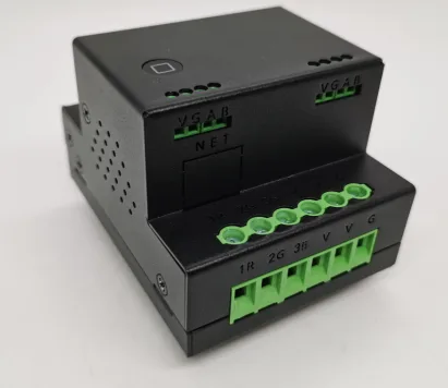
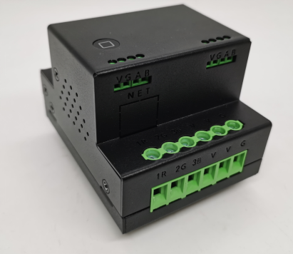
1. Product Overview
M510 is an intelligent dimming module that supports 5-channel 0-10V pure voltage analog signal output, compatible with bus (RS485), WiFi, and Apple Home (HomeKit) control, providing 255 level digital infinite dimming, 25 segment dimming curve, branch group control, and breathing mode functions. An intelligent lighting control system suitable for home, commercial, and industrial scenarios, supporting Modbus industrial control protocol and seamlessly integrated into industrial control systems.
2, Technical parameters
| parameter item | Specification |
|---|---|
| Product Model | M510 |
| input voltage | DC12V |
| output voltage | 0-10V (each independent output) |
| driving capability | ≤ 50mA/channel |
| Communication method | RS485 bus, WiFi (2.4GHz) |
| Industrial control protocol | Modbus |
| Baud rate | 9600 |
| Apple home support | HomeKit direct connection control (metal shell) |
| Installation method | DN35 rail installation |
| Working temperature | -10 ° C~50 ° C |
| Size | 69 *57* 87mm |
| Weight | 0.35kg |
III. Installation and Configuration
1. Hardware Installation
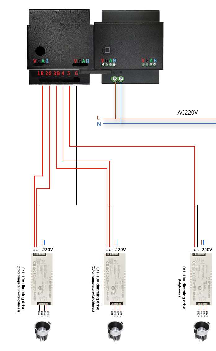
- Power WiringThe input voltage range must meet the optional requirements (DC12V).
- signal outputEach 0-10V interface is connected to a dimming driver.
- communication interfaceThe RS485 bus needs to be connected according to A/B polarity.
2. Indicator light status
| Indicator light behavior | meaning |
|---|---|
| 1S flashing | The device is running normally |
| On for 5 seconds, off for 1 second | Server connection successful |
| extinguish | Enter distribution network mode |
| Chang Liang | Enter HomeKit configuration mode |
4, Detailed Explanation of Protocol Instructions
1. Address Modification Protocol
Function: Modify the unique address of the device (5 bytes).
Instruction format:
[旧地址(5字节)] F8 E7 D6 [新地址(5字节)]
Example:
Old address1A 13 24 56 91Change to new address2A 33 57 26 81:
发送:1A 13 24 56 91 F8 E7 D6 2A 33 57 26 81
反馈:BC BC(操作成功)
2. Group control protocol
Wildcard rule: FFAs a wildcard, it can match any address range (0x00~0xFE).
Instruction Format:
[地址掩码(含FF)] [控制指令]
Example:
- Control all modules:
FF FF FF FF FF [控制指令] - Control address with fixed first 3 bytes and arbitrary last 2 bytes. Module:
XX XX XX FF FF [控制指令]
3. Dimming control protocol
Instruction format:
[地址(5字节)] [路数功能][输出值][状态] ... [结尾符0F]
Parameter description:
- Function code:
00(off),01(on),02(on/off),FF(adjust),03(brighten),04(dim) - Output value:
00(0%) toFF(100%), linearly corresponding to brightness level - Status code:
01(valid),00(invalid),02(adaptive dimming)
Example:
Set the first output to 50% (0x80), the second output to be turned off:
[地址] FF 80 01 FF 00 01 0F 4. Dimming curve configuration protocol
Function: Set 25 dimming time intervals (each segment in 10ms units).
Instruction Format:
[地址(5字节)] BB D2 [路数] [25段间隔值] 0F
Parameter Description:
- Number of Channels:
00(1st channel) to04(5th channel),FF(Full channel) - Interval Value:
01(10ms) toFF(2550ms)
Example:
Setting 25 segment dimming curve for 1st channel:
[地址] BB D2 00 01 11 20 30 ...(25段值) 0F 5. Respiratory Mode Configuration Protocol
Instruction Format:
[地址(5字节)] EE [循环时间][状态] ... 0F
Parameter Description:
- Loop Time:
00(0s) toFF(255 × 45ms=11.475s) - Status:
01(Start),00(Stop)
Example:
Start the First Breathing Mode (34 Second Loop):
[地址] EE 22 01 ... 0F 6. Extreme Speed Scene Protocol
Function: Store/trigger 256 scene configurations.
Instruction Type:
- Set Scene:
[地址] 69 11 96 [场景位置] [5路输出值] 0F - Trigger Scene:
[地址] 69 12 96 [场景位置] 0F - Save Current Value:
[地址] 69 13 96 [场景位置] 0F - Clear Scene:
[地址] 69 14 96 [场景位置] 0F
Example:
Store 5 Output Values of Scene Position 00:
[地址] 69 11 96 00 11 22 33 44 55 0F 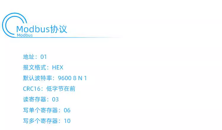
V. Appendix
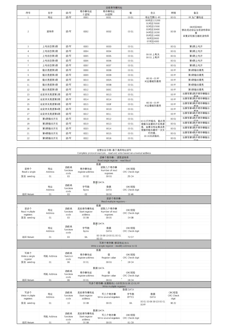
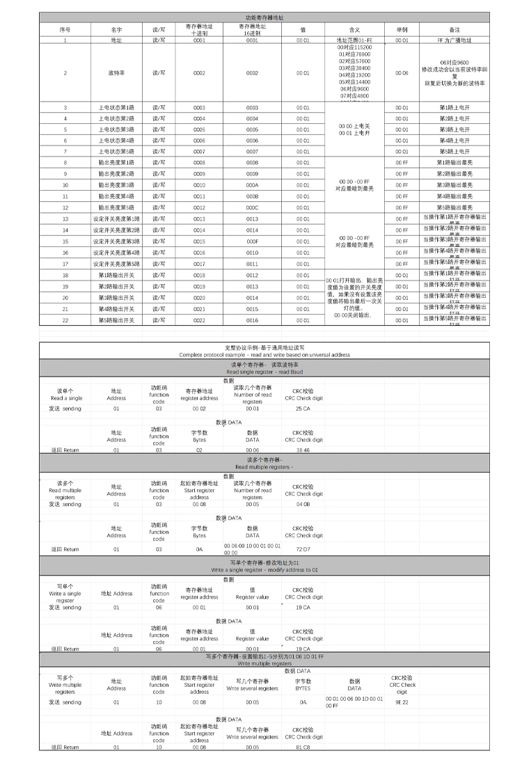
- Modbus Register Mapping Table(see Appendix A for details)
- Fault Code Table(see Appendix B for details)
- Terminology Explanation: HomeKit pairing code, wildcard mask, dimming curve


Leave a Reply