
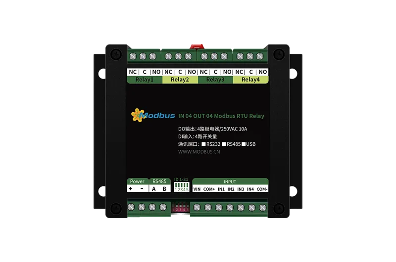
Product Features
30001 to 39999 are input registers (usually analog inputs)
Relay output contact isolation;
Communication baud rate: 2400,4800,9600,19200,38400 (Can be modified through software, Default9600) ;
Communication protocol: Support standardsmodbus RTUagreement;
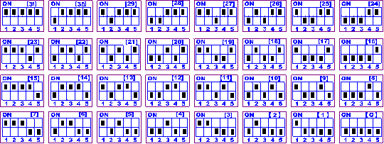
Can be set0-255Device address, 5The address dip switch can be set1-31Address code, Greater than31It can be set up through software;
Capable of flashing, Flashing function, You can include parameters in the instruction, Operate the relay to automatically turn off after a period of time; Equipped with strobe function, Can control the periodic switching of relays.
Product functionality
Four way relay control;
Four channel switch input;
Support manual control through computer software;
Support local non lock linkage mode;
Support local self-locking linkage mode;
Support interlock mode;
Dual machine non lock linkage mode;
Dual machine self-locking linkage mode;
Main parameters
| Parameters | explain |
| Contact capacity | 10A/30VDC 10A/250VAC |
| Durability | 10Ten thousand times |
| Communication interface | RS485 |
| Rated voltage | DC 7-30V |
| Power indicator | 1The road is redLEDinstructions (Always on when not in communication, Flashing during communication) |
| Output indication | 4The road is redLEDinstructions |
| Temperature range | Industrial grade, -40℃~85℃ |
| Size | 115*95*41mm |
| Weight | 330g |
| Default communication format | 9600,n,8,1 |
| Baud rate | 2400,4800,9600,19200,38400 |
| Software support | Supporting configuration software, Control software; Support various configuration software; supportLabviewdWait |
Interface description
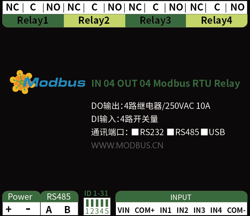
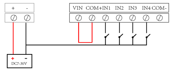
Input/output wiring
1, Relay wiring instructions
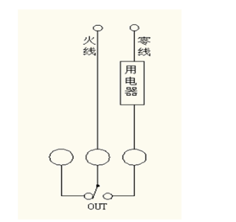
2, Schematic diagram of active switch wiring
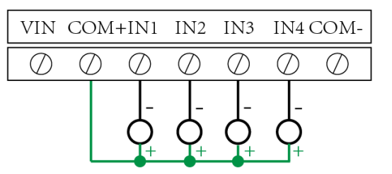
3, Schematic diagram of passive switch wiring

Introduction to the address of the device dip switch
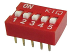
All five dialing codes have been dialed“ON”When in position, For the address“31”;
All five dialing codes have been dialed“OFF”When in position, For the address“0”;
The leftmost 1 is the binary lowest bit.
Address table:
Working mode
Introduction to working mode functions
Non lock linkage mode of this machine
A board module with optocoupler input and relay output, In this mode, The input optocoupler and relay are directly linked. That is: The optocoupler input signal takes effect—>Corresponding relay engagement, The optocoupler input signal is cancelled—>The corresponding relay is disconnected.
Due to mechanical and program delays in this mode, There will be a certain delay in the action of the relay when the optocoupler input signal is received, But the maximum will not exceed0.05Seconds.
Due to the fact that all relays in this mode are directly linked by optocouplers, So there may be a phenomenon where the serial port cannot operate the relay, This is not an abnormal phenomenon, But after operating the relay through the serial port, The status of the optocoupler was linked before the relay was activated.
Local self-locking linkage mode
The module itself is a board module with optocoupler input and relay output, In this mode, The optocoupler inputs a signal every time, Flip the corresponding relay once. That is:
The optocoupler input signal takes effect—>Relay flipping (Pull in and disconnect, Disconnect and switch to suction) ;
The optocoupler input signal is cancelled—>The relay does not operate;
This mode also has the delay problem of non lock mode, But the delay time will also not exceed0.05Seconds.
This mode can mainly be used in situations where external signals are triggered to control the start and stop of equipment, For example, an optocoupler with an external button, Corresponding relay external electrical equipment, Press the button every time, The device will switch between start and stop states once.
Interlocking mode
The module itself is a board module with optocoupler input and relay output, In this mode, The optocoupler inputs a signal every time, The corresponding relay will close, Other optocouplers without input signals will disconnect their corresponding relays. That is:
Optocoupler input signal takes effect—>The corresponding relay is engaged and other relays are disconnected;
The optocoupler input signal is cancelled—>The relay does not operate;
This mode also has the delay problem of non lock mode, But the delay time will also not exceed0.05Seconds.
This mode can mainly be used for external signal triggering to control the start and stop of different devices, For example, if there is no external button connected to a multi-channel optocoupler, Corresponding relay external electrical equipment, Press one button, The corresponding device will switch to the startup state, Other devices will stop running.
Dual machine non lock linkage mode
This mode requires two addresses to be the same, Devices with the same mode completed, Two devices are directly connected485Or cross232After connecting, The optocoupler status of module 1 will directly control the status of the corresponding relay of module 2, That is:
The input signal of optocoupler 1 in module 1 is effective—>The No.1 relay of module 2 is engaged
The input signal of optocoupler 1 in module 1 has disappeared—>The No.1 relay of module 2 is disconnected
The corresponding delay time of the relay in this mode is longer than the previous modes, But it will not be greater than0.1Seconds (9600Baud rate)
If used in this mode485If it is a bus, multiple devices can be connected in parallel, Among them, the addresses of the devices match pairwise, This can achieve remote transmission of switch values. For example: There are multiple low-speed switch values on site that need to be transmitted to500Control the alarm lights or electric bells in the control room located meters away, Then only a few modules need to be arranged in the factory and connected to the corresponding modules in the computer room through two twisted pair shielded wires, You can complete the task. Similarly, the button signals for operating the computer room can also be directly transmitted to the relays located in the computer room module.
Dual machine self-locking linkage mode
This mode requires two addresses to be the same, Devices with the same mode completed, Two devices are directly connected485Or cross232After connecting, The optocoupler status of module 1 will flip the corresponding relay status of control module 2 when it takes effect, That is:
The input signal of optocoupler 1 in module 1 is effective—>The No.1 relay of module 2 is flipped
The input signal of optocoupler 1 in module 1 has disappeared—>The No.1 relay of module 2 does not operate
The application of this mode and“Dual machine non lock linkage”Similar patterns, But it is more suitable for remote control of device start and stop, Simply install a button on the operating end to achieve the action of pressing once to start and once to stop.
Flashing function and settings
Introduction to flashing and disconnecting functions
Manual mode: Operate the relay every time, The relay flips once (Open when closed, Close when disconnected) ;
Flash mode: Operate the relay every time, The relay will close for 1 second (Actual time [in seconds]=set number*0.1) Then disconnect it on its own;
Flash mode: Operate the relay every time, The relay is disconnected1.Seconds (Adjustable time) Close it on its own afterwards;
Flashing and disconnecting settings
The flashing mode cannot be written into the device's interior, It can be achieved by sending instructions, This function can be achieved on the Juying configuration software.
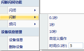
Note:: The flashing mode cannot be written into the device chip, After selecting the flashing and disconnecting mode on the software, All channels are in flash off mode, Single channel control can be achieved by sending a flash off command for a single channel, Does not affect the normal control of other channels.
Development documentation description
Communication protocol description
This product supports standardsmodbusInstructions, Detailed instruction generation and parsing methods, You can refer to the Chinese version of the protocol based on the register table in this articleMODBUSThis product supports both.
Formatmodbus RTU Register description
2, ModbusRegister name
| Function | Register address | explain | Coil control |
| Coil | |||
| Write coils1 | The first relay output | 0x0001 | Coil |
| Write coils2 | Second relay output | 0x0002 | Coil |
| Write coils3 | Third relay output | 0x0003 | Coil |
| Write coils4 | Fourth relay output | 0x0004 | Discrete input |
| Input | |||
| Switching quantity1 | The first input | 1x0001 | Input |
| Switching quantity2 | Second input | 1x0002 | Input |
| Switching quantity3 | Third input | 1x0003 | Third input |
| Input4 | Switching quantity | 1x0004 | Fourth input |
| Configure parameters | |||
| Communication baud rate | Maintain registers | 4x1001 | Refer to the table below for the corresponding baud rate values, The default is0, support0-5 |
| spare | Maintain registers | 4x1002 | spare, Users are not allowed to write any values. |
| Offset address | Maintain registers | 4x1003 | Device address=offset address+dip switch address |
| Working mode | Maintain registers | 4x1004 | Users can use it, Store user data |
| Delay time | Maintain registers | 4x1005 | Users can use it, Store user data |
remarks:
①: ModbusThe device instructions support the following:ModbusAddress:
00001To09999It is a discrete output (Coil)
10001To19999It is a discrete input (Contact point)
30001To39999It is an input register (Usually it is an analog input)
40001To49999It is to maintain registers (Usually storing device configuration information)
Adopting a 5-digit code format, The first character determines the register type, The remaining 4 characters represent the address. Address 1 starts from 0, Like00001corresponding0000.
Table of baud rate values correspondence
| Numerical value | Baud rate |
| 0 | 9600 |
| 1 | 2400 |
| 2 | 4800 |
| 3 | 9600 |
| 4 | 19200 |
| 5 | 38400 |
③: Relay status, Through30002The address can be queried, It can also be done through00001---00002Address inquiry, But control can only be used00001---00002Address.
30002The length of the address data is16bit. Can represent at most16A relay.
The corresponding results are as follows::
| Bit | 15 | 14 | 13 | 12 | 11 | 10 | 9 | 8 | 7 | 6 | 5 | 4 | 3 | 2 | 1 | 0 |
| Relay position | 8 | 7 | 6 | 5 | 4 | 3 | 2 | 1 | 16 | 15 | 14 | 13 | 12 | 11 | 10 | 9 |
Namely registers30009Databit8 And registers00001The data is the same.
Similarly: The same goes for optocoupler input. Register30003of And registersbit8, bit9 All correspond to designated hardware10001, 10002Register address according to.
Naming rulesPLCThe real address is to remove the highest bit, Then subtract one, Instruction list.
explain
| Format | RTUBinary transmission (16Query the status of four channels) |
| Query command returns information | FE 01 00 00 00 04 29 C6 |
| Control the opening of the first route | FE 01 01 00 61 9C |
| Control return information | FE 05 00 00 FF 00 98 35 |
| Control the first pass | FE 05 00 00 FF 00 98 35 |
| Control return information | FE 05 00 00 00 00 D9 C5 |
| Control the opening of the second path | FE 05 00 00 00 00 D9 C5 |
| Control the second pass | FE 05 00 01 FF 00 C9 F5 |
| Control the opening of the third path | FE 05 00 01 00 00 88 05 |
| Control the third pass | FE 05 00 02 FF 00 39 F5 |
| Control the opening of the fourth route | FE 05 00 02 00 00 78 05 |
| Control the fourth pass | FE 05 00 03 FF 00 68 35 |
| Read the first optocoupler | FE 05 00 03 00 00 29 C5 |
| Return information | FE 02 00 00 00 01 AD C5 |
| Read the second optocoupler | FE 02 01 00 91 9C |
| Read the third optocoupler | FE 02 00 01 00 01 FC 05 |
| Read the fourth optocoupler | FE 02 00 02 00 01 0C 05 |
| Instructions | FE 02 00 03 00 01 5D C5 |
Detailed explanationRelay output
Relay inquiry
Road relay (4Send command code)
Fields: FE 01 00 00 00 04 29 C6
| meaning | remarks | Equipment address |
| FE | This is the broadcast address | Instructions |
| 01 | 01Query relay status command | Starting address |
| 00 00 | The first relay register address to be queried | Query quantity |
| 00 04 | The number of relays to be queried | The first 6 bytes of data |
| 29 C6 | CRC16 | ChecksumCRC16Relay card returns information |
Return code:
Fields: FE 01 01 00 61 9C
| meaning | remarks | Device address |
|---|---|---|
| FE | Device address | |
| 01 | 01Instructions | Return instruction: If the query is incorrect, return0x81 |
| 01 | Byte count | Return all bytes of status information. 1+(n-1)/8 |
| 00 | Query status | Return relay status. Bit0:The first relay statusBit1:The second relay status. . . . . . . Bit7:The eighth relay status |
| 61 9C | CRC16 | The first 6 bytes of dataCRC16Checksum |
Optocoupler input
Query optocoupler (4Road optical coupling)
Send command code: FE 02 00 00 00 04 6D C6
| Fields | meaning | remarks |
| FE | Equipment address | |
| 02 | 02Instructions | Query discrete input (Optocoupler input status command |
| 00 00 | Starting address | The register address of the first optocoupler to be queried |
| 00 04 | Query quantity | The number of optocoupler states to be queried |
| 6D C6 | CRC16 | The first 6 bytes of dataCRC16Checksum |
Optocoupler returns information:
Return code: FE 02 01 00 91 9C
| Fields | meaning | remarks |
| FE | Equipment address | |
| 02 | 02Instructions | Return instruction: If the query is incorrect, return0x82 |
| 01 | Byte count | Return all bytes of status information. |
| 00 | Query status | The status of the returned optocoupler. Bit0:The status of the first optocouplerBit1:The status of the second optocoupler. . . . . . . Bit7:The status of the eighth optocoupler |
| 91 9C | CRC16 | The first 6 bytes of dataCRC16Checksum |
Flash open/close command
Analysis of flashing open and close instructions
Flash development code submission: FE 10 00 03 00 02 04 00 04 00 0A 00 D8
Flashing sending code: FE 10 00 03 00 02 04 00 02 00 14 21 62
| Fields | meaning | remarks |
| FE | Equipment address | |
| 10 | 10Instructions | Query input register instruction |
| 00 03 | Relay address | The address of the device to be controlled |
| 00 02 | Control the number of commands | The number of commands required for the relay |
| 04 | Byte count | The total number of bytes for controlling information commands. 1+(n-1)/8 |
| 00 04Or00 02 | Instructions | 00 04To flash the instruction 00 02To execute a flashing command |
| 00 0A | Intermittent time | 00 0ATo convert hexadecimal to decimal is:10The interval time is (0.1Seconds*10) |
| 00 D8 | CRC16 | Verification method |
Return code: FE 10 00 03 00 02 A5 C7
| Fields | meaning | remarks |
| FE | Equipment address | |
| 10 | 10Instructions | Return instruction: If the query is incorrect, return0x82 |
| 00 03 | Equipment address | Query the address of the device |
| 00 02 | Number of received commands | The number of commands received by the device |
| A5 C7 | CRC16 | Checksum |
Fully open and fully close command
Analysis of fully open and fully closed commands
Full development code submission: FE 0F 00 00 00 04 01 FF 31 D2
Completely cut off sending code: FE 0F 00 00 00 04 01 00 71 92
| Fields | meaning | remarks |
| FE | Equipment address | |
| 0F | 0FInstructions | Return instruction: If the query is incorrect, return0x82 |
| 00 00 | Starting address | |
| 00 04 | Control quantity | Number of relays controlled |
| 01 | Byte count | Number of command bytes sent |
| FF (Or00) | Fully open and fully close command | FF Fully open command 00 Full close command |
| 31 D2 (Or71 92) | CRC16 | Checksum |
Complete disconnection and full open return code: FE 0F 00 00 00 04 40 07
| Fields | meaning | remarks |
| FE | Equipment address | |
| 0F | 0FInstructions | Return instruction: If the query is incorrect, Return0x82 |
| 00 00 | Starting address | |
| 00 04 | quantity Number of relays that return information | check digit |
| 40 07 | CRC16 | check digit |


Leave a Reply