
Function Overview
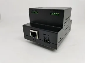
Intelligent control core equipment, receiving various preset instructions, judging through system preset logic, and then outputting various control instructions to control other devices.
Purchase recommendation
Suitable for smart homes, smart buildings, smart exhibition halls, and smart cinemas that require intelligent control, as well as hotels, teahouses, conference rooms, exhibition halls, and business premises that require intelligent control.
Parameters
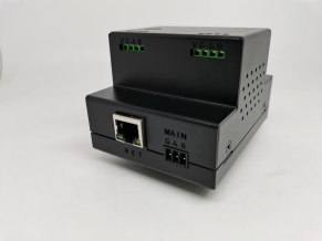
- Product Name: M002 Intelligent Control Host
- Version: V6.1
- Product Model: M002
- Shell Material: Sheet Metal
- Color: Black
- Installation Method: Placement Installation/Standard DN35 Rail
- Size: 69 * 57 * 87mm
- Weight: 350g
- Bus Interface: MQPORT * 2
- Network Interface: RJ45
- Communication: RS485 Bus, Wireless, Network
- Bus: RS485 Type: Isolated 485
- Controlled Baud Rate: 9600
- Controlled Baud Rate: 1200-112200
- Wireless: BT5.0ZGBMESH
- MESH Protocol: Open Customization
- Wired Input: RS485
- Network: TCP/IP
- Network Mode: Server/Client
- Network interaction: Socket
- Clock: RTC
- Independent timing: supported
- Independent Countdown: Supports
- Control Protocol: Custom
- Accused Protocol 1: Open
- Controlled Protocol 2: Custom
- Power supply voltage: 12V
- Power supply current: 2A
- Release time: March 2024
Features
Hardware Design
- Only retain the bus and zgbmesh wireless communication interface parts.
- Integrated design back card, DN35 standard track, easy access to module.
- Other communication methods can be extended through 485 or zgbmesh.
Mesh wireless control
- Supports 512 channels of ZGB and MESH wireless output based on Bluetooth 5.0 technology, with a baud rate of 9600.
Bus Control
- supports 512 bus command outputs.
- supports parallel output of 512 bus commands and wireless MESH signals.
- Bus commands support custom input, and bus commands support 9 custom baud rates.
- A single bus command supports 80 bytes and can read data from a single button, as well as partial and overall button data.
Scenario Control
- supports 128 scenario mode controls.
- During the execution of the scenario mode, other single button tasks can be performed.
- supports single scenario mode data readout, partial and overall scenario mode readout.
- has strong logical functions and can turn on and off timing and conditions in the scenario mode.
- Each scenario supports 252 logical control steps, and the scenario supports nested call in.
- The scenario mode supports interrupt stop, pause/continue logic, and this logic can be driven by wireless MESH instructions.
- The scenario mode can combine and call various output functions of the host.
Timing control
- supports 128 independent timing controls.
- Each timing is refined to seconds, and the timing data can be read out. Each timed control can call various output functions of the host.
- Each timed control can call various output functions of the host.
- Each timing control can be set with 8 timing modes, Monday to Sunday, or repeated.
- The timing clock is RTC with button battery power-off hold function.
Conditional Control
- supports 128 conditional control logics. Each conditional control can call various output functions of the host.
- Each conditional control can invoke various output functions of the host.
- can use the host's wired input, temperature, and humidity as driving trigger conditions.
- Each conditional control can independently set the triggering logic for defense and disarming, and the conditional data can be read out.
Countdown condition logic
- supports 512 countdown condition logics. Each countdown condition logic can call various output functions of the host.
- Each countdown condition logic can call various output functions of the host.
- 512 countdowns are 512 independent timers.
- It is possible to customize any bus data or MESH data within 28 bytes as the trigger condition.
- can compare dynamic data with verification as a triggering condition.
- supports task execution with a maximum countdown of 65535 seconds.
- supports driving multiple countdown logics with the same instruction.
- Conditional countdown supports conditional switching through bus protocol and MESH protocol.
Configuration file
- is a configuration file in OFFICE database format, making data viewing clear at a glance.
- also facilitates students who need to study to understand the software configuration structure. All software description texts are called through the database.
- All software description text is accessed through database calls.
- doesn't like our description and wants to use our own language to describe it. Customize multilingual description.
Cluster Control
- Configure MESH networking parameters to be the same among multiple hosts.
- Hosts can communicate with each other through wireless MESH networking and call each other through host protocol practice.
Extended Control
- provides a WeChat text and voice control platform and supports private deployment.
- provides an online cluster control platform and supports private deployment.
- provides a private cloud online platform and supports private deployment.
- Supports industry application management platform and supports private deployment.
Secondary development
- Network control host, providing network control protocols to facilitate users in developing client software, such as PC software control, Android software control, Apple software control, etc.
- Bus control host, providing bus control protocol to facilitate other devices to control the host or secondary development.
- Open platform detailed protocol explanation supports your secondary development classmates to quickly integrate the host into your system.
- Independent bus transparent port, with infinite possibilities for expansion.
- Provide sample source code for connecting Android/iOS/C++/C #/Dephi/VB to the host to speed up your secondary development progress.
Product Images
Usage
Basic User Tutorial
1. Module appearance interface and module hardware connection
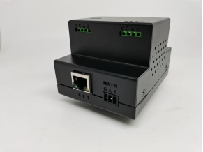
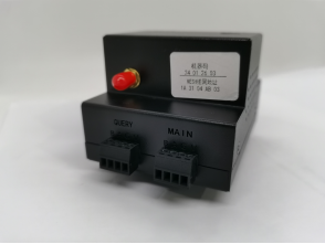
- The interfaces from left to right are NET1 and network interface, respectively, used for network communication of the host;
- Two fast interfaces VGAB, used for bus communication or for supplying power to the host through fast wiring; Behind
- is ANT, and the antenna interface is zgbmesh antenna interface;
- The bottom is a standard DN35 mount.
2. Download materials, install software (solution for missing controls), connect to the host (search for software)
- xxx
Network connection
If you are a LAN user
- , make sure your computer and host are on the same LAN.
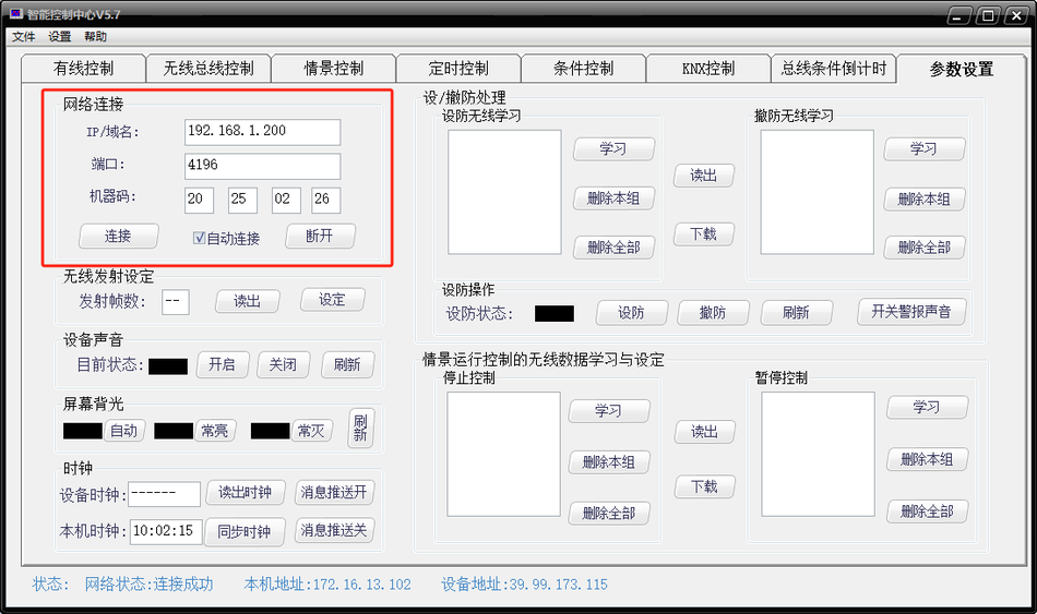
- Under the same local area network, use the network module modifier to search for IP addresses. The initial state of the module is to automatically obtain IP addresses. This software is only used to search, modify, and obtain IP addresses, and the device restarts. On the parameter configuration page, fill in your IP and port in the network connection box to establish a connection with the host through the local area network.
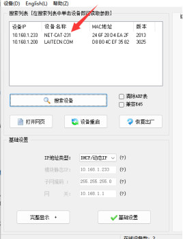
- On the parameter configuration page, fill in your IP and port in the network connection box to establish a connection with the host through the local area network.
If you are a cloud user
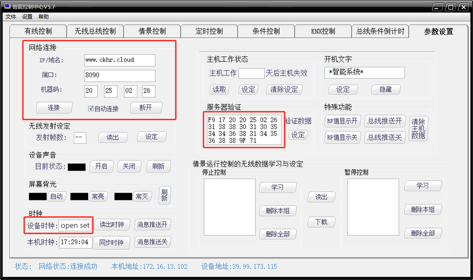
- Just make sure the smart host and your computer are connected to the Internet. On the parameter configuration page, fill in the cloud address and port in the network connection box, and enter the server verification code in the hidden menu of
- On the parameter configuration page, fill in the cloud address and port in the network connection boxopen setto establish a connection with the smart host.
IP/Domain Name:www.ckhr.cloud
Port:8090
Machine Code:(Fill in according to actual situation)
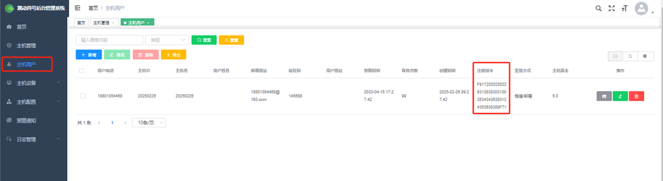
Server Verification:Fill inHost UserRegistration InstructionRegistration instruction(obtained after logging in towww.ckhr.cloud)
(e.g. F9172022502263138383031303534343831343538389F71)
4. Wireless bus button controls Q06 switch
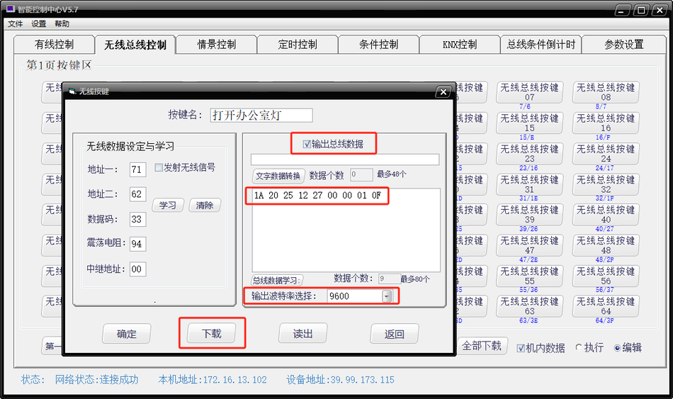
- We will demonstrate how to control Q06, select edit, click the wireless bus button, select output bus data, fill in the opening and closing protocol of Q06 first channel, click download to host, and the status bar at the bottom of the software will prompt successful.
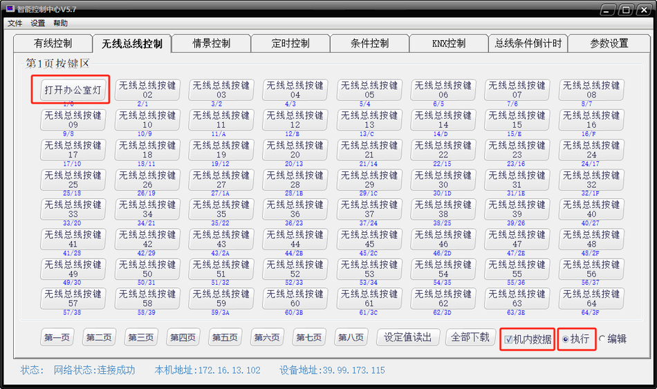
- Check the in machine data and execution, click the button you just edited, and the first path of Q06 will be controlled.
5. Timing Control, Adding Timing Time, Time Proofreading Explanation
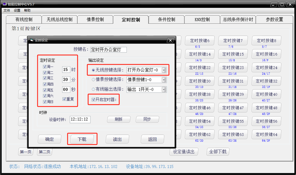
- Timing control supports selecting a time and automatically executing a certain operation when the time is reached. It supports loop and weekly timing, and can switch the timer through other methods.
- Let's demonstrate how to timed open the first relay of Q06, select the time, choose the action to be executed, download it to the host, and when the time is up, the command will be executed.
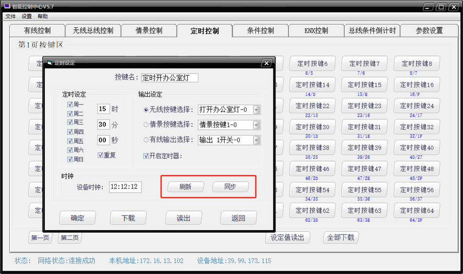
- Click Refresh to obtain the internal clock data of the host, and click Sync to synchronize the computer's time to the intelligent control center.
6. Scenario Control Demonstration
- Scenario control refers to executing multiple instructions at once without the need for independent clicks.
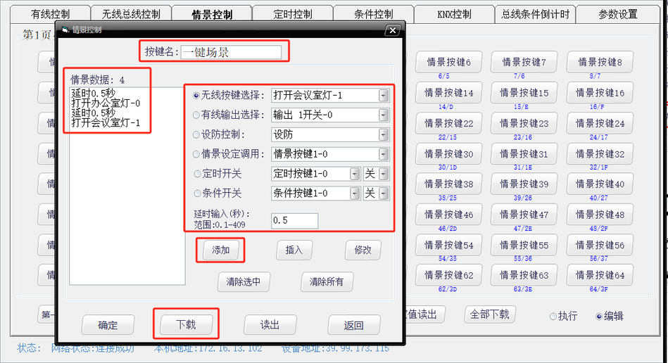
- Open scenario button 1, name one click scenario, default delay of 0.5 seconds, add to turn on office lights, turn on conference room lights, click download.
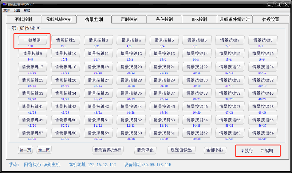
- Clicking on the scenario test intelligent control center will sequentially execute the instructions just added.
7. Bus condition countdown demonstration
- Bus condition countdown refers to triggering any function of the host by receiving custom bus data. The execution time after triggering supports countdown configuration, and the bus countdown condition supports protocol switches.
- Next, we will demonstrate driving a countdown scene through an RS485 switch. Turn on the RS485 switch button 4 to configure custom bus data 11 12 13 14 15
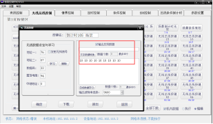
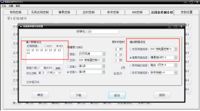
- and drive for 10 seconds before executing the countdown scene.
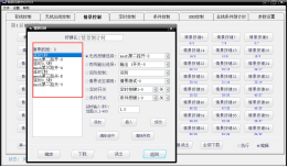
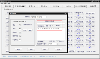
- We have configured the driver host button command on button 2 of the MESH switch, and the countdown condition enable command is configured inside the button. The host button command is configured on button 2, and the countdown condition disable command is configured inside the button. When we press the switch button 5 to turn it on, the scene we set for the driver will be executed after 10 seconds. When we press the switch button 2 to turn off, the conditional countdown will be turned off, and then press the switch button 5 to turn it on. The host will not execute the countdown scene set earlier.
- When we press the switch button 5 to turn it on, the scene we set for the driver will be executed after 10 seconds.
- When we press the switch button 2 to turn off, the conditional countdown will be turned off. Press the switch button 5 again to turn on, and the host will not execute the countdown scene set earlier.
- In the bus condition countdown, we can ignore the checksum byte when the received protocol has checksum or dynamic changes. We only need to keep the fixed part unchanged to drive any function of the host.
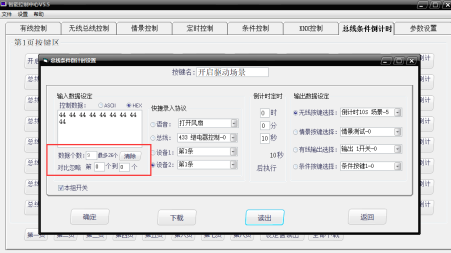
- Bus condition countdown can be driven by MESH or bus.
- We have configured the same functions as the MESH panel using the bus panel. Now we click button 1 to turn it on, and the 10 second countdown scene will start.
- The host can write the relevant protocol of conditional countdown through wireless bus buttons, switch the conditional countdown, and also drive the conditional countdown.
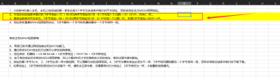
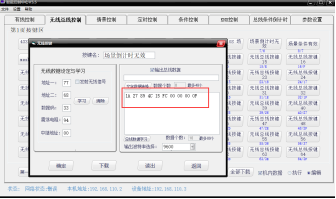
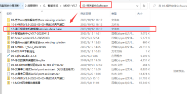
- We will upload the entire demonstration configuration file to a public drive for everyone to download and learn our specific internal logic settings.
8. Parameter Setting Page Explanation
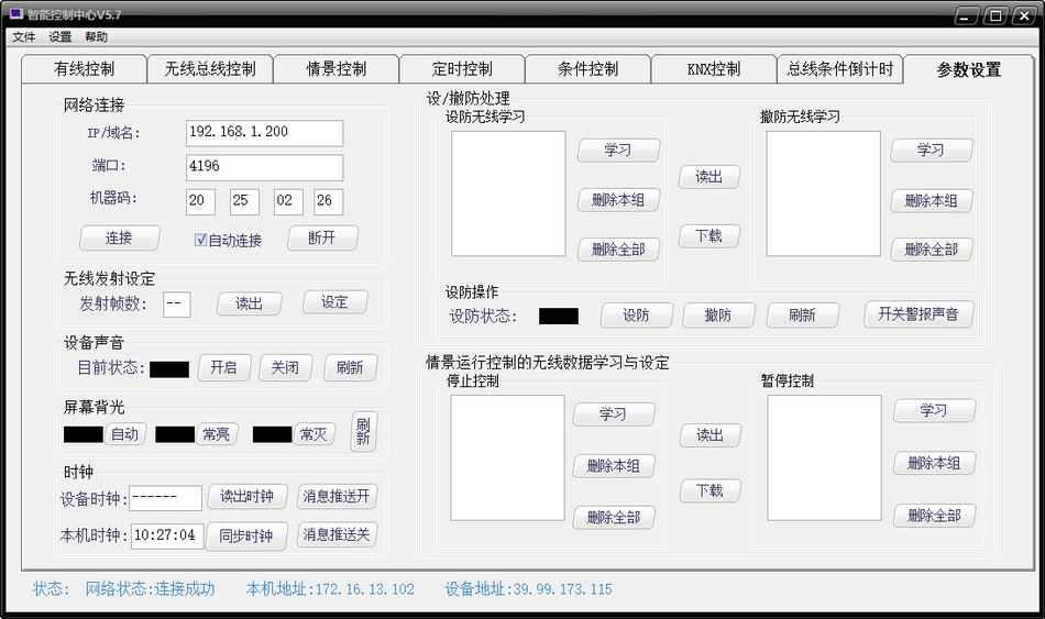
- Network connection refers to the host network address information, IP, and port.
- Device sound switch refers to the prompt sound for operating the host.
- Wireless transmission frame, defense and disarming alarm sound, scene pause and stop, are 1527 wireless functions that M001 does not need to handle. This function can be achieved by triggering the bus condition countdown function through mesh data.
9. Host Connection Cloud Configuration
- Ensure that your computer and host are on the same local area network.
- Open the host network configuration software. exe, click on device management, automatically search, and the host's network information will appear. Under the same local area network, use the network module modifier to search for the IP address. The initial state of the module is to automatically obtain the IP address, and the software is only used to search, modify, and obtain the IP address.
- Use IP: 88 to access the web page for module configuration and settings, such as 10.168.1.233:88. The default username and password are admin and admin.
- Enter port one, which contains two network port numbers that can be configured to connect to two servers. We use 4196 to connect to a private cloud here. Select TCP client as the working mode.
- Destination IP and domain name, fill in the IP or domain name of the private cloud.
- Fill in the registration package selection link and send a custom data package, such as F9171020122128EDD442758CCA3C9C9F71.
- Fill in the heartbeat packet and select a heartbeat time of 60 seconds, with data such as 8A 00 00 01 (check hexadecimal).
- Click OK to confirm successful configuration, restart the module to link to the private cloud.
10. Basic explanation of APP usage
- Scan the QR code to add a host, as it automatically obtains the IP address, you need to edit the host and fill in the correct IP address and port.
- Button name synchronization, click on the menu in the upper left corner, click synchronization, and the button names edited by the intelligent control center will be synchronized to the phone.
- Synchronization principle: Automatically retrieve the name set on the PC to reduce manual input. For example, when Wireless 1 corresponds to the on state of the living room light, the name of the on state of the living room light is synchronized. When adding, select the host resource to add according to the living room light on. Before synchronization, all data needs to be downloaded from the intelligent control center, including wired, wireless bus, scenario, timing, etc.
- When adding, select the host resource to add according to the living room light on.
- Before synchronization, all data needs to be downloaded from the intelligent control center: wired, wireless bus, scenario, timing, etc.
- Host resource addition, create a new room named host button, click on add device, select host resources, search for mesh in all places, and the synchronized button will be filtered out. You can also choose the category below to add. After selecting the output settings, choose an icon and click save to complete the addition of host resources.
- After selecting the output settings, choose an icon and click save to complete the addition of host resources.
- Q04 addition, the four buttons of Q04 can be easily added to the APP by scanning the relay QR code on the Q04 body.
- After scanning and adding, we can control the four buttons of Q04 with our mobile phone and provide real-time feedback on the status. The dropdown interface can refresh the status.
- To use the timer function, click on the menu to schedule tasks.
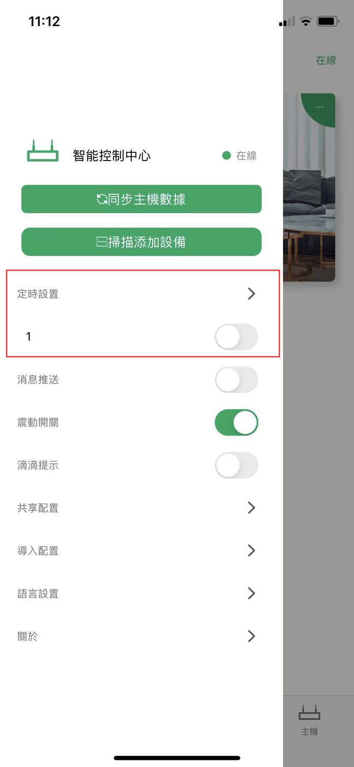
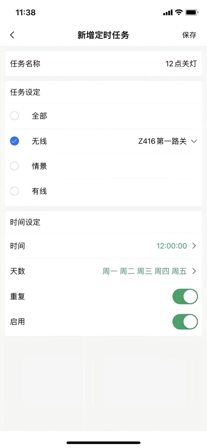
- Common methods and table locations for generating QR codes for devices can be found in the fourth file of the protocol document folder, 04- Device QR Code Generation Table. Simply follow the method in the table to generate the QR code and add the device. For other usage methods of the APP, please refer to the detailed introduction of the APP's baby interface.
- For other usage methods of the APP, please refer to the detailed introduction of the APP's baby interface.
Professional User Tutorial
1. Using the serial port assistant, control the host function by sending a protocol through the USB to 485 module
- Install the serial port debugging assistant, unzip and click to run.
- Install USB to 485 driver.
- Select HEX for receiving settings and HEX for sending settings.
- Select the corresponding serial port number, baud rate 9600, data bit 8, checksum none, stop bit 1, flow control none, and click start.
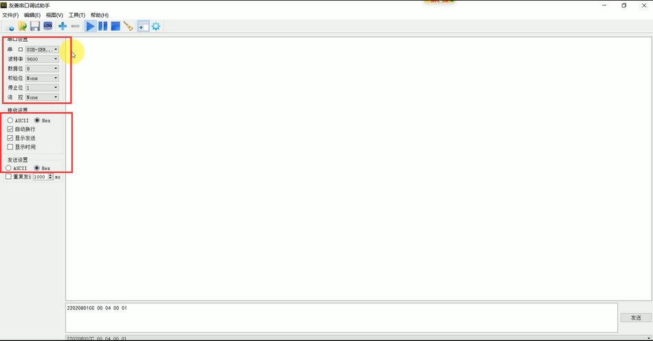
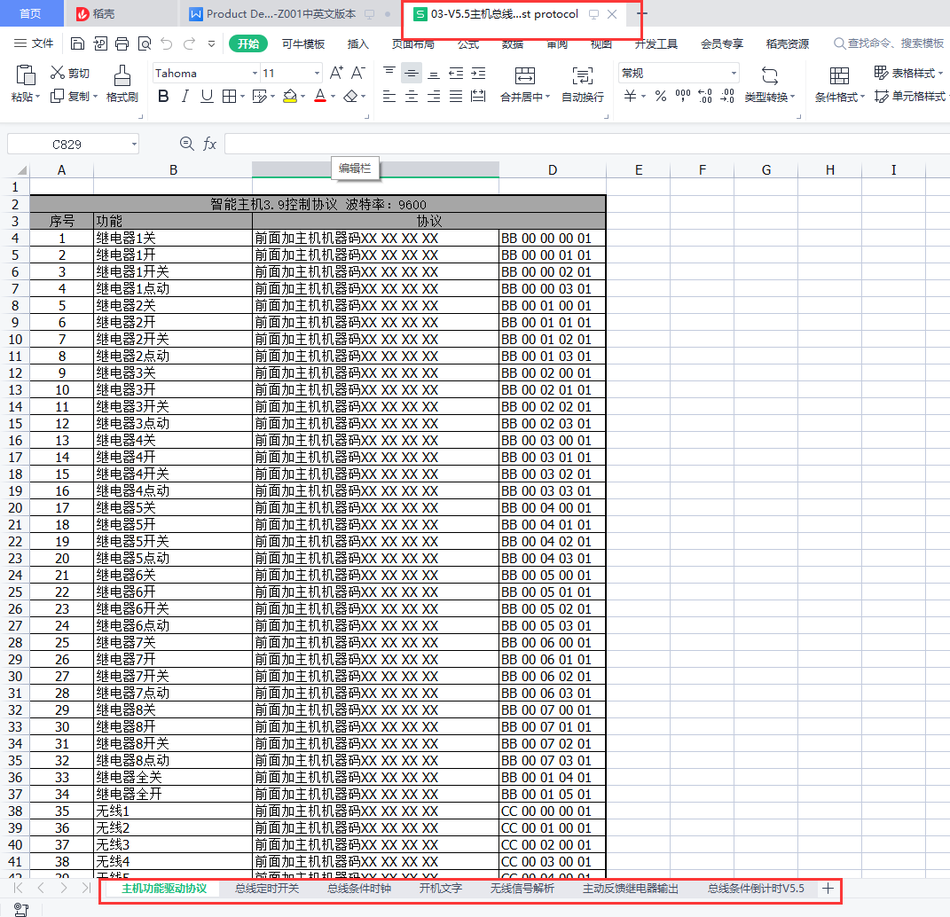
- Open the protocol table of the intelligent control center. Copy the protocol of the corresponding button on the host to the data sending box, click send, and the corresponding button will be controlled.
- Copy the protocol of the corresponding button on the host to the data sending box, click send, and the corresponding button will be controlled.
- Copy the corresponding control protocol to control other functions of the host.
2. Use serial port assistant to control host functions through network protocol transmission
- Install serial port debugging assistant, unzip and click to run.
- Select HEX for receiving settings and HEX for sending settings.
- Select TCP/UDP for the serial port, choose Tcp client for the Mode, enter the host IP for the IP, enter the host port for the port, and click Start. If you don't know the IP and port of the host, please watch Basic Knowledge Video 2.
- If you don't know the IP and port of the host, please watch Basic Knowledge Video 2.
- Open the protocol table of the intelligent control center. Copy the protocol of the corresponding button on the host to the data sending box, click send, and the corresponding button will be controlled. Copy the corresponding control protocol for other functions of the control host.
- Copy the protocol of the corresponding button on the host to the data sending box, click send, and the corresponding button will be controlled.
- Copy the corresponding control protocol to control other functions of the host.
3. Explanation of Transparent Transmission Function between Host Network Bus MESH
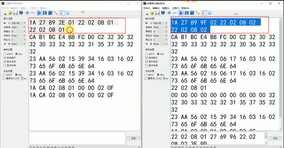
- Network Transparent Transmission Bus. In the serial port debugging assistant box: Add machine code+CD B8 B4 AB+custom data before the data you need to transmit transparently. Click send custom data to be transmitted transparently to the bus network.
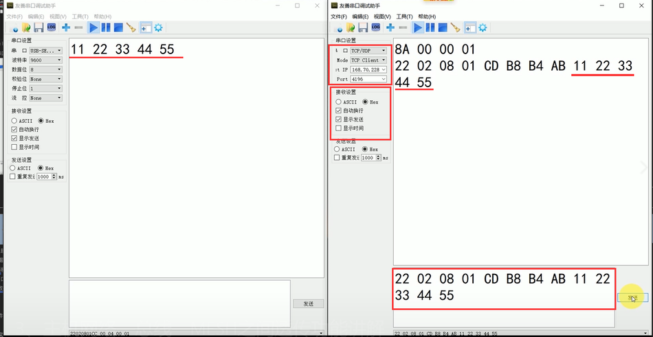
- Bus transparent transmission network, any data packet on the bus with less than 80 bytes will be automatically transmitted through the host to the network client.

- Open two serial assistants A and B. Serial assistant A connects to the host through the network, while serial assistant B uses USB to 485 to connect to the host's 485 interface. Send data 11 22 33 44 through serial assistant B, and you will receive 11 22 33 44 on the network port.
- MESH to network and 485, as long as the MESH devices with the same networking parameters send data through MESH, the data bus and network will receive the customized data.
- Open another serial assistant C, connect the MESH to 485 module through USB to 485, and send data through the serial assistant 11 22 33 44. Both serial assistants A and B will receive corresponding transparent data.
4. PC configuration file office modification
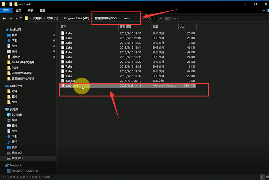
- In order to facilitate quick modification of PC configuration files, we have used the most commonly used OFFICE database, which can be exported to EXCEL for quick batch data editing and modification. Next, taking the modification of wireless bus button data as an example, find the data_stave database file in the back folder of the installation directory and open it with OFFICE ACESS.
- Next, let's take modifying wireless bus button data as an example. Find the data_stave database file in the back folder of the installation directory and open it with OFFICE ACESS.
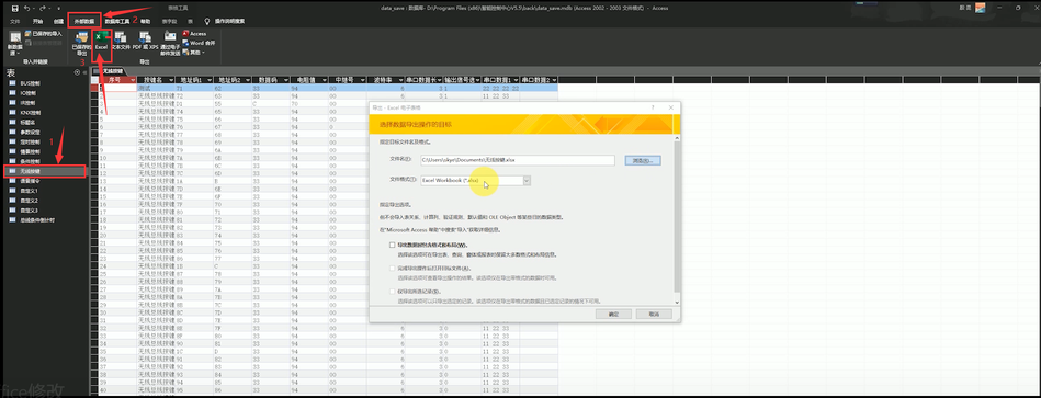
- Click to enable content, double-click the wireless button to see the data content of the wireless button, click on external data, export to Excel, select default options, click confirm, be careful not to modify the name of Excel.
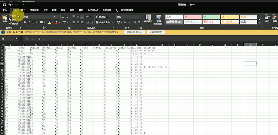
- Next, you can modify and open Excel according to your own needs to modify the content. If you don't know the meaning of the content, you can add data on the buttons to obtain data patterns. After editing the data you need, click save.
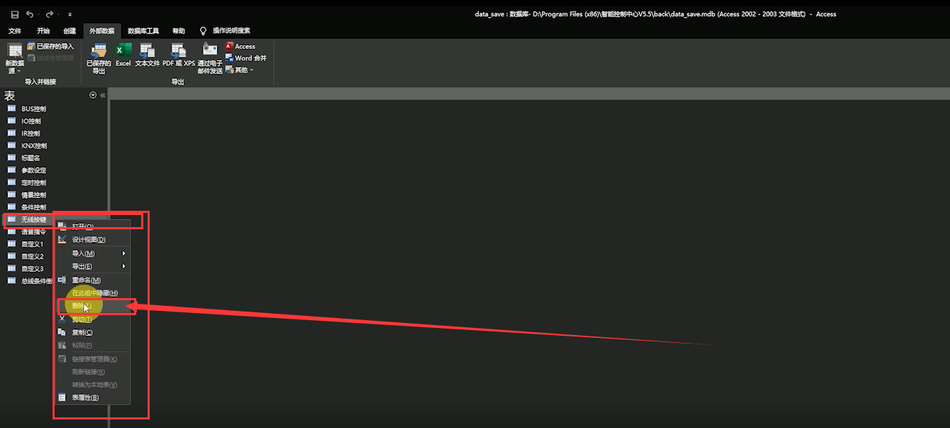
- Then we will import the Excel data into the database. Firstly, delete the table of wireless keys in the database, then select external data, new data source, from the file, Excel.

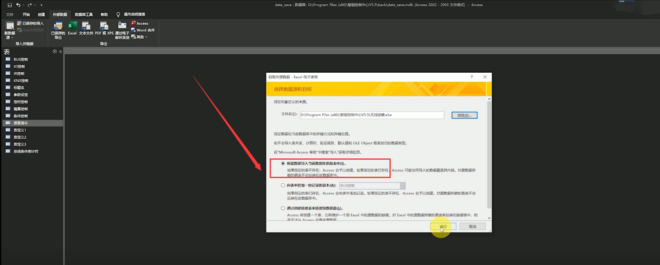
- Browse and select Excel, choose to import the source data into a new table in the current database, and click OK.
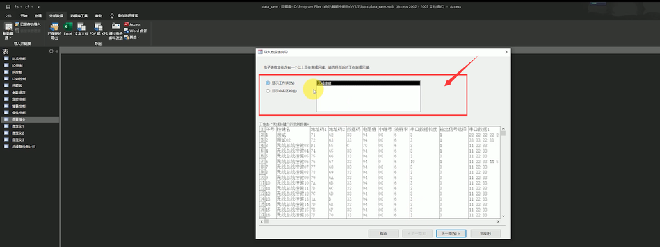
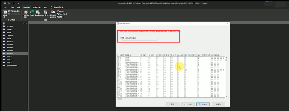
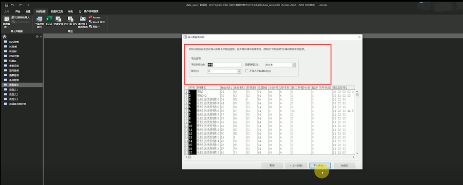
- Select Display worksheet, click Next, select the first row containing column headings, click Next, select default field information, then click Next, select Do not have primary key, click Next, import to the list name as EXCEL file name, and click Finish.

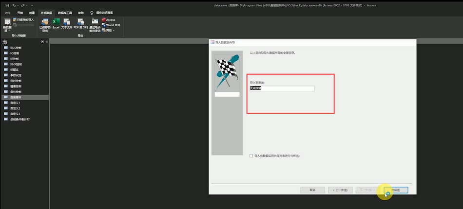
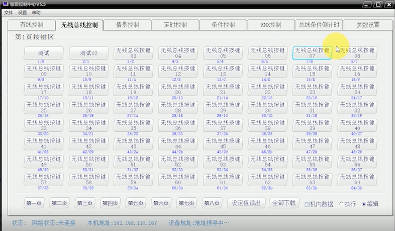
- Open the PC program again and you will find that the internal data of the buttons has been changed to the content you entered into EXCEL.
5. APP, SQLite app database modification
- The database of the APP can be opened and modified through SQLite.
- The SQLite software is located in the 6th file of the relevant software folder, 06- sqlitestudio -2.1.4.
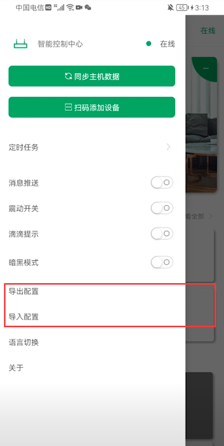
- Refer to the APP software video on how to export the APP configuration file. Export the file, click on the SQLite application, and open the database file.
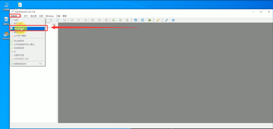
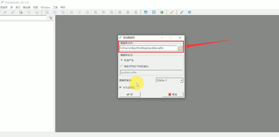
- Select the table you want to modify, double-click the table, and then click on the data label at the top of the table to modify the content in the database.
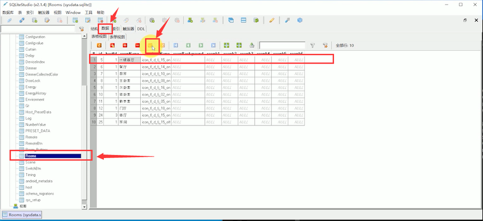
- After clicking save, import the configuration file into your phone.
- Reopening the app will result in the updated configuration.
6. Explanation of host cluster control, using one host to control multiple hosts
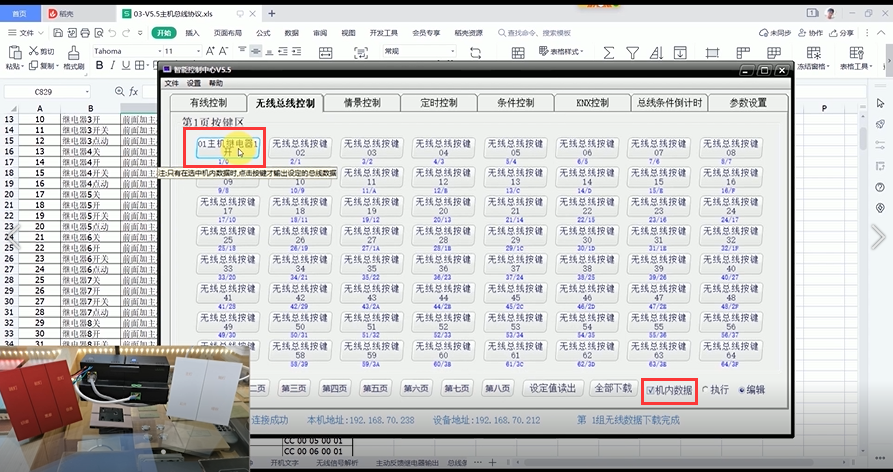
- By configuring the MESH networking parameters of the host to be the same, mutual calling and communication between hosts can be achieved.
- Configure the MESH networking parameters of host AB to be the same, open the host protocol document, write the control protocol of host B in the wireless bus button of host A, and click download.

- Check the data in the machine, select 'Execute', click the button just edited, and host A will control host B.
7. Display of location for secondary development materials search and sample source code folder location
- The secondary development materials are located in folder 04 of the cloud storage host directory.
- The 01 and 02 documents are communication documents between the host PC and the host.
- The 03 document is the source code for connecting intelligent control centers through SOCKET on various platforms.
8. Modify the host MESH networking parameters
- Connect the 4196 port of the host through the network using the serial port assistant.
- By modifying the MESH address, the networking parameters can be adjusted.
- Address modification machine code+CD B8 B4 AB+5 bytes original address+F8 E7 D6+5 bytes new address.
- Due to the fact that changing the address will modify the MESH networking parameters, it will take about 4 seconds for feedback on the modified address. Please do not turn off the power during the modification process.
- The first byte of the address is 1A, and the second and third bytes must be the same to form a network, which can be understood as your network password. The module addresses of 4 and 5 bytes must be different, and the 5 bytes must be consistent with the last byte of the machine code, otherwise it will cause the bus condition countdown to fail to download.
- If the address 2 and 3 bytes are modified differently from other MESH devices, communication will be immediately interrupted. You need to modify the MESH address 2 and 3 bytes to be the same in order to re network communication.
Frequently Asked Questions Tutorial
1. Method for determining whether the communication function of the host bus is normal
- Unplug the 485 interface device from the host and switch to a standalone host.
- Connect the 4196 port of the host through the network using the serial port assistant and send the protocolMachine code+CD B8 B4 AB BB BB BB BB BB 86 86 0FReturning a 5-byte MESH address+64 bytes of data (regardless of data content)+0F indicates that the host is functioning properly.
2. Common bus fault handling and troubleshooting methods, host device circuit
- Bus faults are mainly investigated from control devices, controlled devices, and circuits.
- Control device host troubleshooting: Unplug the 485 interface device from the host and switch to a standalone host. Connect the 4196 port of the host through the network using the serial port assistant and send the protocolMachine code+CD B8 B4 AB BB BB BB BB BB 86 86 0FReturning a 5-byte MESH address+64 bytes of data (regardless of data content)+0F indicates that the host is functioning properly.
- Troubleshooting of controlled equipment: If the controlled equipment is directly connected to the host through a separate bus and the control is normal, it indicates that there is no problem with the controlled equipment. If it is not normal, there is a problem with the equipment.
- Line investigation: Next, we will investigate the line problems. Due to the different wiring of each student, we need to provide a line sketch so that we can provide a specific investigation plan.
3. Explanation of several situations of host prompt sound
- The prompt sound is an important auxiliary reminder tool that helps everyone understand the system's operating status. Under what circumstances will a prompt sound be emitted when the host is turned on?
- There is data transmission on the bus.
- Use software to operate the host, download, read, control, etc.
- There are devices on the bus that keep sending data.
- There is interference on the bus.
- As we all know, bus faults are mainly investigated from three aspects: control equipment, controlled equipment, and circuits. The first two are easy to troubleshoot, but line faults are difficult to find.
- Generally, the AB bus device has two wires, and regardless of whether you have wired it incorrectly or not, it will not give you any prompts. Only when you experience uncontrollable symptoms will you come to find the cause in the device circuit.
- The intelligent control center has a unique design that can detect interference in the circuit. When there is interference in the circuit or when there is a large amount of messy data, it will emit beeping alarm sounds to assist in troubleshooting.
- The prompt sounds A and B are normal operating conditions that do not need to be handled.
- The situation of prompt sound C
- All devices in the store include third-party integration and are controllable in sending data to the bus, without actively sending data.
- If you join a third-party device to send a large amount of data on your own, you need to contact the third-party device manufacturer to investigate the cause, or use an isolation module to isolate it from sending data to the bus, occupying the bus network.
- The situation of prompt sound D
- The general troubleshooting method for bus faults can be used.
Packaging List
- Intelligent Control Host M002
- Antenna
- Manual
- Warranty Card
- Certificate of Conformity


Leave a Reply